

Page 1
Document 483971
Models SP-AP0511W and SP-AP0511WL
®
Ceiling Exhaust Fans
Installation, Operation and Maintenance Manual
Please read and save these instructions for future reference. Read carefully before attempting to assemble, install,
operate or maintain the product described. Protect yourself and others by observing all safety information. Failure
to comply with these instructions will result in voiding of the product warranty and may result in personal injury
and/or property damage.
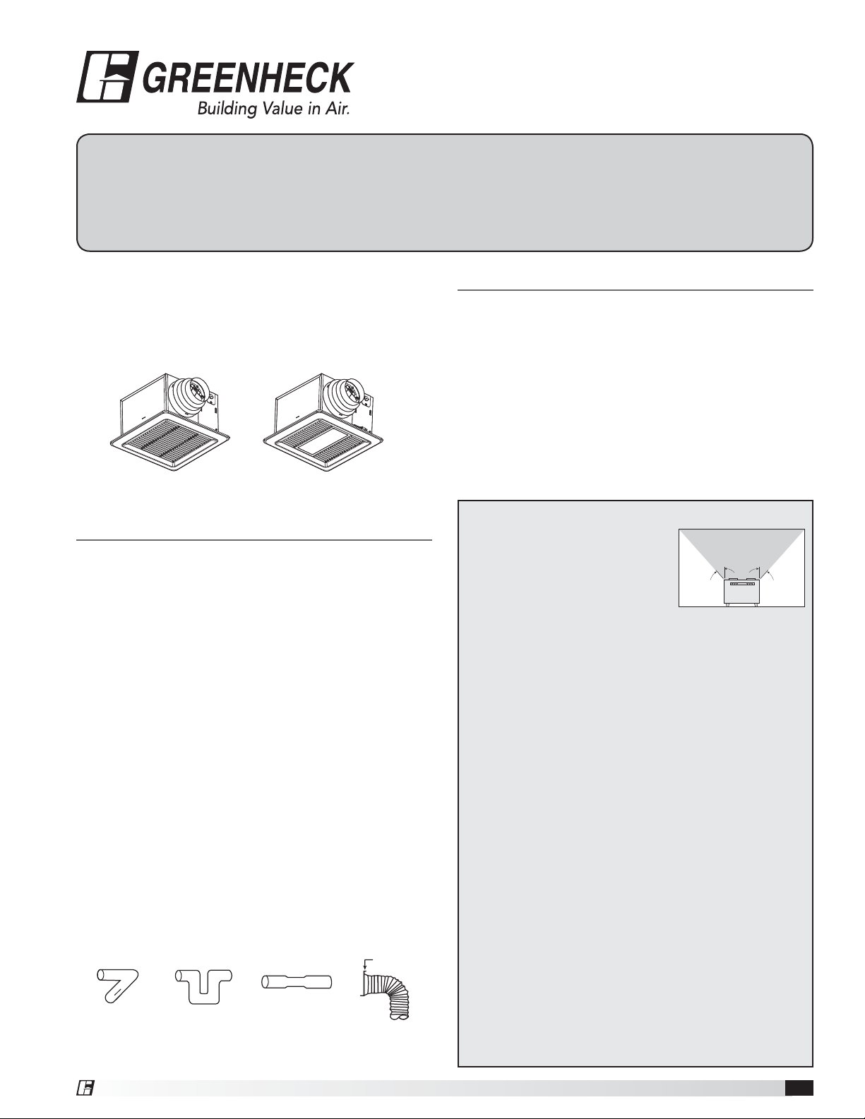
Ceiling Exhaust Fan
Designed for clean air applications where low sound
levels are required. Many options and accessories are
available such as lights, motion detectors, humidity
sensors, CO
sensors, and night lights.
2
SP-AP0511W SP-AP0511WL
General Safety Information
Only qualified personnel should install this fan.
Personnel should have a clear understanding of these
instructions and should be aware of general safety
precautions. Improper installation can result in electric
shock, possible injury due to coming in contact with
moving parts, as well as other potential hazards.
1. Do not install this ventilation fan where interior room
temperature may exceed 104°F (40°C).
2. Make sure that the electric service supply voltage is
AC 120V, 60Hz.
3. Follow all local electrical and safety codes, as well as
the National Electrical Code (NEC) and the National
Fire Protection Agency (NFPA), where applicable.
Follow the Canadian Electric Code (CEC) in Canada.
4. Always disconnect the power source before working
on or near the fan, motor, light fixture, or junction
box.
5. Protect the power cord from sharp edges, oil,
grease, hot surfaces, chemicals or other objects.
6 Do not kink the power cord.
7. Do not install the unit where ducts are configured as
shown in Fig. 2.
8. Provide make up air for properventilation.
Fig. 2
Adaptor
Table of Contents
Supplied Accessories ...................... 2
Dimensional Data ......................... 2
Wiring Diagrams .......................... 3
Features ................................. 3
Plug and Play Accessories .................. 4
Installation for New Construction ............. 5
Retrofit Installation ......................... 9
Maintenance ............................. 10
Typical Installation ........................ 11
Our Commitment ...................Backcover
CAUTION!
• For general ventilating use only. Do
not use to exhaust hazardous or
explosive materials and vapors.
• Not for use in cooking areas (Fig. 1)
• This product must be properly
grounded.
WARNING!
To reduce the risk of fire, electric shock, or injury to persons,
observe the following:
• Use this unit only in the manner intended by the manufacturer. If
you have questions, contact the manufacturer.
• Before servicing or cleaning unit, switch power off at service panel
and lock service disconnecting means to prevent power from
being switched on accidentally. When the service disconnecting
means cannot be locked, securely fasten a prominent warning
device, such as a tag, to the service panel.
• Installation work and electrical wiring must be done by qualified
person(s) in accordance with all applicable codes and standards,
including fire-rated construction codes and standards.
• Sufficient air is needed for proper combustion and exhausting
of gases through the flue (chimney) of fuel burning equipment
to prevent back drafting. Follow the heating equipment
manufacturer’s guideline and safety standards such as those
published by the National Fire Protection Association (NFPA),
and the American Society for Heating, Refrigeration and Air
Conditioning Engineers (ASHRAE) and the local code authorities.
• When cutting or drilling into a wall or ceiling, do not damage
electrical wiring or other hidden utilities.
• Ducted fans must always be vented to the outdoors.
• Do not use this fan with any solid state speed control.
• If this unit is to be installed over a tub or shower, it must be
marked as appropriate for the application and be connected to a
Ground Fault Circuit Interrupter (GFCI) protected branch circuit.
• These models are ETL listed for tub and shower enclosures.
• These fans are not to be installed in a ceiling thermally insulated
to a value greater than R40.
Fig. 1
Do not install
fan in this area
45° 45°
®
Ceiling Exhaust Fans 1
Page 2
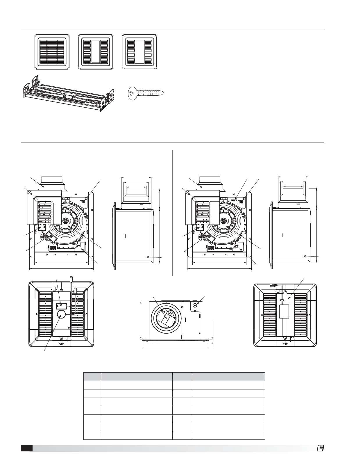
Supplied Accessories
Standard
or
Lighted Motion and/or
or
Grille (Qty. 1)
Suspension Bracket
Assembly (Qty. 1)
Dimensional Data
SP-AP0511W (shown with optional
sensorinsert)
3
2
7
Night Light
Screw (ST4X30)
(Qty. 5)
5 3/4 (147)
4 7/8 (123)
3 7/8 (98)
3 3/4 (97)10 3/8 (265)
SP-AP0511WL (shown with light)
3
2
14
7
5 3/4 (147)
4 7/8 (123)
3 7/8 (98)
3 3/4 (97)10 3/8 (265)
9
10
10 1/4 (260)
12 1/8 (308)
12
11
Unit dimensions are inches (mm)
No. Description No. Description
1 Wheel 8 Control box
2 Grille 9 Humidity sensor module
3 Duct adaptor 10 CO
4 Damper 11 Night light module
5 Housing 12 Motion sensor module
6 Knockout plate 13 LED light (includes night light)
7 Junction box 14 LED light receptacle
9
1
8
4
7 3/8 (186)
10
5
13 (330)
10 1/4 (260)
12 1/8 (308)
6
5/8 (14.5)
sensor module
2
1
5
8
13
Ceiling Exhaust Fans2
®
Page 3
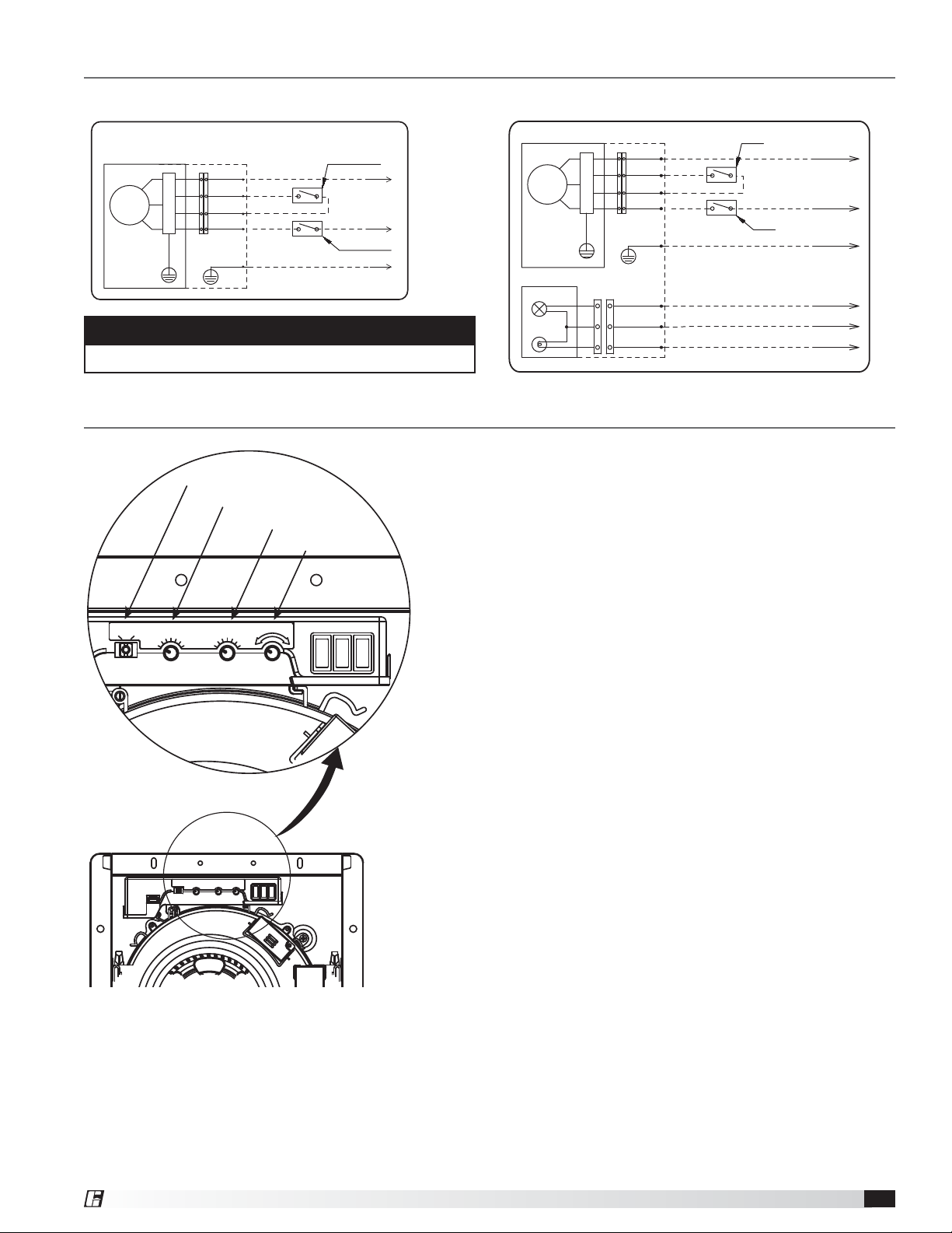
Wiring Diagrams
Fan only model
Fan body
Motor
Yellowgreen
Junction box
P
C
B
White
Red
Red
Black
Green
Neutral
Signal
Signal
Live
Earth ground
CAUTION
Do not apply 115V to red wires.
Features
Flow Selection
Multi-Speed
Time Delay
50 80 110
Air Volume(CFM)
50
40
30
0
Time(min)
60
70
90
Air Trimming
30
20
L
10
45
5
60
0
Control switch
Power switch
Air Trimming
H
With light model
Fan body Junction box
Neutral
White
Motor
Yellowgreen
Light Body
P
C
B
Brown
White
Blue
Red
Red
Black
Green
Signal
Signal
Live
Earth ground
Live (Light)
Neutral
Live(N. Light)
All fans are supplied with flow selection switch, multi-speed
dial, time delay dial and air trimming dial.
• Flow Selection: The switch chooses 50, 80 or 110 cfm and
is the default highspeed.
• Multi-Speed: The switch allows the fan to run continuously
at low speed.
Example: Flow Selection setting is 110 cfm, Multi-Speed
can be chosen 0, 30, 40, 50, 60, 70 or 90 cfm as a
lowspeed
• Time Delay: This sets the time required to return to low
speed after high speed input is completed. Setting range is
0, 5, 10, 20, 30, 45 or 60 minutes.
• Air Trimming: Allows for adjustment of the airflow up to
70cfm. Dial adjustments impact high and low speed.
Control switch
Power switch
®
Ceiling Exhaust Fans 3
Page 4
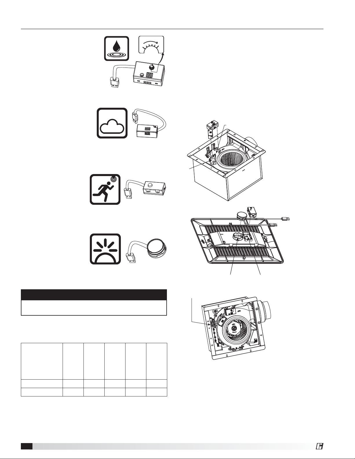
Plug and Play Accessories
Humidity Sensor: The fan
runs at or boosts to high
Humidity(RH%)
80
30
speed when humidity value
exceeds user selected set
point. The fan returns to
low speed after a period
of time delay or when
humidity value is lower
than set point. Humidity
detection value setting range: 30%-80%.
CO
Sensor: The
2
module begins to detect
environmental CO2
CO
concentration when
2
fan has been on for 2
minutes. The fan runs at or boosts to high speed when
concentration level is over 1000 ppm. The fan returns
to low speed after a period of time delay or when
concentration level is less than 800 ppm.
Motion Sensor: The fan
runs or boosts to high
speed when motion
sensor is activated. The
fan returns to low speed
after a period of time delay or when you are out of
detection range. The range is limited to 10 ft. height and
a 90° field of view.
Night Light: Night Light
module automatically
turns on according
to environmental
brightness. The night
light automatically turns
on when the environment is dark, and turns off when the
environment is well lit.
Installation of plug and play accessories
You can purchase the specified devices described.
Install into the corresponding position:
Position A is for CO
Position B is for Humidity Sensor
Position C is for Night Light
Position D is for Motion Sensor
Attach the specified devices to the slot, until you hear
the device click into place.
Access USB interface, insert the connector of the
accessory into USB receptacle.
A
Sensor
2
B
C
D
NOTE
All accessories are sold separately and are not
included in base fan model.
A maximum of three accessories can be used. Optional
accessories and model compatibility are listed as
follows.
Model
SP-AP0511W XXXX
SP-AP0511WL X X Included X
Ceiling Exhaust Fans4
Sensor
2
CO
Sensor
Humidity
Motion
Sensor
Night Light
LED Light
USB Receptacle
®
Page 5
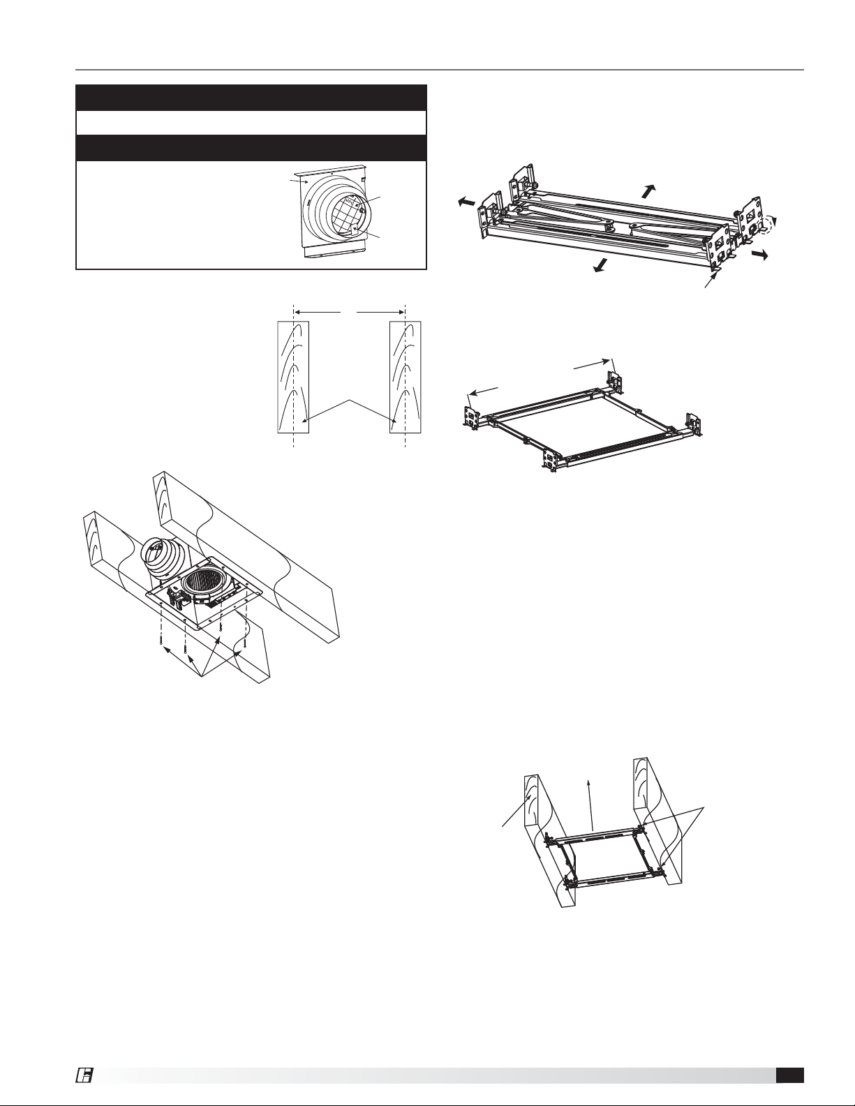
Installation for New Construction
CAUTION
Please wear gloves during the installation process.
IMPORTANT
Adaptor
Remove the tape from
the damper and adaptor
before installation.
Joist Information
• 12 inches (305 mm)
If the spacing of L is 12 inches
(305 mm) on center, follow the
installation as shown in Fig. 1.
Secure four screws (ST4X30)
at flange of frame to the joists.
Then follow steps 6 through 9
on (pages 6 through 7) to
complete the installation.
L
Joists
• 16 to 24 inches (406 to 610 mm)
If the spacing of L is 16 to 24 inches (406-610 mm),
please use the suspension bracket assembly as shown
in Figures 2a and 2b.
Damper
Tape
Ta b
Fig. 2a: 16 to 24 inch On Center Joists
Suspension Bracket Assembly
11 3/4~22 1/2
(300~579)
Unit: inches (mm)
Fig. 2b: Suspension Bracket Assembly
4 Screws
(ST4x30)
Fig. 1: 12 inch On Center Joists
Suspension Bracket Installation,
Steps 1 through 11
1. Bend down the eight tabs for positioning as shown
in Fig. 2a and unfold the bracket assembly, Fig. 2b.
2. Attach one side of the bracket assembly to the joists
by drilling 2 captured self-tapping screws (ST4X20).
See Fig. 3.
3. Adjust the length of the bracket assembly by pulling
the unsecured end of the bracket assembly towards
the joist. Attach the unsecured side of the bracket
assembly to the joist by drilling the (2) captured, selftapping screws (ST4X20) to the joist. See Fig. 3.
Active Part
Screws
(ST4X20)
Joist
Fig. 3
®
Ceiling Exhaust Fans 5
Page 6
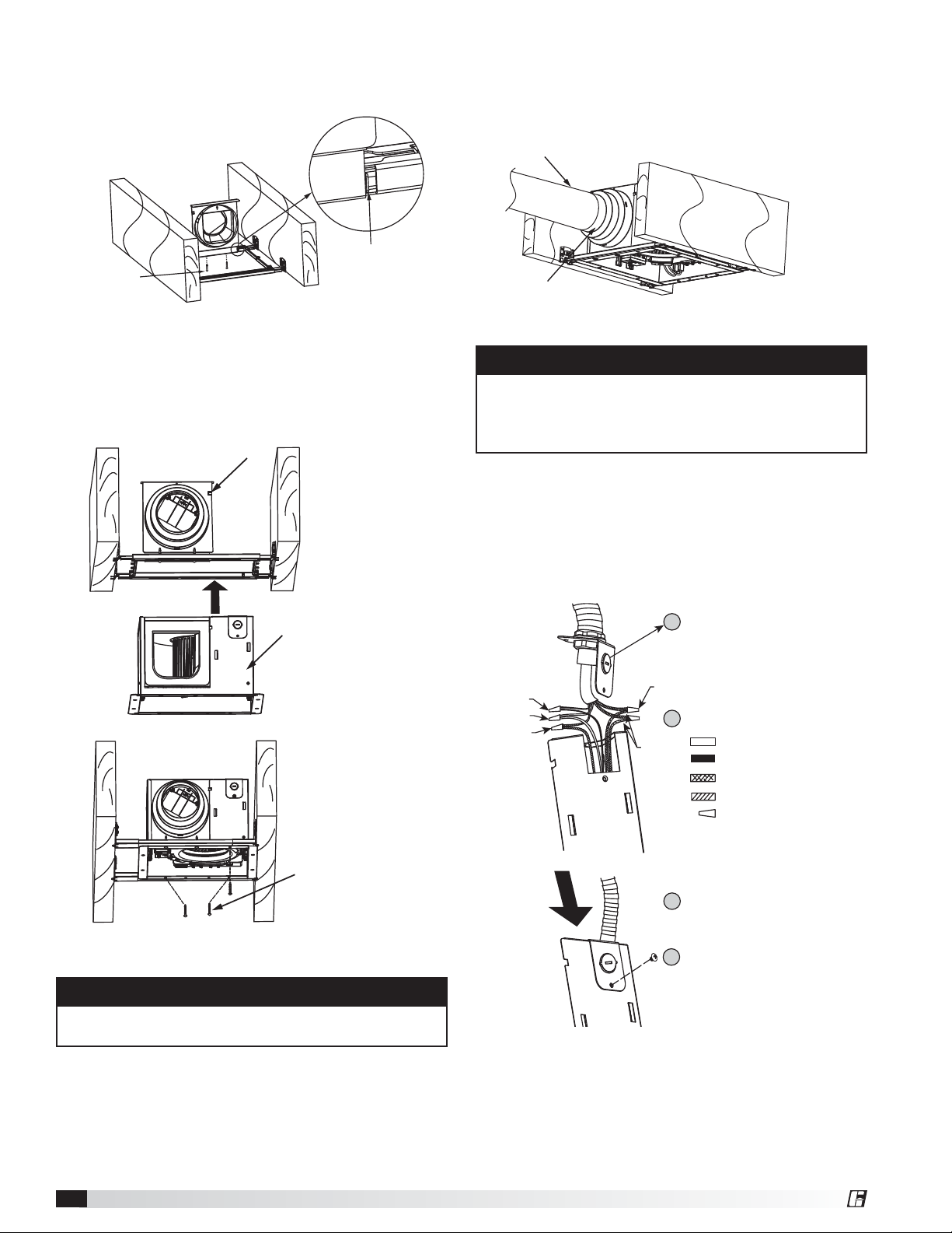
4. Place the adaptor on the bracket assembly as
indicated and install it by using 2 self-tapping screws
(ST4X30). See Fig. 4
6. Install circular duct and secure it with clamps or ties
and seal it with mastic or approved duct tape. Duct
adaptor can accept 4, 5 or 6 inch (101.6, 127 or
152.4 mm) circular duct. See Fig. 6
Circular duct
2 Screws
(ST4X30)
Position
of adaptor
Fig. 4
5. Push the fan body upwards until the fan body
engages the buckle on the adaptor and secure the
fan body by using the other 3 self-tapping screws
(ST4X30). See Fig. 5
Buckle
Fan Body
Duct tape
Fig. 6
IMPORTANT
Follow all local electrical and safety codes, as well as
the National Electrical Code (NEC) and the National
Fire Protection Agency (NFPA), where applicable.
Follow the Canadian Electric Code (CEC) in Canada.
7. Remove the knockout plate and secure conduit or
stress relief to knockout hole. See Fig. 7a.
Refer to wiring diagrams on page 3. Use UL
approved connectors to connect the incoming power
wires to the ventilation fan wires, see Fig. 7b. Then
attach knockout plate to the fan body.
Attach cable clamp to Knockout Plate.
1
Knockout Plate mounts to outside of
Fig. 7a
Black Wires
White Wires
Green Wires
Fig. 7b
housing and may be oriented as desired.
Wire Nuts
Connect wires with UL approved connectors.
2
Red Wires
White
Black
Red
Green
Wire nuts
3 Screws
(ST4x30)
Fig. 5
CAUTION
Hold the fan body to prevent falling before installing
the screws.
Ceiling Exhaust Fans6
Align Knockout Plate to Housing
3
Insert Screw from Parts Bag
4
®
Page 7
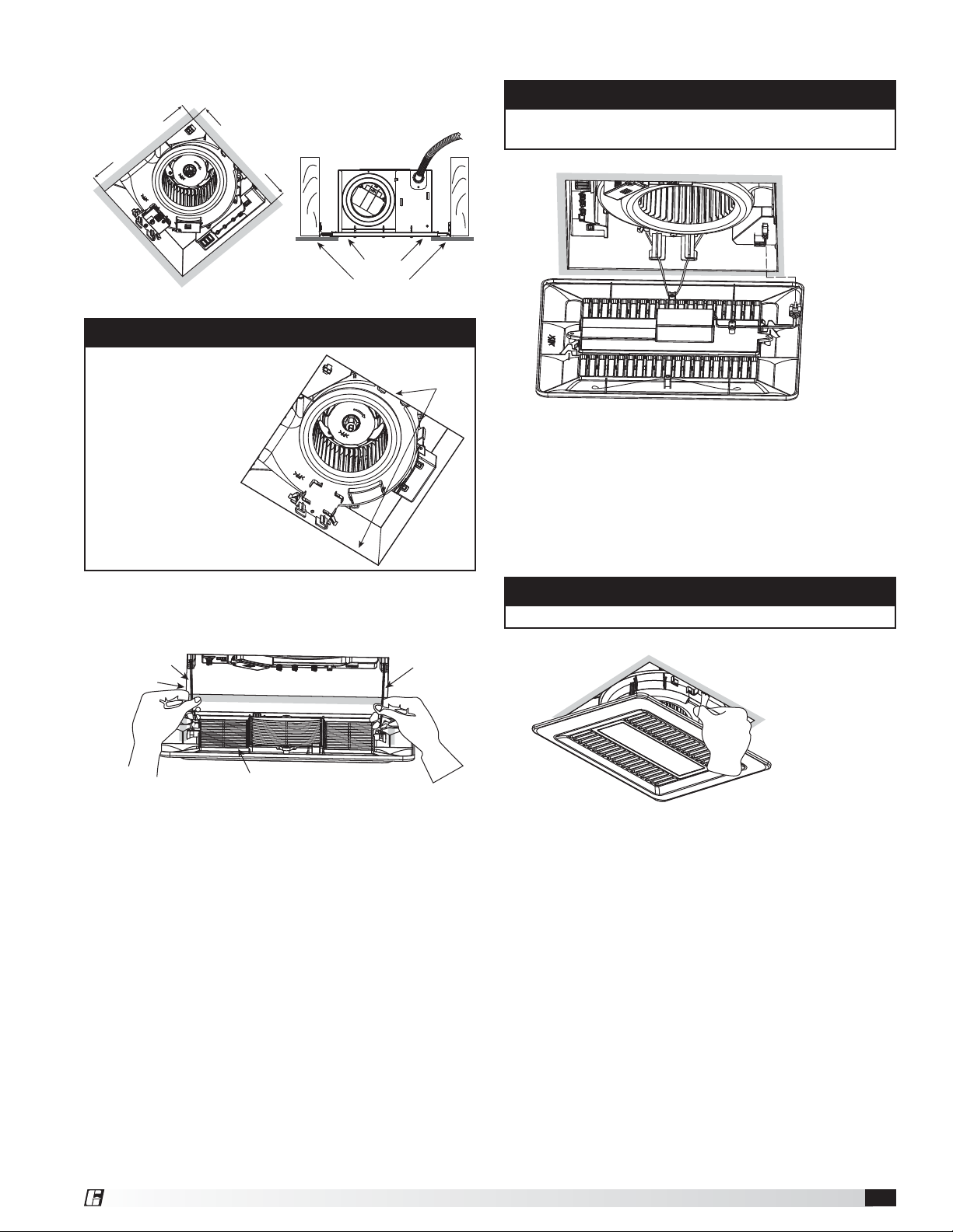
8. Finish ceiling work. Ceiling hole to be aligned with
the inside edges of the flange. See Fig. 8
10-3/8 (265)
10-3/8 (265)
Caulk
Fig. 8
inches (mm)
Ceiling
IMPORTANT
After finishing the ceiling
work, fill gap between
flange and ceiling with
caulk or other sealant
to prevent airleakage.
Caulk
10. For model SP-AP0511WL, with light
CAUTION
• Before turning on the light, make sure the plug is
fully engaged.
Fig. 10
a. Insert the grille mounting spring on the wiring side
into the slot. See Fig. 10
b. Insert the plug into the receptacle in the housing
and insert the other mounting spring into the slot as
shown and mount grille to fan body.
See Fig. 10 and Fig. 11
9. Insert mounting springs into slots and mount grille to
fan body. See Fig. 9
Slot
Ceiling
Grille
Fig. 9
Mounting
Spring
CAUTION
Mount carefully so that light wiring is not pinched.
Fig. 11
®
Ceiling Exhaust Fans 7
Page 8
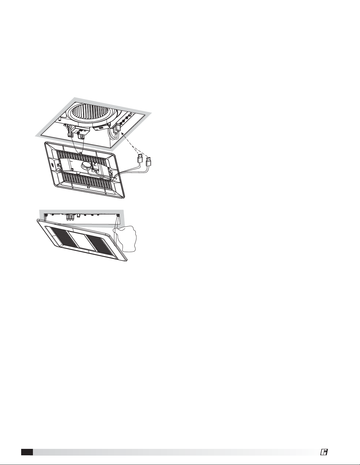
11. For grille with a module, refer to the following
installation method.
a. Insert the grille mounting spring on the wiring
side into the slot.
b. Insert the USB connector into the USB
receptacle (see page 4 for appropriate USB port
configuration) and insert other mounting spring
into the slot as shown and mount grille to fan
body. Avoid pinching module wires. (Fig. 12)
Fig. 12
Ceiling Exhaust Fans8
®
Page 9
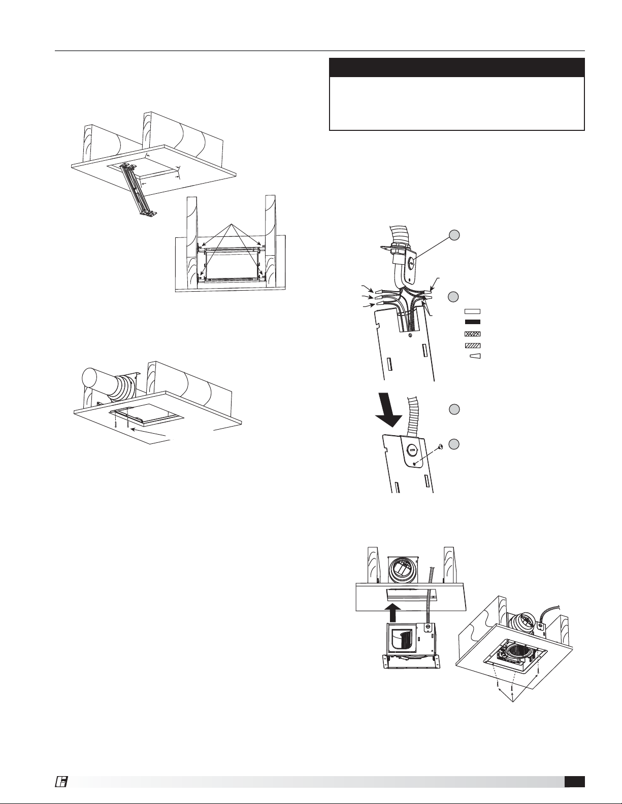
Retrofit Installation
1. Insert the collapsed bracket into ceiling from
roomside, then follow steps 3-4 of Installation
for New Construction (page 5-6) to complete the
bracket installation work. See Fig. 13 and Fig. 14
10-5/8 (270)
10-5/8 (270)
Unit: inches (mm)
Screws
(ST4x20)
Fig. 13
2. Install circular duct and secure it with clamps or ties
and seal the joint/seam with mastic or approved duct
tape. Duct adaptor can accept 4, 5 or 6 in. (101.6,
127 or 152.4mm) circular duct. See Fig. 14
IMPORTANT
Follow all local electrical and safety codes, as well as
the National Electrical Code (NEC) and the National
Fire Protection Agency (NFPA), where applicable.
Follow the Canadian Electric Code (CEC) in Canada.
3. Remove the knockout plate and secure the conduit
or stress relief to knockout hole. See Fig. 15a.
Refer to wiring diagram on page 3. Using UL
approved wire nuts, connect incoming power wires
to the ventilating fan wires, see Fig. 15b, then attach
knock out plate to the fan body.
Attach cable clamp to Knockout Plate.
1
Knockout Plate mounts to outside of housing
and may be oriented as desired.
Fig. 15a
Black Wires
White Wires
Green Wires
Fig. 15b
Wire Nuts
Connect wires with UL approved connectors.
2
Red Wires
White
Black
Red
Green
Wire nuts
Fig. 14
Screws (ST4x30)Screws (ST4x30)Screws (ST4x30)
Insert Knockout Plate into Housing
3
Insert Screw from Parts Bag
4
4. Push the fan body upwards until the mounting flange
is flush with the joint and secure by using the other
3self-tapping screws (ST4X30). See Fig. 16
Fig. 16
3 Screws (ST4x30)
5. Follow step 8 of installation (New Construction)
(page 7) to complete the installation.
®
Ceiling Exhaust Fans 9
Page 10
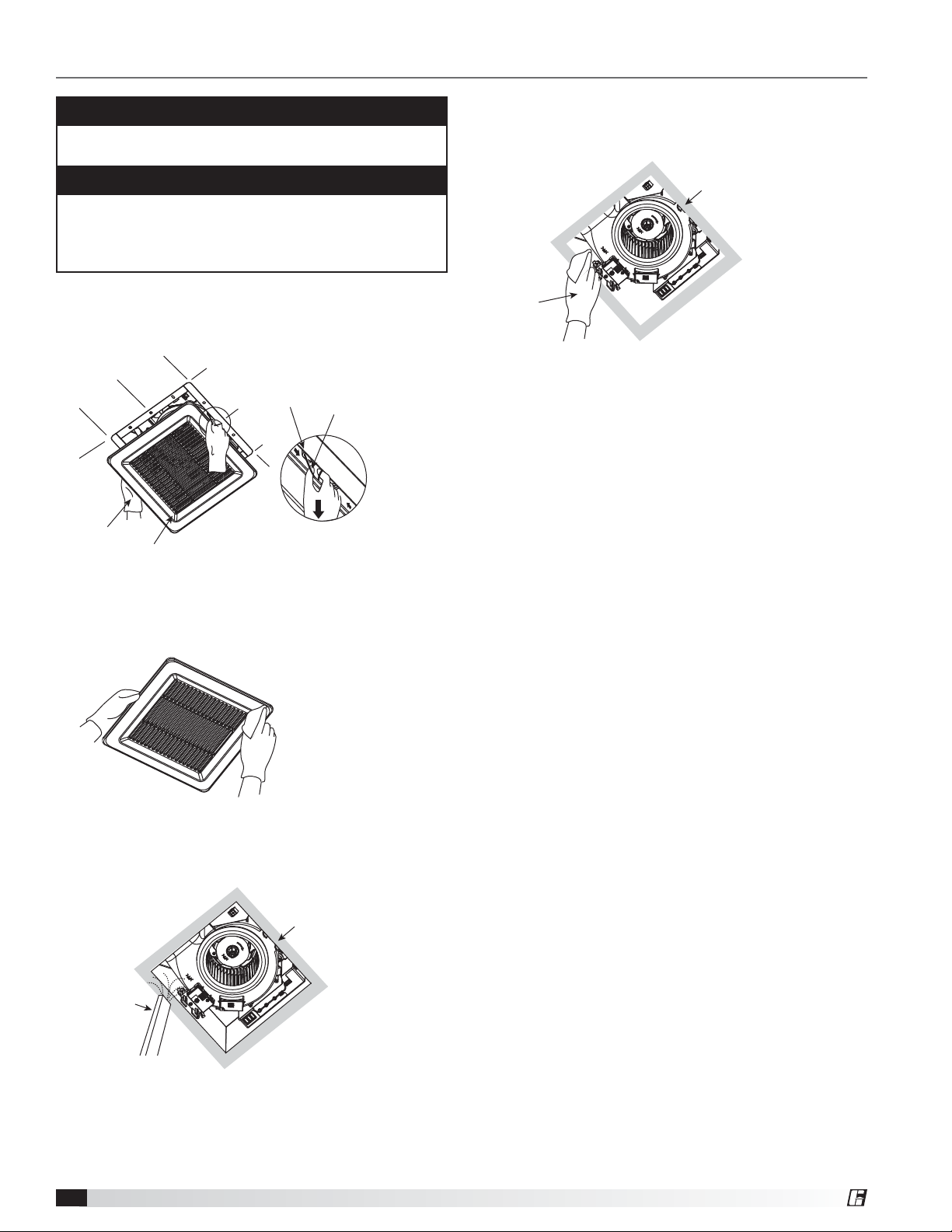
Maintenance
WARNING
Disconnect power source before working on unit
Routine maintenance must be performed annually.
CAUTION
1. Never use gasoline, benzene, thinner or any other
such chemicals for cleaning the ventilating fan.
2. Do not immerse motor in water when cleaning.
3. Do not soak parts in water over 140°F (60°C).
Cleaning
1. Remove grille. Squeeze mounting spring and pull
down carefully. See Fig. 17
Slot
Gloves
Louvers
Fig. 17
Mounting
Spring
5. Using a cloth dampened with kitchen detergent;
remove any dirt from fan body. Wipe dry with clean
cloth. See Fig. 20
Ceiling
Gloves
Fig. 20
6. Reinstall grille.
2. Clean grille. Do not put into hot water. Use nonabrasive kitchen detergent, wipe dry with clean cloth.
See Fig. 18
Fig. 18
4. Remove dust and dirt from fan body using a vacuum
cleaner. See Fig. 19
Ceiling
Vacuum
Cleaner
Fig. 19
Ceiling Exhaust Fans10
®
Page 11
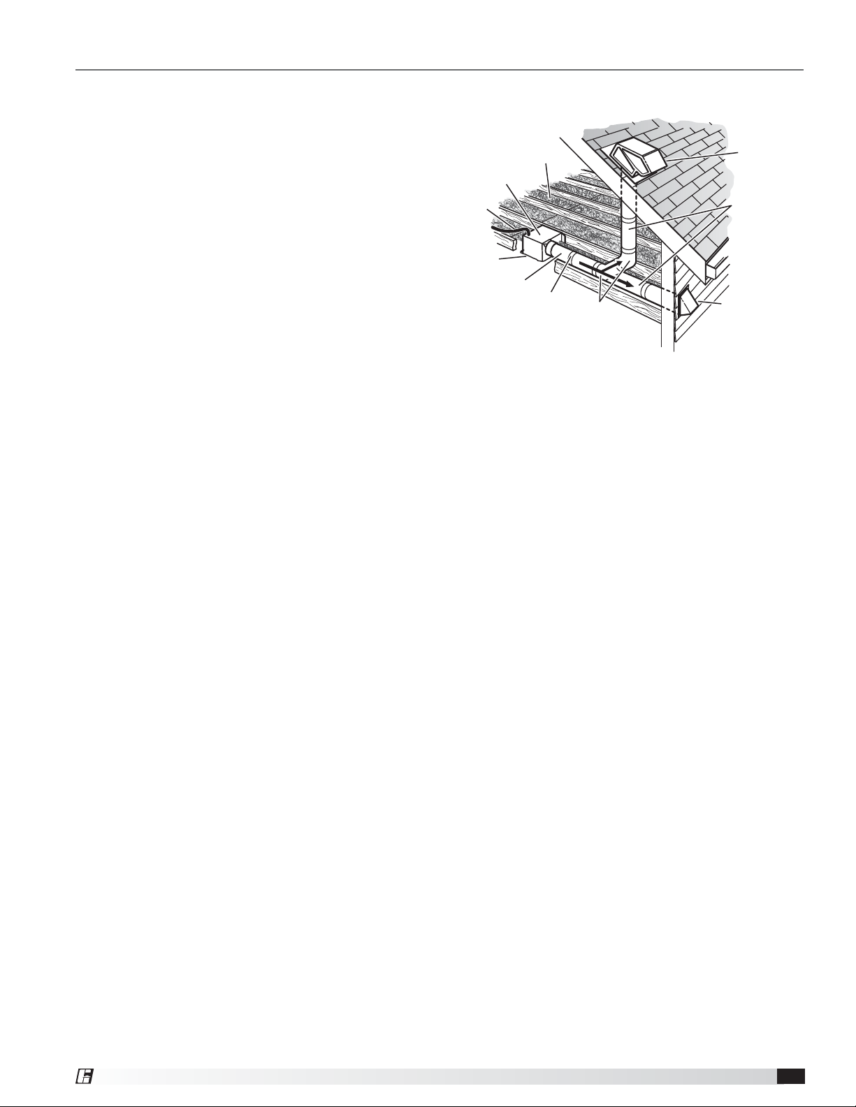
Typical Installation
The ducting from this fan to the outside of the building has a strong effect on the airflow, noise and energy use of
the fan. Use the shortest, straightest duct routing possible for best performance, and avoid installing the fan with
smaller ducts than recommended. Insulation around
the ducts can reduce energy loss and inhibit mold
growth. Fans installed with existing ducts may not
achieve their rated airflow.
Rigid metal duct is recommended for optimal fan
performance.
INSULATION*
(Place around and over Fan Housing.)
FAN HOUSING
POWER CABLE*
Ensure duct joints and exterior penetrations are
sealed with caulk or other similar material to create
an air-tight path and to minimize building heat loss
and gain and reduce the potential for condensation.
Place/wrap insulation around duct and/or fan to in
Seal gaps
around Housing.
ROUND DUCT*
Seal duct joints
with tape.
order to minimize possible condensation buildup
within the duct, as well as minimize building heat
*Purchase separately.
loss and gain.
OR
ROUND
ELBOWS*
ROOF CAP*
(with built-in damper)
Keep duct
runs short.
WALL CAP*
(with built-in damper)
®
Ceiling Exhaust Fans 11
Page 12

Our Commitment
As a result of our commitment to continuous improvement, Greenheck reserves the right to change specifications
without notice.
Product warranties can be found online at Greenheck.com, either on the specific product page or in the literature
section of the website at Greenheck.com/Resources/Library/Literature.
AMCA Publication 410-96, Safety Practices for Users and Installers of Industrial and Commercial Fans, provides additional safety
information. This publication can be obtained from AMCA International, Inc. at www.amca.org.
®
Phone: 715.359.6171 • Fax: 715.355.2399 • Parts: 800.355.5354 • E-mail: [email protected] • Website: www.greenheck.com
483971 • SP-AB, Rev. 1, September 2019 Copyright 2019 © Greenheck Fan Corporation12
 Loading...