

Greenheck SWB 100 Series, SFB Series, SWB 200 Series, SFD Series Installation, Operation And Maintenance Manual
Page 1
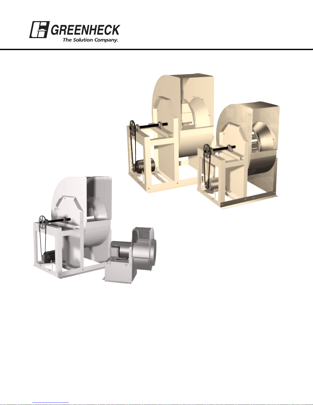
MODEL SFB
MODEL SFD
MODEL SWB
Series 100
MODEL SWB
Series 200
TABLE OF CONTENTS
MOTOR AND DRIVE INSTALLATION (UNITS SHIPPED FROM STOCK) . . . . . . . . . . . . . . . . . . . . . . . . . . . . . 2
INSTALLATION . . . . . . . . . . . . . . . . . . . . . . . . . . . . . . . . . . . . . . . . . . . . . . . . . . . . . . . . . . . . . . . . . . . . . . . 3
EFFECT OF INSTALLATION ON PERFORMANCE . . . . . . . . . . . . . . . . . . . . . . . . . . . . . . . . . . . . . . . . . . . . . 3
UL 762 – RESTAURANT EXHAUST . . . . . . . . . . . . . . . . . . . . . . . . . . . . . . . . . . . . . . . . . . . . . . . . . . . . . . . . 3
PRE-STARTING CHECKS . . . . . . . . . . . . . . . . . . . . . . . . . . . . . . . . . . . . . . . . . . . . . . . . . . . . . . . . . . . . . . . 4
BELT-DRIVE FAN MAINTENANCE . . . . . . . . . . . . . . . . . . . . . . . . . . . . . . . . . . . . . . . . . . . . . . . . . . . . . . . . . 5
BEARING LUBRICATION SCHEDULE . . . . . . . . . . . . . . . . . . . . . . . . . . . . . . . . . . . . . . . . . . . . . . . . . . . . . . 5
MOTOR MAINTENANCE (BELT AND DIRECT DRIVE) . . . . . . . . . . . . . . . . . . . . . . . . . . . . . . . . . . . . . . . . . . 6
PARTS LIST . . . . . . . . . . . . . . . . . . . . . . . . . . . . . . . . . . . . . . . . . . . . . . . . . . . . . . . . . . . . . . . . . . . . . . . . . . 7
TROUBLESHOOTING CHART . . . . . . . . . . . . . . . . . . . . . . . . . . . . . . . . . . . . . . . . . . . . . . . . . . . . . . . . . . . . 8
®
READ AND SAVE THESE INSTRUCTIONS
Centrifugal Utility Fans
Model SWB (Series 100 & 200)
Models SFB and SFD
PN 455308
Installation, Operation and Maintenance Manual
Page 2
2
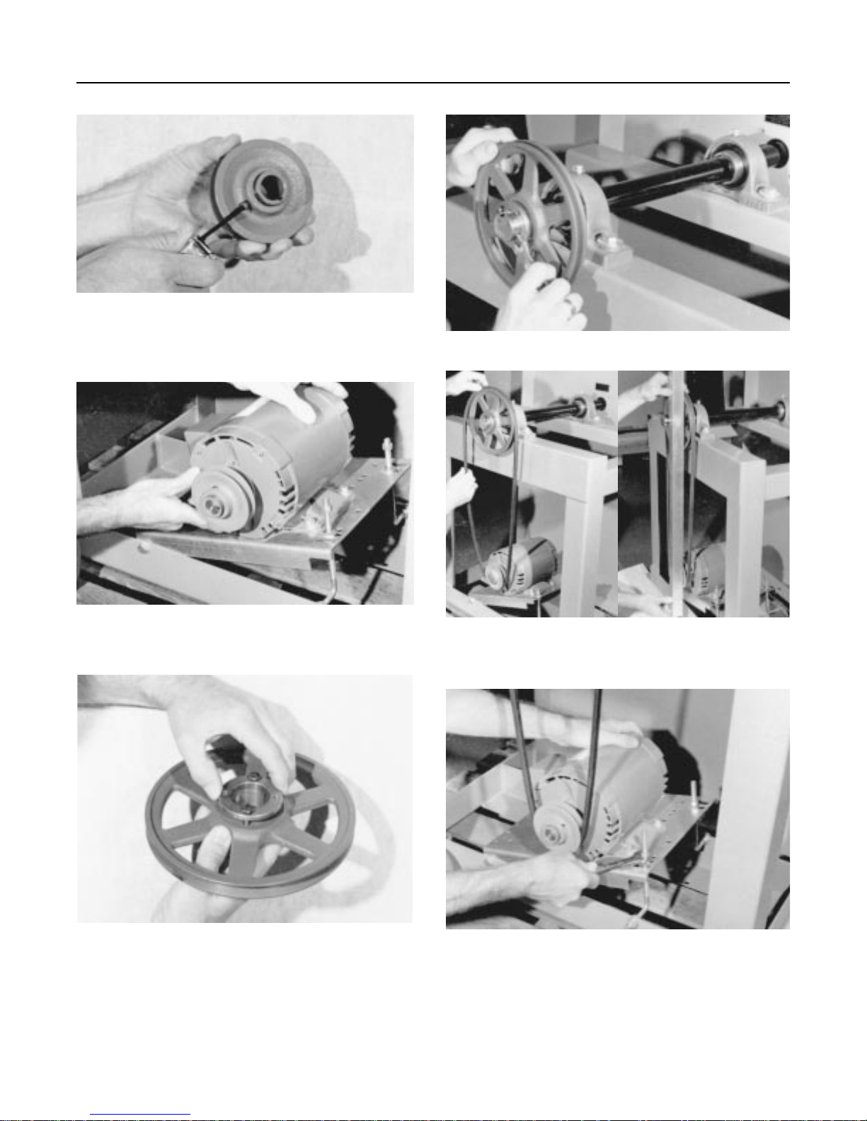
MOTOR AND DRIVE INSTALLATION INSTRUCTIONS
(For Model SWB units shipped from stock without motors or drives)
[ ] 1. Adjust motor pulley to its closed position
for maximum fan speed or increments of 1/2 turn
open (maximum of 5 turns open) for reduced fan
speed. Tighten set screw on flat area only.
[ ] 4. Install shaft pulley to fan shaft.
[ ] 5. Install drive belt(s). Belts should not be
forced over pulleys. Align motor and shaft pulleys
with a straight edge. Tighten all set screws.
[ ] 6. Adjust belt tension. See page 5 for belt
tensioning instructions.
[ ] 2. Install motor pulley to the motor shaft and
install motor to the motor plate. Prepunched holes
are provided for most common motor frame sizes.
[ ] 3. If supplied, install taperlock bushing into
shaft pulley.
Page 3
3
INSTALLATION
Inspect the unit for any damage and report it to the
shipper immediately. Also, check to see that all
accessory items are accounted for.
Move the fan to the desired location and fasten
securely through mounting holes provided in the base
angles. The unit must be set level (Shimming may be
necessary). Flexible duct connections and vibration
isolators should be used where noise is a factor.
The motor voltage and ampere rating must be
checked for compatibility with the electrical supply
prior to final electrical connection. Supply wiring to the
fan must be properly fused and conform to local and
national electrical codes.
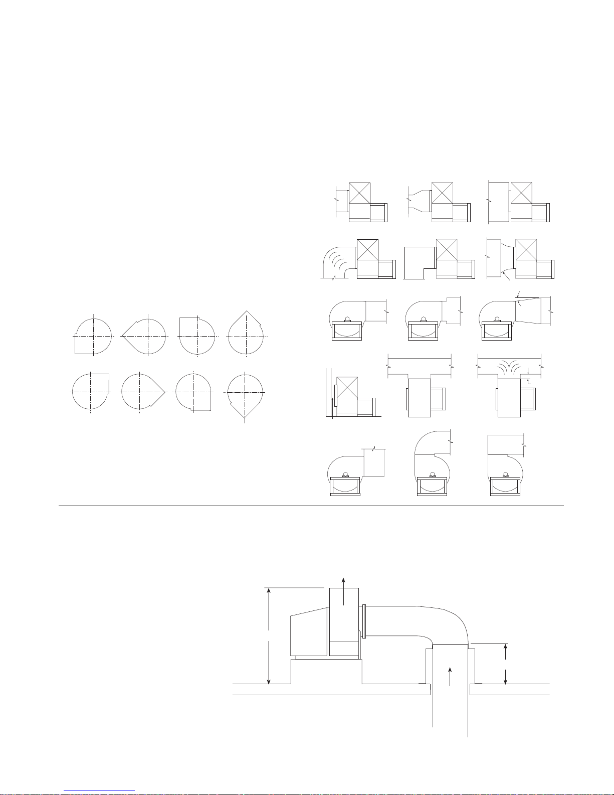
The discharge is factory set as specified by customer
order, however, it can be rotated to other discharge
positions in the field if necessary. Removal of the
housing bolts allows the discharge to be rotated to
the clockwise positions below (Fig. 1). For TAD, BD
and BAD discharge positions a portion of the frame
angle must be removed.
VIEWED FROM DRIVE SIDE OF THE FAN
Fig. 1
Clockwise rotation shown. Counterclockwise
discharge positions are a mirror image of those
shown. The SWB 100 Series is clockwise rotation
only. Fan rotation is always viewed from the drive
side of the housing.
EFFECT OF INSTALLATION
ON PERFORMANCE
Restricted or unstable flow at the fan inlet can cause
pre-rotation of incoming air or uneven loading of the
fan wheel, yielding large system losses, increased
sound levels and structural failure of the fan wheel.
Free discharge or turbulent flow in the discharge
ductwork will also result in system effect losses.
The examples below show the system layout and inlet
and discharge configurations which can affect fan
performance.
INSTALLATION OF UL 762 LISTED FANS FOR RESTAURANT EXHAUST
The UL 762 listing for restaurant exhaust is available on SWB 200 Series fan sizes 10-36 with a weatherhood. UL
762 fans are listed for a maximum operating temperature of 375°F and include a bolted access door and 1" drain
connection. An outlet guard is
strongly recommended when the
fan discharge is accessible. An
upblast discharge is recommended.
The fan discharge must be a
minimum of 40" above the roof
line and the exhaust duct must
be fully welded to a distance of 18"
above the roof surface.
This drawing is for dimensional
information only. See the latest
edition of NFPA 96 Standard for
Ventilation Control and Fire
Protection of Commercial
Cooking Operations for detailed
installation instructions, materials,
duct connections and clearances.
Good Poor Poor
Good
Good Good Good
Poor
Good
Not greater than 60°
included angle
7° Max.
CW BH CW BAU CW TAUCW UB
CW TH CW TAD
CW DB
CW BAD
Poor
Distance should be at
least 1/2 dia.
Poor
Poor
Good
Good
ONE FAN DIA.
Poor
40"**
** Per NFPA 96 the fan discharge
must be a minimum of 40"
above the roof surface.
Weatherhood
Upblast Discharge
A 96 the duct must be
Duct
From
Kitchen
Hood
18"*
* Per NFP
all welded construction to a
minumum distance of 18"
above the roof surface.
Page 4
Unit
Size
6 - - - 3/8 7 - - - 3/8 -
9 - - - 1/2 1/2
10 3/8 1/4 5/32 1/2 1/2
12 3/8 - 5/32 - 1/2
13 7/16 1/4 5/32 - 1/2
15 1/2 1/4 5/32 - 1/2
16 1/2 1/4 5/32 - 18 5/8 3/8 5/32 - 1/2
20 5/8 3/8 5/32 - 5/8
22 11/16 - 5/32 - 5/8
24 3/4 3/8 5/32 - 25 - - - - 3/4
27 7/8 - 3/16 - 3/4
30 15/16 1/2 3/16 - 3/4
33 1-1/16 - 3/16 - 36 1-3/16 1/2 3/16 - -
4
PRE-STARTING CHECKS
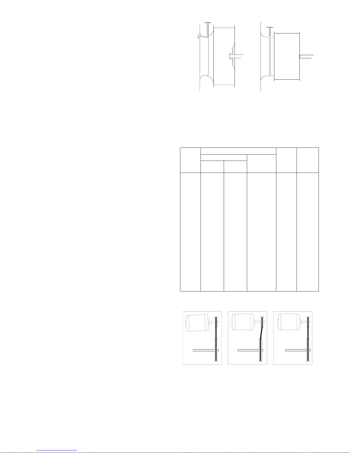
Wheels must rotate freely and not rub on the inlet
venturi. Model SWB wheels overlap the inlet venturi
as shown in Figure 2. Refer to the SWB fan wheel
overlap and radial gap chart for proper dimensions.
Models SFD and SFB wheels do not overlap the
venturi, but have a gap between the inlet venturi and
the wheel (Fig. 3). Wheel position is preset at the
factory and the unit is test run. Wheel movement
may occur during shipment or installation and wheel
alignment may be necessary.
On belt drive units, centering can be accomplished
by (1) loosening the inlet cone bolts to move the
inlet cone or by (2) loosening the bearings in order
to move the shaft. Wheel and inlet cone overlap can
be adjusted by loosening the wheel hub set screw
and moving the wheel to the desired position.
Tighten all fasteners and set screws securely and
realign drive pulleys after adjustment. Check pulleys
and belts for proper alignment to avoid unnecessary
belt wear, noise, vibration and power loss. Motor
and drive shafts must be parallel and pulleys in line
(Fig. 4)
The adjustable motor pulley is set at the factory for
the fan RPM specified by the customer. Fan RPM
can be increased by closing or decreased by
opening the adjustable motor pulley. Multi-groove
variable pitch pulleys must be adjusted an equal
number of turns open or closed. Any increase in fan
speed represents a substantial increase in load on
the motor.
To avoid motor overheating and possible burnout,
motor load amperes should always be checked and
compared to nameplate rating when fan speed is
increased.
Rotation direction of the wheel is critical and
incorrect rotation will result in reduced air
performance, increased motor loading and possible
motor burnout.
MODEL SWB
Fig. 2
Wrong Wrong Right
Fig. 4
APPROXIMATE WHEEL CLEARANCE DIMENSIONS
Overlap (inches)
Series
100
Series
200
Radial Gap
(inches)
SWB
SFD
GAP
(in.)
SFB
GAP
(in.)
MODEL SFD OR SFB
Fig. 3
Radial
Gap
Overlap
Wheel
Gap
Wheel
Page 5
5
BLOWER MAINTENANCE (BELT DRIVE)
Belts tend to stretch after a period of time. They
should be periodically checked for tension and
wear. When replacing belts, use the same type as
supplied with the unit. Replacement of belts should
be accomplished by loosening the tensioning “Lbolts” so the belts may be removed by hand. Do not
force belts on or off as this may cause breakage of
cords and lead to premature belt failure.
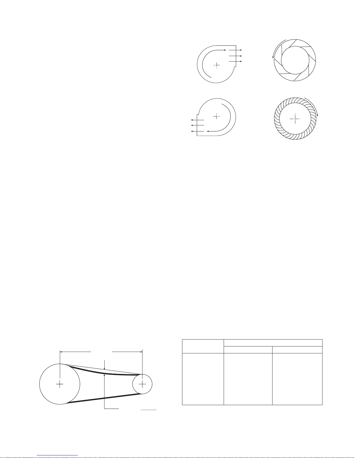
Belt tension should be adjusted to allow 1/64" of
belt deflection per 1" of belt span. For example, a
16" belt span should have 16/64" or 1/4" of
deflection with moderate thumb pressure at midpoint between the pulleys. (Fig. 6).
Shaft bearings are the most critical moving part of a
fan. Therefore, special attention should be given to
keeping the bearings clean and well lubricated.
Proper lubrication provides for reduction in friction
and wear, transmission and dissipation of heat,
extended bearing life and prevention of rust.
In order for a lubricant to fulfill these tasks, the
proper grease applied at regular intervals is
required. See the recommended bearing lubrication
schedule.
Check wheel rotation by momentarily
energizing the unit and noting if rotation is in
the same direction as the airflow at the outlet
and conforms to the rotation decal affixed to
the unit (Fig. 5). NOTE: Models SFD and SFB
units should be operated only when attached
to the system for which they were designed.
Without proper system static pressure the
motor could be seriously overloaded.
***************************************************************************
WARNING
DISCONNECT AND SECURE TO THE “OFF” POSITION ALL ELECTRICAL POWER TO THE FAN PRIOR
TO INSPECTION OR SERVICING. FAILURE TO COMPLY WITH THIS SAFETY PRECAUTION COULD
RESULT IN SERIOUS INJURY OR DEATH.
***************************************************************************
Fig. 6
BEARING LUBRICATION SCHEDULE
FOR GREENHECK UTILITY FANS
(Relubrication schedule in months)
Fig. 5
WHEELS VIEWED FROM
THE DRIVE SIDE
FAN RPM
To 500 6 6
500-1000 6 5
1000-1500 5 4
1500-2000 4 3
2000-2500 4 2
2500-3000 3 1
3000-3500 2 1
3/4 to 1 1/2 1 3/4 to 2
Shaft Diameter in inches
Airflow
Backward Inclined
n
o
i
t
a
t
o
R
n
Airflow
R
o
t
a
t
i
o
t
io
ta
o
n
R
Forward Curved
t
io
ta
o
n
R
Belt Span
Deflection =
Belt Span
64
Page 6

6
If unusual conditions exist - temperatures below
32°F or above 200°F, moisture or contaminants more frequent lubrication is required.
With the unit running add grease very slowly with a
manual grease gun until a slight bead of grease
forms at the seal.
Be careful not to unseat the seal by over lubricating
or using excessive pressure. A guide to the amount
of grease to be used is to fill 30% to 60% of
available space in the bearing and housing.
A high quality lithium based grease conforming to
NLGI Grade 2 consistency, such as those listed
below, should be used.
Mobil 532
Mobilux #2
B Shell Alvania #2
Texaco Multifak #2
Texaco Premium #2
Unirex N2
In addition to lubricating the bearings at specified
intervals, set screws in the bearing collars should be
checked for tightness. A bearing collar which has
loosened will cause premature failure of the fan
shaft. Fasteners attaching the bearings to the drive
frame should also be checked.
MOTOR MAINTENANCE
(BELT AND DIRECT DRIVE)
Motor maintenance is generally limited to cleaning
and lubrication (where applicable). Cleaning should
be limited to exterior surfaces only. Removing dust
and grease build-up on the motor housing assures
proper motor cooling. Use caution and do not allow
water or solvents to enter the motor or bearings.
Under no circumstances should motors or bearings
be sprayed with steam, water or solvents.
Greasing of motors is intended only when fittings
are provided. Many fractional horsepower motors
are permanently lubricated for life and require no
further lubrication. Motors supplied with grease
fittings should be greased in accordance with the
manufacturer’s recommendations.
WHEEL AND FASTENER
MAINTENANCE
Wheels require very little attention when exhausting
clean air, however air heavily laden with grease or
dirt will tend to accumulate on the wheel causing
unbalance. Wheels exhausting dirty or grease laden
air require frequent cleaning to assure smooth and
safe operation.
All fasteners, including set screws in the bearing
collars, should be checked for tightness each time
maintenance checks are performed.
A proper maintenance program will help preserve
the performance and reliability designed into the
fan.
Page 7
7
PARTS LIST
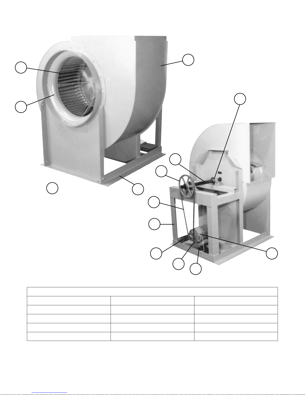
Always provide the unit model and serial number when requesting parts or information.
REPLACEMENT PARTS
1. Scroll housing
2. Drive frame - Base angle
3. Intake support panel
4. Inlet ring and cone
5. Wheel (Specify rotation)
6. Drive frame assembly
7. Pillow block bearings
8. Fan shaft
9. Shaft pulley
10. Belt
11. Motor pulley
12. Belt tensioning bolts
13. Motor plate
14. Motor
1
2
3
4
5
7
8
9
10
6
11
13
12
14
Page 8
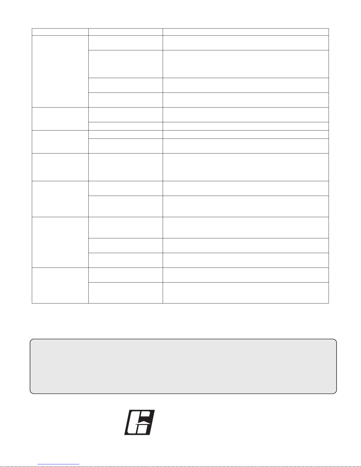
Problem
Excessive
Noise
Low
CFM
High
CFM
Static
Pressure
Wrong
High
Horsepower
Fan
Doesn’t
Operate
Overheated
Bearing
NOTE: Always provide the unit model and serial numbers when requesting parts or service information.
*Always check motor amps and compare to nameplate rating. Excessive fan speed may overload the motor
and result in burnout.
IOM SWB/SFB/SFD FS
Rev. 2 February 2001
Wheel Rubbing Inlet
Adjust wheel and/or inlet cone. Tighten wheel
hub or bearing collars on shaft.
V-Belt Drive
Tighten sheaves on motor/fan shaft. Adjust
belt tension. Align sheaves properly
(see page 4). Replace worn belts
or sheaves.
Bearings
Replace defective bearing(s). Lubricate
bearings. Tighten collars & fasteners.
Wheel Unbalance
Clean all dirt off wheel. Check wheel
balance, rebalance in place if necessary.
Fan
Check wheel for correct rotation.
Increase fan speed.*
Duct System
See page 3.
Fan
Decrease fan speed.
Duct System
Resize ductwork. Access door,
filters, grills not installed.
Duct system has
more or less
restriction than
anticipated
Change obstructions in system. Use
correction factor to adjust for
temperature/altitude. Resize ductwork.
Clean filters/coils. Change fan speed.*
Fan
Check rotation of wheel. Reduce
fan speed.
Duct
System
Resize ductwork. Check proper operation
of face and bypass dampers. Check
filters and access doors.
Electrical
Supply
Check fuses/circuit breakers. Check for
switches off. Check for correct
supply voltage.
Drive
Check for broken belts. Tighten
loose pulleys.
Motor
Assure motor is correct horsepower
and not tripping overload protector.
Lubrication
Check for excessive or insufficient grease
in the bearing.
Mechanical
Replace damaged bearing. Relieve excessive
belt tension. Align bearings.
Check for bent shaft.
Cause Corrective Action
8
TROUBLESHOOTING
GREENHECK
P.O. BOX 410 SCHOFIELD, WISCONSIN 54476-0410
PH. 715-359-6171
www.greenheck.com
®
Warranty
Greenheck warrants this equipment to be free from defects in material and workmanship for a period of one year from the
purchase date. Any units or parts which prove defective during the warranty period will be replaced at our option when returned
to our factory, transportation prepaid.
Motors are warranted by the motor manufacturer for a period of one year. Should motors furnished by Greenheck prove defective
during this period, they should be returned to the nearest authorized motor service station. Greenheck will not be responsible for
any removal or installation costs.
Copyright © 2001 Greenheck Fan Corp.
 Loading...