

Page 1
Document 472846
Heat Recovery Ventilators
®
Installation, Operation and Maintenance Manual
Please read and save these instructions. Read carefully before attempting to assemble, install, operate or maintain the
product described. Protect yourself and others by observing all safety information. Failure to comply with instructions
could result in personal injury and/or property damage! Retain instructions for future reference.
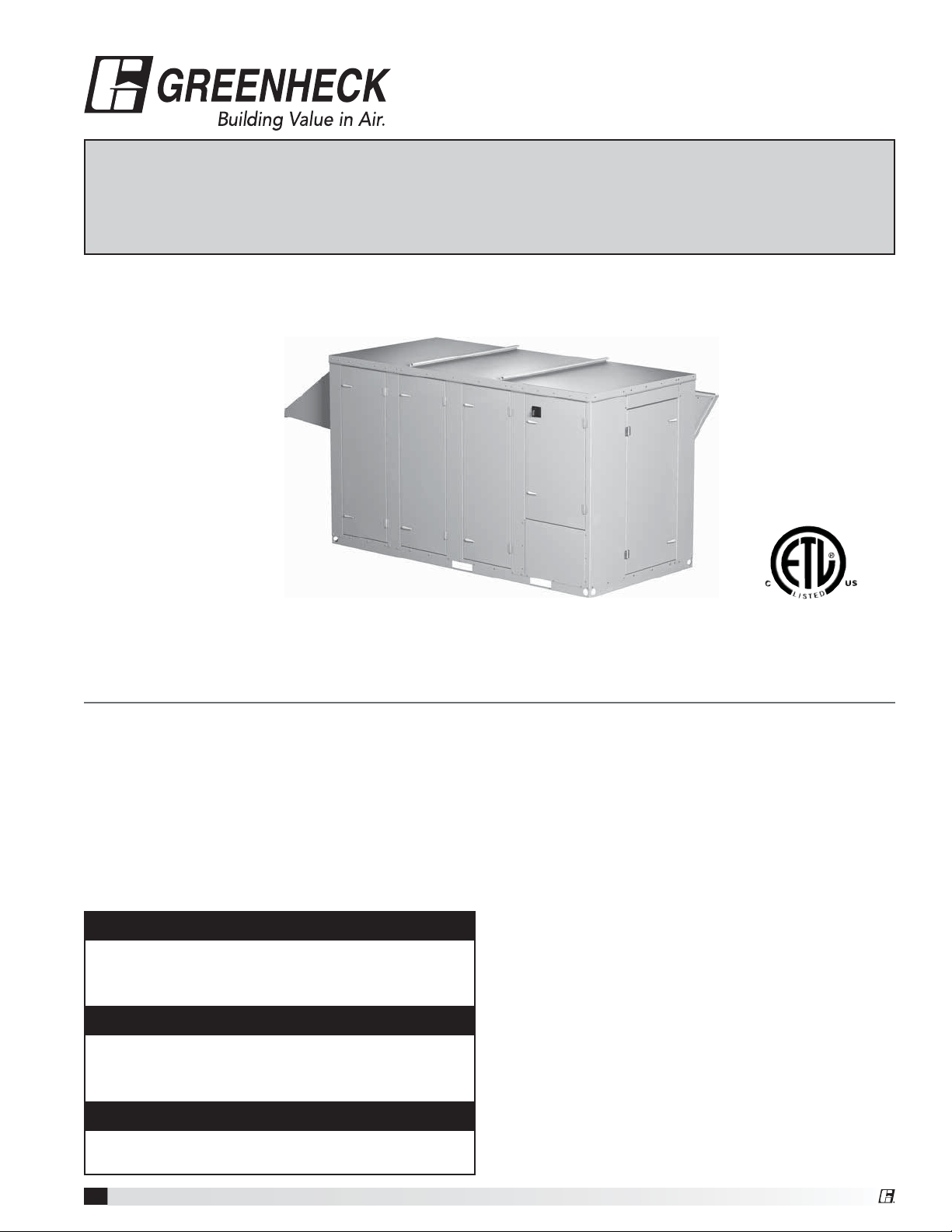
Model PVe
General Safety Information
Only qualified personnel should install this system.
Personnel should have a clear understanding of these
instructions and should be aware of general safety
precautions. Improper installation can result in electric
shock, possible injury due to coming in contact with
moving parts, as well as other potential hazards. Other
considerations may be required if high winds or seismic
activity are present. If more information is needed,
contact a licensed professional engineer before moving
forward.
DANGER
Always disconnect power before working on or near
this equipment. Lock and tag the disconnect switch or
breaker to prevent accidental power up.
CAUTION
When servicing the unit, the internal components may
be hot enough to cause pain or injury. Allow time for
cooling before servicing.
CAUTION
Precaution should be taken in explosive atmospheres.
1. Follow all local electrical and safety codes, as well
as the National Electrical Code (NEC), the National
Fire Protection Agency (NFPA), where applicable.
Follow the Canadian Electric Code (CEC) in
Canada.
2. All moving parts must be free to rotate without
striking or rubbing any stationary objects.
3. Unit must be securely and adequately grounded.
4. Do not spin fan wheel faster than maximum
cataloged fan RPM. Adjustments to fan speed
significantly affects motor load. If the fan RPM is
changed, the motor current should be checked to
make sure it is not exceeding the motor nameplate
amps.
5. Do not allow the power cable to kink or come in
contact with oil, grease, hot surfaces or chemicals.
Replace cord immediately if damaged.
6. Verify that the power source is compatible with the
equipment.
7. Never open access doors to the unit while it is
running.
Model PVe Heat Recovery Unit
1
Page 2

Receiving
Upon receiving the product check to make sure all
items are accounted for by referencing the bill of lading
to ensure all items were received. Inspect each crate
for shipping damage before accepting delivery. Notify
the carrier if any damage is noticed. The carrier will
make notification on the delivery receipt acknowledging
any damage to the product. All damage should be
noted on all the copies of the bill of lading which
is countersigned by the delivering carrier. A Carrier
Inspection Report should be filled out by the carrier
upon arrival and reported to the Traffic Department.
If damaged upon arrival, file claim with carrier. Any
physical damage to the unit after acceptance is not the
responsibility of manufacturer.
Unpacking
Verify that all required parts and the correct quantity
of each item have been received. If any items are
missing, report shortages to your local representative to
arrange for obtaining missing parts. Sometimes it is not
possible that all items for the unit be shipped together
due to availability of transportation and truck space.
Confirmation of shipment(s) must be limited to only
items on the bill of lading.
Handling
Units are to be rigged and moved by the lifting brackets
provided or by the skid when a forklift is used. Location
of brackets varies by model and size. Handle in such
a manner as to keep from scratching or chipping the
coating. Damaged finish may reduce ability of unit to
resist corrosion.
Storage
Units are protected against damage during shipment. If
the unit cannot be installed and operated immediately,
precautions need to be taken to prevent deterioration of
the unit during storage. The user assumes responsibility
of the unit and accessories while in storage. The
manufacturer will not be responsible for damage during
storage. These suggestions are provided solely as a
convenience to the user.
INDOOR — The ideal environment for the storage of
units and accessories is indoors, above grade, in a
low humidity atmosphere which is sealed to prevent
the entry of blowing dust, rain, or snow. Temperatures
should be evenly maintained between 30°F (-1°C) and
110°F (43°C) (wide temperature swings may cause
condensation and “sweating” of metal parts). All
accessories must be stored indoors in a clean, dry
atmosphere.
Remove any accumulations of dirt, water, ice, or snow
and wipe dry before moving to indoor storage. To avoid
“sweating” of metal parts allow cold parts to reach
room temperature. To dry parts and packages use a
portable electric heater to get rid of any moisture build
up. Leave coverings loose to permit air circulation and
to allow for periodic inspection.
The unit should be stored at least 3½ in. (89 mm) off
the floor on wooden blocks covered with moisture proof
paper or polyethylene sheathing. Aisles between parts
and along all walls should be provided to permit air
circulation and space for inspection.
OUTDOOR — Units designed for outdoor applications
may be stored outdoors, if absolutely necessary. Roads
or aisles for portable cranes and hauling equipment are
needed.
The fan should be placed on a level surface to prevent
water from leaking into the unit. The unit should be
elevated on an adequate number of wooden blocks so
that it is above water and snow levels and has enough
blocking to prevent it from settling into soft ground.
Locate parts far enough apart to permit air circulation,
sunlight, and space for periodic inspection. To minimize
water accumulation, place all unit parts on blocking
supports so that rain water will run off.
Do not cover parts with plastic film or tarps as these
cause condensation of moisture from the air passing
through heating and cooling cycles.
Inspection and Maintenance during
Storage
While in storage, inspect fans once per month. Keep a
record of inspection and maintenance performed.
If moisture or dirt accumulations are found on parts,
the source should be located and eliminated. At each
inspection, rotate the fan wheel by hand ten to fifteen
revolutions to distribute lubricant on motor. Every three
months, the fan motor should be energized. If paint
deterioration begins, consideration should be given to
touch-up or repainting. Fans with special coatings may
require special techniques for touch-up or repair.
Machined parts coated with rust preventive should be
restored to good condition promptly if signs of rust
occur. Immediately remove the original rust preventive
coating with petroleum solvent and clean with lintfree cloths. Polish any remaining rust from surface
with crocus cloth or fine emery paper and oil. Do not
destroy the continuity of the surfaces. Wipe thoroughly
clean with Tectyl® 506 (Ashland Inc.) or the equivalent.
For hard to reach internal surfaces or for occasional
use, consider using Tectyl® 511M Rust Preventive or
WD-40
REMOVING FROM STORAGE — As units are removed
from storage to be installed in their final location, they
should be protected and maintained in a similar fashion,
until the equipment goes into operation.
Prior to installing the unit and system components,
inspect the unit assembly to make sure it is in working
order.
1. Check all fasteners, set screws on the fan, wheel,
2. Rotate the fan wheel(s) by hand and assure no parts
® or the equivalent.
bearings, drive, motor base, and accessories for
tightness.
are rubbing.
Model PVe Heat Recovery Unit
2
Page 3
OUTDOOR
Table of Contents
Product Overview
Product Overview . . . . . . . . . . . . . 3
Installation
Unit Dimensions and Weights . . . . . . . . 4
Access Panel Description and Locations . . . 4
Service Clearances . . . . . . . . . . . . 5
Handling . . . . . . . . . . . . . . . . . 5
Lifting . . . . . . . . . . . . . . . . . . 5
Roof Curb Mounting . . . . . . . . . . . . 6
Curb Outside Dimensions and Weights . . . . 6
Rail Mounting/Layout . . . . . . . . . . . 7
Ductwork Connections . . . . . . . . . . . 7
Electrical Installation
General Electrical Information . . . . . . . . 8
Field-Provided Disconnect . . . . . . . . . 9
Discharge Air Temperature Sensor . . . . . . 9
Control Center Components . . . . . . . . . 9
Optional Accessory Wiring Schematics . . . . 10
Piping Installation
Condensate Drain Trap . . . . . . . . . . . 11
Unit Overview . . . . . . . . . . . . . . . 11
Optional Component Overview
Economizer . . . . . . . . . . . . . . . 12
Frost Control . . . . . . . . . . . . . . . 12
Variable Frequency Drives . . . . . . . . . 12
CO
Sensor . . . . . . . . . . . . . . . 12
2
Dirty Filter Sensor . . . . . . . . . . . . . 12
Service Outlet . . . . . . . . . . . . . . 12
Vapor Tight Lights . . . . . . . . . . . . . 12
Unit Start-Up
General . . . . . . . . . . . . . . . . . 13
Special Tools Required . . . . . . . . . . . 13
Start-Up Procedure . . . . . . . . . . . . 13
Voltage Imbalance . . . . . . . . . . . . . 13
Pre Start-Up Checklist . . . . . . . . . . . 13
Start-Up Checklist. . . . . . . . . . . . . 14
Optional Accessories Checklist . . . . . . . 14
Start-Up Components
Fans . . . . . . . . . . . . . . . . . . 15
Vibrations . . . . . . . . . . . . . . . .16
Optional Start-Up Components
Dirty Filter Switch . . . . . . . . . . . . . 16
Frost Control . . . . . . . . . . . . . . . 16
Variable Frequency Drives . . . . . . . . 17-18
Routine Maintenance Checklist
Overview. . . . . . . . . . . . . . . . . 19
General . . . . . . . . . . . . . . . . . 19
Procedures. . . . . . . . . . . . . . 20-21
Parts List . . . . . . . . . . . . . . . . . 21
Troubleshooting
Airflow. . . . . . . . . . . . . . . . . . 22
Unit . . . . . . . . . . . . . . . . . . . 23
Maintenance Log . . . . . . . . . Backcover
Our Commitment . . . . . . . . . Backcover
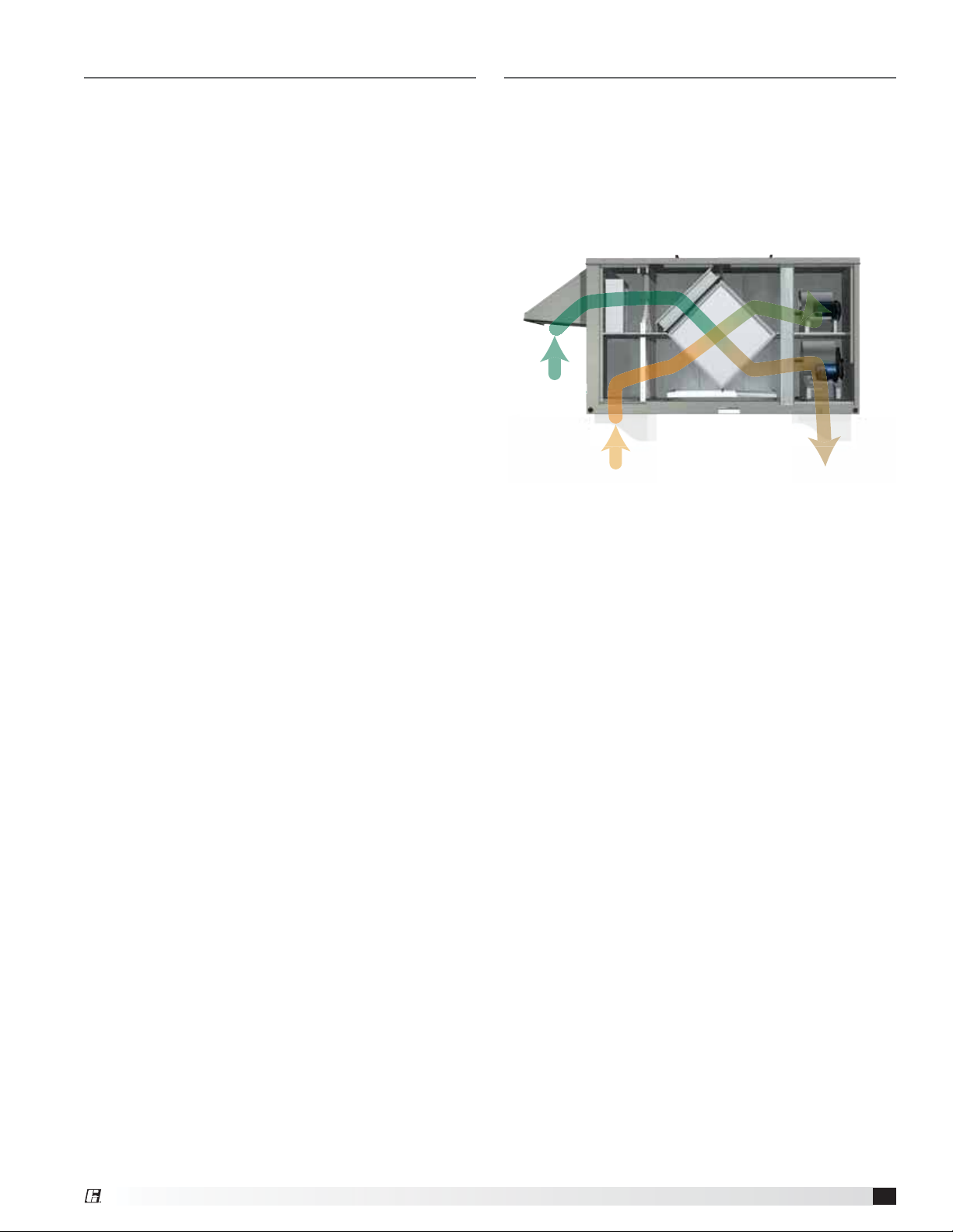
The unit brings in fresh outdoor air and removes stale
exhaust air from the building. Prior to discharging the
exhaust air, the plate heat exchanger transfers energy
from the exhaust air to the incoming outdoor air. When
used in the cooling mode, heat energy is transferred
from incoming outdoor air to the exhaust air. Simply
put, this unit preconditions the outdoor air to save
money on heating and cooling costs.
AIR
SIDE VIEW
RETURN DUCT
SUPPLY DUCT
Model PVe Heat Recovery Unit
3
Page 4
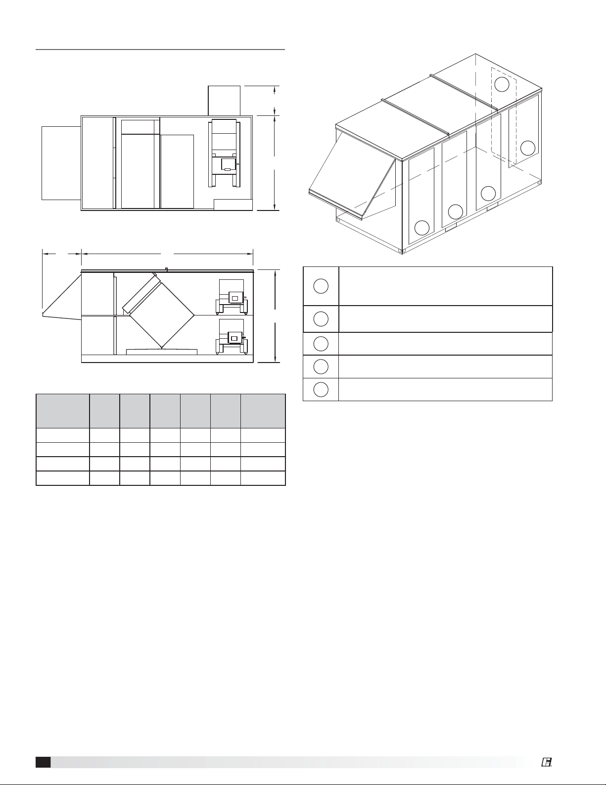
Installation
Unit Dimensions and Weights
Bypass
Damper
Outdoor Air Hood
Outdoor
Air Hood
Face
Filters
Damper
FiltersFilters
Face/Bypass Damper
Plate Heat
Exchanger
Top view
AD
Plate Heat
Exchanger
Exhaust
Air Hood
Control Center
Access Panel Description and Location
5
E
4
C
3
2
1
Filters
1
B
2
Optional OA (Outdoor Air) Damper
Optional RA (Return Air) Damper
Optional Face and Bypass Dampers
Plate Heat Exchanger
Side view
Approx.
Unit Size A B C D E
Weight
PVe-20 104.1 59.7 41.5 20.3 20.7 1300
PVe-35 104.1 59.7 49.2 25.2 17.7 1600
PVe-45 110.6 59.7 61.1 25.2 19.0 2100
PVe-55 116.5 59.7 76.1 25.2 23.8 2700
All dimensions are shown in inches.
(lbs.)
3
4
5
Plate Heat Exchanger
Control Center
Blowers
Model PVe Heat Recovery Unit
4
Page 5
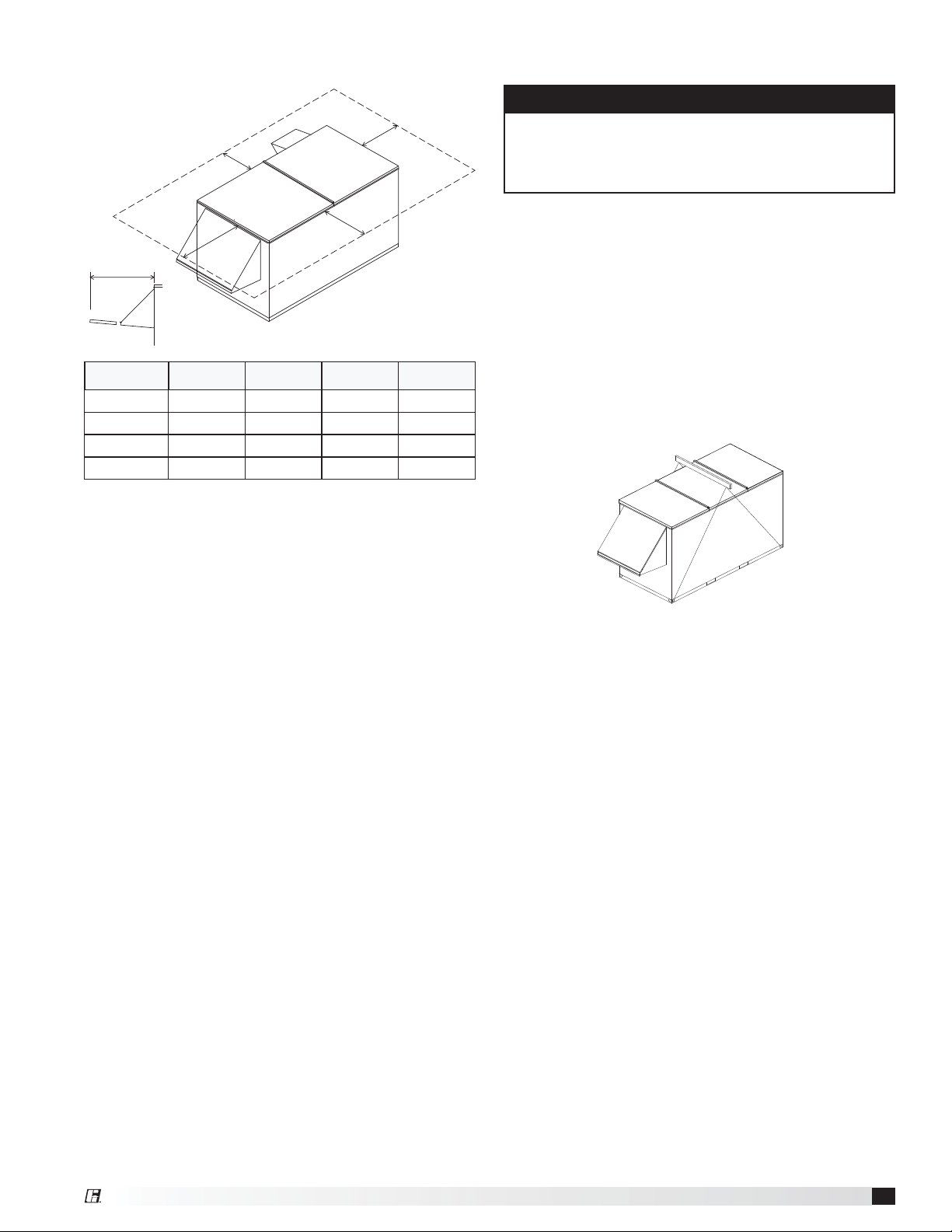
Service Clearances
B
CLEARANCE
C
CLEARANCE
D
D
Unit Size A B C D
PVe-20 36 36 36 60
PVe-35 48 36 36 60
PVe-45 60 36 36 60
PVe-55 72 36 36 60
All dimensions are shown in inches. The weatherhoods
include 2-inch aluminum mesh filters that are removed
out of the end of the hood as shown in this drawing and
require extra clearance for removal.
A
Lifting
WARNING
All factory-provided lifting lugs must be used when
lifting the units. Failure to comply with this safety
precaution could result in property damage, serious
injury, or death.
1. Before lifting, be sure that all shipping material has
been removed from unit.
2. To assist in determining rigging requirements,
weights are provided in the Installation, Unit
Dimensions and Weights section of this manual.
3. Unit must be lifted by all lifting lugs provided on
base structure.
4. Rigger to use suitable mating hardware to attach to
unit lifting lugs.
5. Spreader bar(s) must span the unit to prevent
damage to the cabinet by the lift cables.
Handling
While this unit was constructed with quality and
dependability in mind, damage still may occur during
handling of the unit for installation. Exercise extreme
caution to prevent any damage from occurring to the
refrigerant system. This unit could contain a system
pressurized with refrigerant that, if damaged, could
leak into the atmosphere or cause bodily harm due to
the extreme cold nature of expanding refrigerant. Use
protective equipment such as gloves and safety glasses
to minimize or prevent injury in case of a system leak
during installation.
The system design and installation should follow
accepted industry practice, such as described in
the ASHRAE Handbook. Adequate space should be
left around the unit for piping coils and drains, filter
replacement, and maintenance. Sufficient space
should be provided on the side of the unit for routine
service and component removal should that become
necessary.
6. Always test-lift the unit to check for proper balance
and rigging before hoisting to desired location.
7. Never lift units by weatherhoods.
8. Never lift units in windy conditions.
9. Preparation of curb and roof openings should be
completed prior to lifting unit to the roof.
10. Check to be sure that gasketing (supplied by
others) has been applied to the curb prior to lifting
the unit and setting on curb.
Lifting with a Forklift
Unit base rail includes forklift lifting locations. Use
weights in the Installation, Unit Dimensions and
Weights section of this manual to determine forklift size
requirements.
Model PVe Heat Recovery Unit
5
Page 6
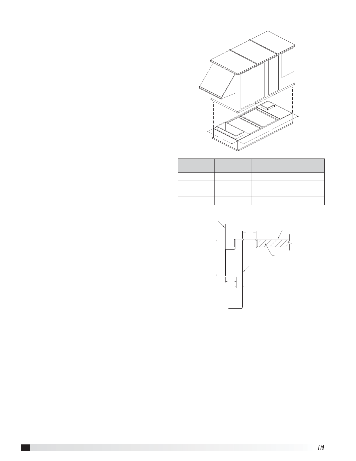
Rooftop units require curbs to be mounted first, in
accordance with their appropriate instructions. Curb
unit is to be installed and then duct connections are to
be made prior to setting of the unit.
Position the unit roof opening such that the supply
discharge and exhaust inlet of the unit will line up with
the corresponding ductwork. Be sure to allow for the
recommended service clearances when positioning
opening.
Do not face the outdoor air intake of the unit into
prevailing wind and keep the intake away from any
other exhaust fans. Likewise, position the exhaust
discharge opening away from outdoor air intakes of any
other equipment.
1. Factory Supplied Roof Curbs: Roof curbs are
Model GKD. The GKD ships in a knockdown kit
(which includes duct adapter) and requires field
assembly by others. Assembly instructions are
included with the GKD curbs.
2. Install Curb: Locate the assembled curb over roof
opening and verify precise location of curb relative
to the roof opening, in accordance with dimensions
given previously. Fasten curb loosely in place and
then shim as needed to ensure a level installation.
Tighten roof fastening hardware and then recheck
for level. Verify that diagonal dimensions of installed
curb are plus or minus 1/8-inch of each other.
3. Install Ductwork: Install needed ductwork in
accordance with SMACNA and AMCA guidelines.
Duct adapter is provided to support ducts prior to
setting the unit.
4. Install Insulation: One-inch deep insulation
pans are provided with the curb assembly. Set the
insulation pans per instructions and then install
insulation in the pans prior to setting the unit.
Insulation is not provided by the unit manufacturer, it
is to be supplied by others.
5. Set the Unit: Lift unit to a point directly above the
curb and duct openings. Guide unit carefully while
lowering in order to align with duct openings. The
roof curb will seat in a recess in the base of the unit.
Verify that the unit is properly seated on the curb and
is level.
Curb Outside Dimensions and WeightsRoof Curb Mounting
L
W
Unit Size L W
PVe-20 99.4 36.8 195
PVe-35 99.4 44.6 216
PVe-45 105.9 56.3 261
PVe-55 111.7 71.3 316
All dimensions are shown in inches.
Unit Side
1.895
4.844
Roof Curb
1.549
0.775
Dimensions are shown in inches.
Curb Cap Details for Factory Supplied Roof Curbs
Unit Base
Insulation Pan
Curb Weight
(lbs.)
Model PVe Heat Recovery Unit
6
Page 7
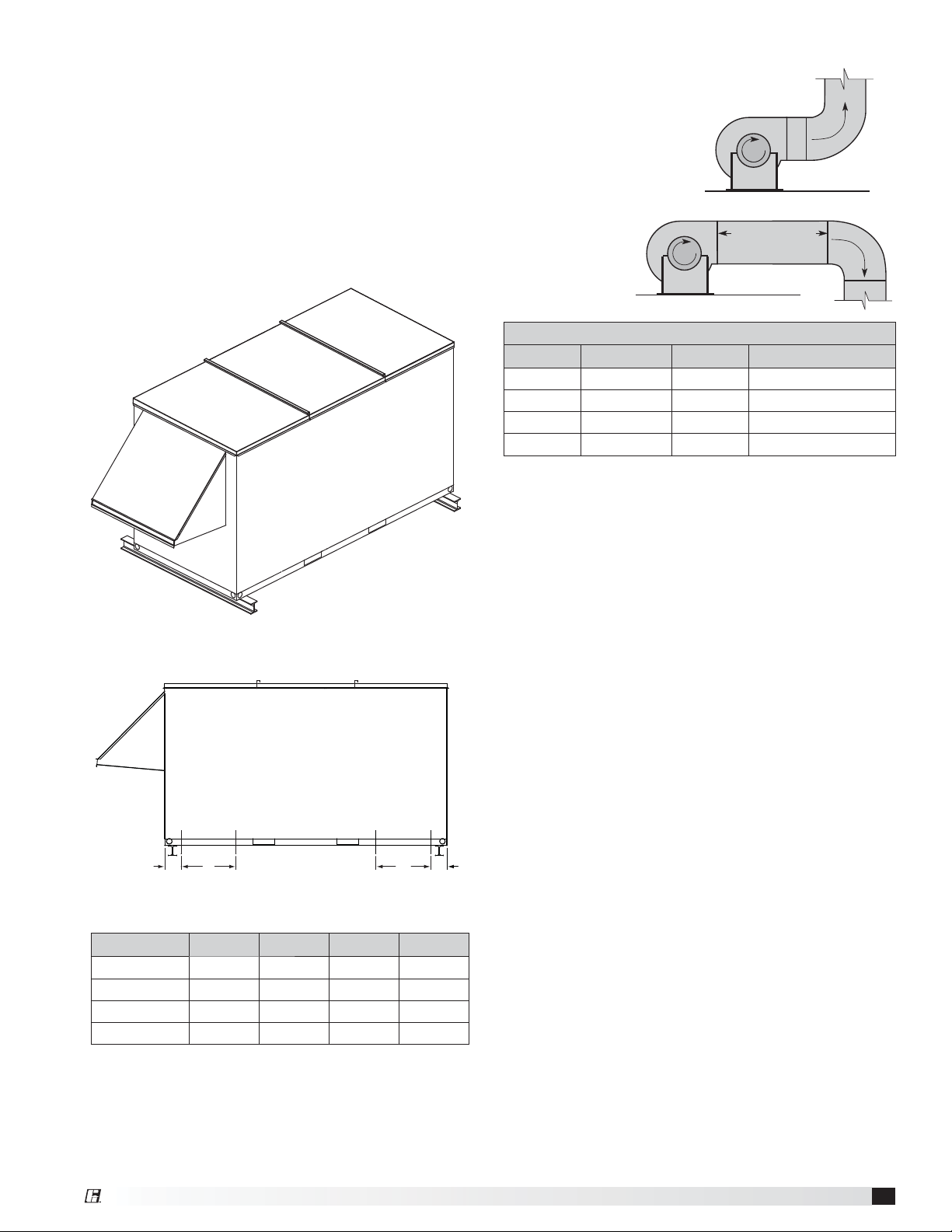
Rail Mounting / Layout
R
o
t
a
t
i
o
n
POOR
1. Rails designed to handle the weight of the unit
should be positioned as shown on the diagram (rails
by others).
2. Make sure that rail positioning does not interfere with
the supply air discharge opening or the exhaust air
intake opening on the unit. Avoid areas dimensioned
“B or C” below.
3. Rails should run the width of the unit and extend
beyond the unit a minimum of 12 inches on each
side.
4. Set unit on rails.
Isometric view of unit on rails
Ductwork Connections
Examples of poor and good fanto-duct connections are
shown. Airflow out of the
fan should be directed
straight or curve the
same direction as the
fan wheel rotates. Poor
duct installation
will result in low
airflow and other
system effects.
Recommended Discharge Duct Size and Length
Unit Size Blower Size Duct Size Straight Duct Length
PVe-20 9 14 x 14 36
PVe-35 10 20 x 20 36
PVe-45 12 20 x 20 36
PVe-55 15 28 x 28 60
All dimensions are shown in inches.
• Recommended duct sizes are based on velocities across the
cfm range of each model at approximately 800 feet per minute
(FPM) at minimum airflow and up to 1600 fpm at maximum
airflow. Recommended duct sizes are only intended to be a
guide and may not satisfy the requirements of the project.
Refer to plans for appropriate job specific duct size and/or
velocity limitations.
• Straight duct lengths were calculated based on 100% effective
duct length requirements as prescribed in AMCA Publication
201. Calculated values have been rounded up to nearest foot.
n
o
i
t
a
t
o
R
Length of Straight Duct
GOOD
C
A B
D
Side view of unit on rails
Unit Size A
B* C* D
PVe-20 5 14 13.25 7.75
PVe-35 5 14 12.00 6.50
PVe-45 5 14 15.50 10.5
PVe-55 5 14 18.75 13.25
All dimensions are shown in inches.
*Zones B and C identify regions/zones where rails may not
be place due to ductwork.
Model PVe Heat Recovery Unit
7
Page 8
Electrical Installation
WARNING
The roof lining contains high voltage wiring. To prevent
electrocution, do not puncture the interior or exterior
panels of the roof.
WARNING
To prevent injury or death due to electrocution or
contact with moving parts, lock disconnect switch
open.
For units with a gas furnace, if you turn off the power
supply, turn off the gas.
IMPORTANT
Before connecting power to the unit, read and
understand the following instructions and wiring
diagrams. Complete wiring diagrams are attached on
the inside of the control center door(s).
IMPORTANT
All wiring should be done in accordance with the latest
edition of the National Electrical Code ANSI/NFPA70
and any local codes that may apply. In Canada, wiring
should be done in accordance with the Canadian
Electrical Code.
IMPORTANT
The equipment must be properly grounded and
bonded. Any wiring running through the unit in the
airstream must be protected by metal conduit, metal
clad cable or raceways.
CAUTION
If replacement wire is required, it must have a
temperature rating of at least 105°C, except for an
energy cut-off or sensor lead wire which must be rated
to 150°C.
DANGER
High voltage electrical input is needed for this
equipment. This work should be performed by a
qualified electrician.
CAUTION
Any wiring deviations may result in personal injury or
property damage. Manufacturer is not responsible
for any damage to, or failure of the unit caused by
incorrect final wiring.
1. Determine the Size of the Main Power Lines
The unit’s nameplate states the voltage and the unit’s
MCA. The main power lines to the unit should be
sized accordingly. The nameplate is located on the
outside of the unit on the control panel side.
2. Provide the Opening(s) for the Electrical
Connections
Electrical openings vary by unit size and arrangement
and are field-supplied.
3. Connect the Power Supplies
Connect the main power lines and electric heater
power lines to the disconnect switches or terminal
blocks and main grounding lug(s). Torque field
connections to manufacturer’s recommendations.
4. Wire the Optional Convenience Outlet
The convenience outlet requires a separate 115V
power supply circuit. The circuit must include short
circuit protection which may need to be supplied by
others.
5. Connect Field-Wired Low Voltage Components
Most factory-supplied electrical components are
prewired. To determine what electrical accessories
require additional field-wiring, refer to the unitspecific wiring diagram located on the inside of the
control center access door.
Control wires should not be run inside the same
conduit as that carrying the supply power. Make sure
that field-supplied conduit does not interfere with
access panel operation. All low voltage wiring should
be run in conduit wherever it may be exposed to the
weather.
The low voltage control circuit is 24 VAC and
control wiring should not exceed 0.75 ohms. If wire
resistance exceeds 0.75 ohms, an isolation relay
should be added to the unit control center and wired
in place of the remote switch (typically between
terminal blocks R and G on the terminal strip. The
relay must be rated for at least 5 amps and have a
24 VAC coil. Failure to comply with these guidelines
may cause motor starters to “chatter” or not pull in
which can cause contactor failures and/or motor
failures.
Model PVe Heat Recovery Unit
8
Page 9

Field-Provided Disconnect
If field-installing an additional disconnect switch, it
is recommended that there is at least four feet of
service room between the switch and system access
panels. When providing or replacing fuses in a fusible
disconnect, use dual element time delay fuses and size
according to the rating plate.
Discharge Air Temperature Sensor
The discharge air temperature
sensor is factory-mounted in the
blower discharge section of the unit
behind the blower cut off plate.
Typical Control Center Components
1. Main Disconnect (non-fusible, lockable)
2. Motor Starter
3. Motor Starter
4. Power Distribution Blocks
5. 24 VAC Control Transformer
6. 24 VAC Terminal Strip
7. Temperature Sensor with Override (used for
Economizer Mode)
8. Dirty Filter Sensor
9. Dirty Filter Sensor
1
2 3
5
6
4
7
98
Model PVe Heat Recovery Unit
9
Page 10

Optional Accessory Wiring Schematics
The remote panel is a series of interconnected junction
boxes with a stainless steel faceplate. The remote panel
is available with a number of different alarm lights and
switches to control the unit. The remote panel ships
loose and requires mounting and wiring in the field
The remote panel is available with the following options:
• Unit on/off switch
• Unit on/off light
• 7-day time clock
• Hand/off/auto switch
• Time delay override
• Economizer light
• Frost control light
• Exhaust air dirty filter light
• Outdoor air dirty filter light
Indicator Lights powered by the ER Unit
R
C
G
Y1
Y2
W1
6
7
12
PS2
C
PS3
NO
C
NO
NC
NC
Unit On/Off
Frost Control
Economizer
Supply Dirty Filter
Exhaust Dirty Filter
Refer to Electrical Connections section for Field Control
Wiring recommendations.
7-Day Timer or On/Off Switch
7-Day Timer
R
Terminal Block
S1 - Unit On/Off
C
G
in Unit
Control Center
For 7-Day Timer, use blue and black wires.
Red wires should be capped off.
Hand/Off/Auto Switch
Dirty Filter Indicator (power by others)
PS2
C
NC
NC
Hot
L1
PS3
NO
C
NO
Refer to Pressure Switch for voltage and load ratings.
Supply Dirty Filter
Exhaust Dirty Filter
R
Terminal Block
Control Center
On
Off
Auto
C
G
BMS
Hand/Off/Auto Switch allows the unit to
“Off” - off
“On” - Manual Operation
“Auto” - Unit is controlled by BMS, RTU, etc.
NOTE: RTU controllers are by others.
Model PVe Heat Recovery Unit
10
in unit
Page 11

Piping Installation
Unit Overview
Condensate Drain Trap
This unit is equipped with a stainless steel condensate
pan with a 1-inch MPT stainless steel drain connection.
It is important that the drain connection be fitted with a
P trap to ensure proper drainage of condensate while
maintaining internal static pressures.
A P trap assembly (kit) is supplied with each unit and
is to be assembled and installed as local conditions
require and according to the assembly instructions
provided with the P trap. If local and area codes
permit, the condensate may be drained back onto the
roof, but a drip pad should be
provided beneath the outlet. If
local and area codes require a
permanent drain line, it should
be fabricated and installed in
accordance with Best Practices
and all codes.
In some climates, it will be
necessary to provide freeze
protection for the P trap and
drain line. The P trap should be
kept filled with water or glycol solution at all times and
it should be protected from freezing to protect the P
trap from damage. If severe weather conditions occur, it
may be necessary to fabricate a P trap and drain line of
metal and install a heat tape to prevent freezing.
Basic Unit
The units are prewired such that when a call for outside
air is made (via field supplied 24 VAC control signal
wired to unit control center), the supply and exhaust fan
are energized and optional motorized dampers open.
The unit is normally interlocked (24 volt) to the roof top
air handler. When the roof top air handler starts, the
auxiliary contactor in the air handler closes to start the
unit.
Summer Operation
Outdoor air is preconditioned (temperature is
decreased) by the transfer of energy from the cooler,
drier, exhaust air via the aluminum heat exchanger.
The preconditioned air is typically mixed with return air
going back to the air handler for final conditioning.
Winter Operation
Outdoor air is preconditioned (temperature is increased)
by the transfer of energy from the warmer, more humid
exhaust air via the aluminum heat exchanger. The
preconditioned air is typically mixed with return air
going back to the air handler for final conditioning.
Model PVe Heat Recovery Unit
11
Page 12

Optional Component Overview
Economizer
Under certain conditions, the most efficient use of
the unit includes bypassing the incoming outdoor air
around the plate heat exchanger. When cooling air is
being called for and the outdoor air temperature is
below a pre-set point, the unit will switch to economizer
mode. Integral face and bypass dampers will cycle into
a bypass condition, allowing incoming cool air to flow
past the cube, rather than flow through it. Economizer
mode is strictly temperature initiated and dependent
on the temperature sensor with override located in the
control center.
Frost Control
Cold climates, in combination with higher indoor
humidity levels, may cause frost to form on the plate
heat exchanger. To protect against the formation of
frost, a temperature sensor is installed to measure the
temperature of the air leaving the plates in the exhaust
airstream. There are two different methods of frost
control that may optionally be used. These options are
installed, wired and pre-set at the factory. To identify
specific components, see the included unit-specific
schematic wiring diagram.
1. Timed exhaust frost control
The supply blower cycles on and off based on a
factory provided and installed timer. The timer is
located on the right hand side (low voltage side) of
the control module.
2. Plate heat exchanger bypass – open/closed
When the exhaust air leaving the exchanger (cube)
drops below the adjustable set-point, both the
face and bypass dampers will allow air to bypass
the cube. This allows warm exhaust air to melt any
frost on the cube. Once the exhaust air temperature
rises above the set-point, the unit returns to normal
operation.
Timed exhaust frost control includes a timer in
addition to the thermostat and pressure sensor. The
timer is located on the right hand side of the control
module (low voltage side). When timed exhaust frost
control is initiated, the timer will turn the supply blower
on and off to allow the warm exhaust air to defrost the
cube. Default factory settings are 5minutes off and 30
minutes on.
Plate (cube) bypass. The plate bypass frost control
function is essentially the same as economizer mode
except that it is initiated by temperature sensors for the
purpose of frost removal or prevention.
Variable Frequency Drives (VFD)
Variable frequency drives are used to control the speed
of the fan as either multi-speed or modulating control.
Multi-speed VFDs reference a contact which can be
made by a switch or a sensor with a satisfied set point.
Modulating control references a 2-10 VDC signal to the
VFD which will vary the fan speed from a minimum 50%
to full 100% rpm. An optional CO
provide both a set point contact or a modulating 2-10
VDC signal.
sensor is available to
2
CO2 Sensor
This accessory is often used in Demand Control
Ventilation (DCV) applications. The factory-provided
sensors can either be set to reference a set point
for multi-speed operation, or output a 2-10 VDC
signal to modulate the fan speed. These can either
be shipped loose to mount in the ductwork, or can
be factory-mounted in the return air intake. Follow
instructions supplied with sensor for installation and
wiring details.
Dirty Filter Sensor
Dirty filter sensors monitor pressure drop across the
outdoor air filters, exhaust air filters, or both. If the
pressure drop across the filters exceeds the set point,
the sensor will close a set of contacts in the unit
control center. Field-wiring of a light (or other alarm) to
these contacts will notify maintenance personnel when
filters need to be replaced. The switch has not been
set at the factory due to external system losses that
will affect the switch. This switch will need minor field
adjustments after the unit has been installed with all
ductwork complete. The dirty filter switch is mounted in
the exhaust inlet compartment next to the unit control
center or in unit control center.
Service Outlet
120 VAC GFCI service outlet ships loose for field
installation. Requires separate power source so power
is available when unit main disconnect is turned off for
servicing.
Vapor Tight Lights
Vapor tight lights provide light to each of the
compartments in the energy recovery unit. The lights
are wired to a junction box mounted on the outside of
the unit. The switch to turn the lights on is located in
the unit control center. The switch requires a separate
power source to allow for power to the lights when the
unit main disconnect is off for servicing.
Model PVe Heat Recovery Unit
12
Page 13

Unit Start-Up
DANGER
Electric shock hazard. Can cause injury or death.
Before attempting to perform any service or
maintenance, turn the electrical power to unit to OFF
at disconnect switch(es). Unit may have multiple
power supplies.
CAUTION
Use caution when removing access panels or other
unit components, especially while standing on a
ladder or other potentially unsteady base. Access
panels and unit components can be heavy and
serious injury may occur.
CAUTION
Do not operate energy recovery ventilator without
the filters and birdscreens installed. They prevent the
entry of foreign objects such as leaves, birds, etc.
CAUTION
Do not run unit during construction phase. Damage to
internal components may result and void warranty.
Pre Start-Up
Every installation requires a comprehensive start-up
to ensure proper operation of the unit. As part of that
process, the following checklist must be completed and
information recorded. Starting up the unit in accordance
with this checklist will not only ensure proper operation,
but will also provide valuable information to personnel
performing future maintenance. Should an issue arise
which requires factory assistance, this completed
document will allow unit experts to provide quicker
resolve. Qualified personnel should perform start-up to
ensure safe and proper practices are followed.
Unit Model Number _______________________________
Unit Serial Number _______________________________
Start-Up Date _______________________________
Start-Up Personnel Name __________________________
Start-Up Company _______________________________
Phone Number _______________________________
(e.g. PVe-20)
(e.g. 10111000)
SPECIAL TOOLS REQUIRED
• Voltage Meter (with wire probes)
• Amperage Meter
• Thermometer
• Tachometer
• Incline manometer or equivalent
Start-Up Procedure
The unit will be in operational mode during start-up. Use
necessary precautions to avoid injury. All data must be
collected while the unit is running. In order to measure
volts and amps, the control center door needs to be
open and the unit energized.
• Make sure Pre-Start-Up checklist is complete.
• Jumper R to G to enable unit.
Voltage Imbalance
In a three-phase system, excessive voltage imbalance
between phases will cause motors to overheat and
eventually fail. Maximum allowable imbalance is 2%.
To determine voltage imbalance, use recorded voltage
measurements in this formula.
Key: V1, V2, V3 = line voltages as measured
VA (average) = (V1 + V2 + V3) / 3
VD = Line voltage (V1, V2 or V3) that
deviates farthest from average (VA)
Formula: % Voltage Imbalance = [100 x (VA-VD)] /VA
Pre Start-Up Checklist
Disconnect and lock-out all power switches
Remove any foreign objects that are located in the
energy recovery unit.
Check all fasteners, set-screws, and locking collars
on the fans, bearings, drives, motor bases and
accessories for tightness.
Rotate the fan wheels by hand and ensure no parts
are rubbing. If rubbing occurs, refer to Start-Up
section for more information.
Check the fan belt drives for proper alignment
and tension (refer to Start-Up section for more
information).
Filters can load up with dirt during building
construction. Replace any dirty pleated filters and
clean the aluminum mesh filters in the intake hood
(refer to Routine Maintenance section).
Verify that non-motorized dampers open and close
properly.
Check the tightness of all electrical wiring
connections.
Verify control wire gauge.
Model PVe Heat Recovery Unit
13
Page 14

Start-Up Checklist
Line Voltage. Check at unit disconnect.
L1-L2 Volts L2-L3 Volts L1-L3 Volts
Motor Amp Draw
Supply Motor Amps L1 Amps L2 Amps L3 Amps
Exhaust Motor Amps L1 Amps L2 Amps L3 Amps
Fan RPM
Supply Fan RPM Supply Fan Yes / No
Measured Airflow CFM
Exhaust Fan RPM Exhaust Fan Yes / No
Measured Airflow CFM
Correct fan rotation direction?
Optional Accessories Checklist
Refer to the respective sections in this Installation, Operation and Maintenance Manual for detailed information.
Refer to wiring diagram in unit control center to determine what electrical accessories were provided.
Frost Control Application / Operation Section: Setting Factory Default
Yes No Frost Control set point 5°F
Differential 2°F
Timer Refer to IOM
Yes No Frost Control Modulating Refer to IOM
Economizer Application / Operation Section:
Yes No Economizer (temperature)
Set point 65°F
Offset 20°F
Differential 2°F
Yes No Economizer (enthalpy)
Set point B
Optional Accessories Section: Operational
Yes No OA Dirty Filter Sensor Yes No N/A
Yes No EA Dirty Filter Sensor Yes No N/A
Yes N o CO2 Sensor Yes No N/A
Yes No Service Outlet Yes No N/A
Yes No Vapor Tight Lights Yes No N/A
Yes No Remote Control Panel Yes No N/A
Variable Frequency Drives Section: Operational
Yes No Blower VFDs Yes No N/A
Damper Section: Operational
Yes No Outdoor Air Damper Yes No N/A
Yes No Exhaust Air Damper Yes No N/A
Model PVe Heat Recovery Unit
14
Page 15

Start-Up Components
R
t
a
t
i
Fans
The unit contains a forwardcurved supply fan and a
forward curved exhaust
fan. These forward-curved
fans should be checked for
free rotation. If any binding
occurs, check for concealed
damage and foreign objects
in the fan housing. Be sure to
check the belt drives per the
start-up recommendations in
the following section.
CAUTION
When operating conditions of the fan are to be
changed (speed, pressure, temperature, etc.), consult
manufacturer to determine if the unit can operate
safely at the new conditions.
Centering of the fan wheel can be accomplished by
loosening the wheel hub set screw and moving the
wheel to the desired position.
Fan Performance Modifications
Due to job specification revisions, it may be necessary
to adjust or change the sheave or pulley to obtain the
desired airflow at the time of installation. The start-up
technician must check blower amperage to ensure that
the amperage listed on the motor nameplate is not
exceeded. Amperage to be tested with access doors
closed and ductwork installed.
Fan Belt Drives
The fan belt drive components, when supplied by
manufacturer, have been carefully selected for the
unit’s specific operating condition. Utilizing different
components than those supplied could result in unsafe
operating conditions which may cause personal injury
or failure of the following components:
• Fan Shaft • Bearings • Motor
• Fan Wheel • Belt
Tighten all fasteners and set screws securely and
realign drive pulleys after adjustment. Check pulleys
and belts for proper alignment to avoid unnecessary
belt wear, noise, vibration and power loss. Motor and
drive shafts must be parallel and pulleys in line (see
diagrams in Belt Drive Installation section).
Forward Curved
Exhaust Fan
Belt Drive Installation
1. Remove the protective coating from the
end of the fan shaft and assure that it is
free of nicks and burrs.
1.5 in.
2. Check fan and motor shafts for parallel
and angular alignment.
3. Slide sheaves on shafts. Do not drive
sheaves on as this may result in bearing
damage.
4. Align fan and motor sheaves with a
straightedge to centerline.
5. Place belts over sheaves. Do not pry
or force belts, as this could result in
damage to the cords in the belts.
6. With the fan off, adjust the belt tension
by moving the motor base. (See belt
tensioning procedures in the Routine
Maintenance section of this manual).
Pulley
alignment
example
When in operation, the tight side of the belts should
be in a straight line from sheave to sheave with a
slight bow on the slack side.
WRONG WRONG
WRONG CORRECT
Proper alignment of motor and drive shaft.
Direction of Fan Wheel Rotation
Blower access is labeled on
unit. Check for proper wheel
rotation by momentarily
energizing the fan. Rotation
is determined by viewing the
wheel from the drive side and
should match the rotation decal
affixed to the fan housing.
If the wheel is rotating the wrong
way, direction can be reversed
by interchanging any two of the
three electrical leads.
Check
for unusual noise, vibration, or
overheating of bearings. Refer to
the Troubleshooting section of this
manual if a problem develops.
n
o
i
t
a
t
o
R
o
o
Forward Curved
0.25 in.
centerline
straightedge
2 in.
Airflow
n
Model PVe Heat Recovery Unit
15
Page 16

Fan RPM
Supply fan and exhaust fan will have an adjustable
motor pulley (on 15 HP and below) preset at the factory
to the customer-specified RPM. Fan speed can be
increased or decreased by adjusting the pitch diameter
of the motor pulley. Multi-groove variable pitch pulleys
must be adjusted an equal number of turns open
or closed. Any increase in fan speed represents a
substantial increase in load on the motor. Always check
the motor amperage reading and compare it to the
amperage rating shown on the motor nameplate when
changing fan RPM. All access doors must be installed
except the control center door.
Vibration
Excessive vibration may be experienced during initial
start-up and can cause a multitude of problems,
including structural and/or component failure.
Vibration Causes
Off axis or loose components
Drive component unbalance
Poor inlet / outlet conditions
Foundation stiffness
Many of these conditions
can be discovered by
careful observation. Refer
to the Troubleshooting
section of this manual
for corrective actions.
If observation cannot locate the source of vibration, a
qualified technician using vibration analysis equipment
should be consulted. If the problem is wheel unbalance,
in-place balancing can be done.
Generally, fan vibration and noise is transmitted to other
parts of the building by the ductwork. To eliminate this
undesirable effect, the use of heavy canvas connectors
is recommended.
Optional Start-Up Components
Setscrew (on front of switch) must
be manually adjusted after the
system is in operation.
4. Whether there is power or not, turn the adjustment
screw on the dirty filter gauge (clockwise if you did
not have power, counterclockwise if you did have
power) until the power comes on or just before the
power goes off.
5. Open the filter compartment and remove the
obstructing material.
6. Replace the door and check to make sure that you
do not have power at the alert signal leads. The unit
is now ready for operation.
Frost Control
Timed Exhaust
1. Remove power from unit.
2. Jumper the temperature indicating thermodisc in
the unit control center. Thermodisc has a pre-set
temperature of 5°F.
3. Set the frost control timer scale for T1 and T2 to 1m.
Set the timer settings for T1 and T2 to 10.
4. Add power to the unit. Blower should cycle on for
one minute, then turn off for one minute.
5. Remove power from unit and remove jumpers that
were placed. Reset timer settings.
• T1 timer
setting set to
5 and timer
scale set to
10m for 5
minutes of
wheel off
time.
• T2 timer
setting set to
5 and timer
scale set to
1h for 30
minutes of
wheel on time.
Timer
Scale
Timer
Settings
Timer
Scale
T1
Settings
T2
Settings
Negative pressure connection
is toward the ‘front or top’ of
the switch. (Senses pressure on
the blower side of filters)
Positive pressure connection is toward the ‘back or bottom’
of the switch. (Senses pressure at air inlet side of filters)
Dirty Filter Switch
To adjust the switch, the unit must be running with
all of the access doors in place, except for the
compartment where the switch is located (exhaust
intake compartment). The adjusting screw is located on
the top of the switch.
1. Open the filter compartment and place a sheet of
plastic or cardboard over 50% of the filter media.
2. Replace the filter compartment door.
3. Check to see if there is power at the alert signal
leads (refer to electrical diagram).
Model PVe Heat Recovery Unit
16
Page 17

Variable Frequency Drives
Optional factory-installed, wired, and programmed
variable frequency drives (VFDs) may have been
provided for modulating or multi-speed control of the
blowers and energy recovery wheel for economizer and
frost control modes. One VFD, either Yaskawa model
V1000 or J1000, is provided for each blower (supply
air and exhaust) and one Yaskawa model J1000 is
provided for the energy recovery wheel.
Refer to the tables in this section for factory settings
and field wiring requirements. Refer to the unit control
center for unit specific wiring diagram. When making
adjustments outside of the factory set points, refer to
Yaskawa VFD instruction manual, which can be found
online at www.drives.com. For technical support,
contact Yaskawa direct at 1-800-927-5292.
IGS-S+R-R+
MPACAMAC+VA2A1PCP2P1
MA MB MCRPH1SCHCS7S6S5S4S3S2S1
J1000
V1000
A1 AC
SEE VFD INSTALLATION MANUAL FOR MORE DETAIL
FOR CONTINUOUS 60Hz OPERATION JUMPER TERMINALS A1 AND +V.
USER TO PROVIDE CONTACTS AND ISOLATION
AS REQUIRED
SEE VFD INSTALLATION MANUAL FOR MORE DETAIL
TO CHANGE THE FACTORY SET Hz CHANGE THE FOLLOWING PARAMETERS.
PARAMETER A1-01 CHANGE TO 2
PARAMETER d1-01 FOR NEW 60Hz SETTING
PARAMETER d1-02 FOR NEW 40Hz SETTING
PARAMETER d1-03 FOR NEW 30Hz SETTING
PARAMETER A1-01 CHANGE TO 0
0-10 VDC CONTROL SIGNAL (BY OTHERS)
WIRED TO A1 (+) AND AC (COMMON)
0 VDC=30 Hz
10 VDC=60 Hz
FOR ONE 0-10 SIGNAL, WIRE TO DRIVES IN PARALLEL
OPTION 2 - MULTI SPEED CONTROL
S5S4 SC
NEITHER S4 OR S5 CONTACT CLOSED
DRIVE SPEED = 60 Hz.
S4 TO SC CONTACT CLOSED (BY OTHERS)
DRIVE SPEED = 40 Hz.
S5 TO SC CONTACT CLOSED (BY OTHERS)
DRIVE SPEED = 30 Hz.
MA MB MCACAMAC+VA1SCS5S4S3S2S1
Factory Set Points
Variable frequency drives (VFDs) for the blowers are
factory setup to operate in one of the three following
modes:
• Modulating: 0-10 VDC signal wired in the field by
others varies the speed of the blower between 30
and 60Hz
• Multi-speed: Digital contact closures by others
command the VFD to run at multiple speed settings:
- Open - Drive runs at 60Hz
- SC to S4 - Drive runs at 40Hz
- SC to S5 - Drive runs at 30Hz
• CO
Sensor:
2
Set Point Control: A carbon dioxide sensor is
provided from the factory for field-mounting OR
unit mounting in the space(s) being served by the
energy recovery unit. The CO
sensors are wired
2
to the unit VFD’s with two preset speeds of 700
PPM or less CO2 = 50% fan speed and 800 PPM
or greater CO2 = 100% fan speed.
Proportional Control: A carbon dioxide sensor is
provided from the factory for field-mounting OR
unit mounting in the space(s) being served by the
energy recovery unit. The CO
sensors are wired
2
to the unit VFD’s with default factory settings
of 500 PPM or less CO
= 50% fan speed and
2
1000 PPM or greater CO2 = 100% fan speed.
Modulation of VFD occurs proportional to CO2
between 500 and 1000 PPM.
The terminal locations for Modulating and Multi-speed
are shown on the previous page. Most of the set points
in the VFDs are Yaskawa factory defaults. However,
a few set points are changed at Greenheck and are
shown in the tables. These settings are based on the
VFD mode selected.
Change Set Points
To gain access to change set points on the V1000 and
J1000 drives, parameter A1-01 needs to be set at “2”.
To prevent access or tampering with drive settings on
either drive, change parameter A1-01 to “0”.
• Drive Operation
- SC to S1 contact for On/Off
- A1 (0-10 VDC) referenced to AC
Can use +15 VDC from +V
Resetting the V1000 drive to factory defaults
To reset the V1000 drive back to Greenheck factory
defaults go to parameter A1-01 and set it to “2”. Then
go to A1-03 and change it to “1110” and press enter.
The drive is now reset back to the settings programmed
at Greenheck. This option is not available on the J1000.
Model PVe Heat Recovery Unit
17
Page 18

MODULATING CONTROL FOR FAN SPEED
(0-10 VDC)
Parameter
A1-01 Access Level 2 2
b1-17 VFD Start-Up Setting 1 1
C1-01 Acceleration Time 30 sec. 30 sec.
C1-02 Deceleration Time 30 sec. 30 sec.
C6-02 Carrier Frequency 1 1
d2-02 Ref Lower Limit 50% 50%
E2-01 Motor Rated FLA
H3-04 Terminal A1 Bias 50% 50%
A1-01 Access Level 0 0
Setting
V1000 J1000
Motor
FLA
Motor
FLA
MULTI-SPEED CONTROL FOR FAN SPEED
(1/3 OR 1/2 SPEED REDUCTION)
Parameter
A1-01 Access Level 2 2
b1-01 Reference Source (Frequency) 0 0
b1-17 VFD Start-Up Setting 1 1
C1-01 Acceleration Time 30 sec. 30 sec.
C1-02 Deceleration Time 30 sec. 30 sec.
C6-02 Carrier Frequency 1 1
d1-01 Frequency Reference 1 60 Hz 60 Hz
d1-02 Frequency Reference 2 40 Hz 40 Hz
d1-03 Frequency Reference 3 30 Hz 30 Hz
d1-04 Frequency Reference 4 60 Hz 60 Hz
d2-02 Ref Lower Limit 50% 50%
E2-01 Motor Rated FLA
H1-04
H1-05
H1-06
H3-10 A2 Not Used F NA
A1-01 Access Level 0 0
Multfunction Input Sel 4
(Terminal S4)
Multifunction Input Sel 5
(Terminal S5)
Multifunction Input Sel 6
(Terminal S6)
Setting
V1000 J1000
Motor
FLA
33
44
5NA
Motor
FLA
CO2 SENSOR CONTROL FOR FAN SPEED
(1/2 SPEED WHEN C02 DROPS BELOW 700 PPM)
(FULL SPEED WHEN C02 RISES ABOVE 800 PPM)
Parameter
A1-01 Access Level 2 2
b1-01 Reference Source (Frequency) 0 0
b1-17 VFD Start-Up Setting 1 1
C1-01 Acceleration Time 30 sec. 30 sec.
C1-02 Deceleration Time 30 sec. 30 sec.
C6-02 Carrier Frequency 1 1
d1-01 Frequency Reference 1 60 Hz 30 Hz
d1-02 Frequency Reference 2 30 Hz 60 Hz
d2-02 Ref Lower Limit 50% 50%
E2-01 Motor Rated FLA
H3-10 A2 Not Used F NA
A1-01 Access Level 0 0
Setting
V1000 J1000
Motor
FLA
Motor
FLA
Model PVe Heat Recovery Unit
18
Page 19

Routine Maintenance
Overview
The unit is quite simply an interface unit that takes
in outdoor air and either heats or cools that air and
then delivers that air into the building HVAC system
for further heating or cooling. The heating and cooling
that is done in this unit is accomplished by taking heat
energy out of the air being exhausted to the outdoors
and transferring that heat energy to the incoming
replacement air. If the outdoor air is being used for
cooling, some of the heat energy is transferred from the
incoming warm outdoor air to the exhaust air.
Most all the components found in this unit are typical
of what would normally be found in other air handlers.
There is an air propulsion system consisting of two
belt driven blowers; one to draw in outdoor air through
the plate heat exchanger, and the other to draw stale
indoor air from the building through the plate heat
exchanger and then exhaust it. There are various
optional motorized dampers and sensors that may also
be found in the unit.
The heart of the unit is the plate heat exchanger and
this is the component that actually accomplishes
heat energy recovery. It has no moving parts and the
only real maintenance issues are to keep the internal
surfaces clean and to protect the aluminum plates from
damage.
In addition to the typical maintenance issues shown
in following pages, periodic visual inspection of
the plate heat exchanger is required. Such visual
inspections should be recorded and record made of
any observations.
The surfaces of the flat aluminum plates within the
plate heat exchanger permit complete visual inspection
of both supply and exhaust sides of the unit. Small
amounts of dust present in either side of the plate heat
exchanger will not affect performance. If appreciable
amounts of dust or dirt accumulate, the plate heat
exchanger can be cleaned with hot water (180ºF) or a
detergent that does not damage aluminum surfaces.
Spray water evenly across the surfaces at a pressure
between 22 and 55 psi. Do not force sharp objects
against the heat transfer surfaces or damage to the flat
plates may occur.
DANGER
Electric shock hazard. Can cause injury or death.
Before attempting to perform any service or
maintenance, turn the electrical power to unit to OFF
at disconnect switch(es). Unit may have multiple
power supplies.
CAUTION
Use caution when removing access panels or other
unit components, especially while standing on a
ladder or other potentially unsteady base. Access
panels and unit components can be heavy and
serious injury may occur.
Once the unit has been put into operation, a routine
maintenance program should be set up to preserve
reliability and performance. Items to be included in this
program are:
Lubrication
Apply lubrication where required
Dampers
Check for unobstructed operation
Fan Belts
Check for wear, tension, alignment
Motors
Check for cleanliness
Blower Wheel & Fasteners
Check for cleanliness
Check all fasteners for tightness
Check for fatigue, corrosion, wear
Bearings
Check for cleanliness
Check set screws for tightness
Lubricate as required
External Filter
Check for cleanliness - clean if required
Internal Filter
Check for cleanliness - replace if required
Door Seal
Check if intact and pliable
Model PVe Heat Recovery Unit
19
Page 20

Maintenance Procedures
WARNING
REFER TO GENERAL SAFETY INFORMATION
Do not operate this unit without the filters and
birdscreen installed. They prevent the entry of foreign
objects such as leaves, birds, etc.
Do not remove access panels or other unit
components while standing on a ladder or other
unsteady base. Access panels and unit components
are heavy and serious injury may occur.
Lubrication
Check all moving components for proper lubrication.
Apply lubrication where required. Any components
showing excessive wear should be replaced to maintain
the integrity of the unit and ensure proper operation.
Dampers
Check all dampers to ensure they open and close
properly and without binding. Backdraft dampers can
be checked by hand to determine if blades open and
close freely. Apply power to motorized dampers to
ensure the actuator opens and closes the damper as
designed.
Fan Belts
Belts must be checked on a regular basis for wear,
tension, alignment, and dirt accumulation. Premature
or frequent belt failures can be caused by improper
belt tension (either too loose or too tight) or misaligned
sheaves. Abnormally high belt tension or drive
misalignment will cause excessive bearing loads and
may result in failure of the fan and/or motor bearings.
Conversely, loose belts will cause squealing on startup, excessive belt flutter, slippage, and overheated
sheaves. Both loose and tight belts can cause fan
vibration.
When replacing belts on multiple groove drives, all belts
should be changed to provide uniform drive loading. Do
not pry belts on or off the sheave. Loosen belt tension
until belts can be removed by simply lifting the belts off
the sheaves. After replacing belts, insure that slack in
each belt is on the same side of the drive. Belt dressing
should never be used.
Do not install new belts on worn sheaves. If the
sheaves have grooves worn in them, they must be
replaced before new belts are installed.
Belt Span
The proper belt setting is
the lowest tension at which
the belts will not slip under
peak load operation. For
initial tensioning, set the belt
deflection at 1/64-inch for each
inch of belt span (measured halfway between sheave
centers). For example, if the belt span is 64 inches,
the belt deflection should be oneinch (using moderate
thumb pressure at mid-point of the drive). Check belt
tension two times during the first 24hours of operation
and periodically thereafter.
Model PVe Heat Recovery Unit
20
Deflection =
Belt Span
64
Fan Motors
Motor maintenance is generally limited to cleaning
and lubrication. Cleaning should be limited to exterior
surfaces only. Removing
dust and grease buildup
on the motor housing
assists proper motor
cooling. Never washdown motor with high
pressure spray. Greasing
of motors is only intended
when fittings are provided.
Many fractional motors
are permanently lubricated for life and require no further
lubrication.
Fan Wheel & Fasteners
Wheels require very little attention when moving clean
air. Occasionally oil and dust may accumulate on the
wheel causing imbalance. When this occurs the wheel
and housing should be cleaned to assure smooth and
safe operation. Inspect fan impeller and housing for
fatigue, corrosion or wear.
Routinely check all fasteners, set screws and locking
collars on the fan, bearings, drive, motor base and
accessories for tightness. A proper maintenance
program will help preserve the performance and
reliability designed into the fan.
Bearings
Most bearings are permanently lubricated and require
no further lubrication under normal use. Normal use
being considered -20º to 120ºF and in a relatively
clean environment. Some bearings are relubricatable
and will need to be regreased depending on fan use.
Check your bearings for grease zerk fittings to find
out what type of bearing you have. If your fan is not
being operated under normal use, bearings should be
checked monthly for lubrication.
Page 21

External Filter Maintenance
Aluminum mesh, 2-inch deep filters are located in the
supply weatherhood (if the weatherhood option was
purchased). Filters should be checked and cleaned
on a regular basis for best efficiency. The frequency of
cleaning depends upon the cleanliness of the incoming
air. These filters should be cleaned prior to start-up.
Clean filters by rinsing with a mild detergent in warm
water.
Internal Filter Maintenance
The units are always provided with 2-inch, pleated
filters in the outdoor air and exhaust airstreams. These
filters should be checked per a routine maintenance
schedule and replaced as necessary to ensure proper
airflow through the unit. See table for pleated filter size
and quantity for each unit. Replacement filters shall be
of same performance and quality as factory installed
filters. Filter type must be pleated design with integral
metal grid. Two acceptable filter replacements are
Aerostar Series 400 or Farr 30/30
®
.
Parts List
4
8
6
3
1. Supply blower
• Forward curved fan
• Adjustable motor mount for belt tensioning
• Adjustable sheaves for speed control
1
2
5
Filter Size and Quantities
Unit Size
PVe-20 12 x 25 x 2 3 3
PVe-35 16 x 25 x 2 3 3
PVe-45 20 x 25 x 2 3 3
PVe-55 24 x 24 x 2 3 3
All dimensions in inches.
Pleated Filter Size Quantity
Supply and Exhaust Supply Exhaust
Door Seals
Slip-on type seal is installed on the door. Inspect at
least annually to ensure that seal is still pliable and
intact.
2. Vibration isolators (quantity 4 per blower)
• Neoprene
3. Aluminum plate heat exchanger
4. Supply weatherhood with 2-inch aluminum mesh
filter
5. Exhaust weatherhood with birdscreen
6. Supply and exhaust air filter racks for
2-inch pleated, 30% efficient filters
7. Electrical control box (standard features)
• Single point power
• Disconnect interlocked with access door
• Motor starters for the supply and exhaust
blower
• 24 VAC, control circuit with terminal strip
Not depicted on this image
8. Exhaust blower
• Forward curved fan
• Adjustable motor mount for belt tensioning
• Adjustable sheaves for speed control
Model PVe Heat Recovery Unit
21
Page 22

Troubleshooting – Airflow
Test and Balance Report
The Test and Balance Report (TAB) is utilized to determine whether the appropriate amount of outdoor air
and exhaust air is being supplied and removed from a building, respectively. There are no set rules on what
information must be included in a TAB report. As such, if a TAB report indicates that the airflow on a unit is low,
prior to contacting the factory, please determine the following information:
Unit #1 Unit #2 Unit #3 Unit #4
Model Number
Serial Number
Nameplate Information
Voltage
Hertz
Phase
Outdoor Air Fan Amps
Exhaust Fan Amps
Outdoor Air Fan Horsepower
Exhaust Fan Horsepower
Design Airflow
Outdoor Air
Exhaust
Measured Airflow
Outdoor Air
Exhaust
Measured Data
Blower Rotation
Outdoor Air Fan RPM
Exhaust Fan RPM
Outdoor Air Fan Amp Draw
Exhaust Fan Amp Draw
Airflow problems can often be tied back to improper ductwork installation. Be sure to install ductwork in
accordance with SMACNA and AMCA guidelines.
Model PVe Heat Recovery Unit
22
Page 23

Troubleshooting – Unit
Symptom Possible Cause Corrective Action
Blown fuse or open circuit breaker. Replace fuse or reset circuit breaker and check amps.
Blower fails to
operate
Motor starters
“chatter” or do
not pull in
Motor over
amps
Defective motor or capacitor. Replace.
Motor overloaded. Reset VFD and check amps.
Electrical.
Control power (24 VAC) wiring run is too
long. (Resistance should not
exceed 0.75 ohms).
Incoming supply power is less than
anticipated. Voltage supplied to starter coil
must be within +10% / -15% of nominal
voltage stated on the coil.
Static pressures are higher than design. Check for dirty filters. Improve ductwork.
Motor voltage incorrect.
Motor horsepower too low.
Shorted windings in motor. Replace motor.
Unit damper not fully open. Adjust damper linkage or replace damper motor.
System static pressure too high.
Blower speed too low.
Check for On/Off switches. Check for correct supply voltage.
Check Control wiring.
Shorten wiring run to mechanical room or install a relay to turn
unit on/off. Consult factory for relay information. Increase wire
gauge size so that resistance is 0.75 ohms or less.
Need to increase supply power or use a special control
transformer which is sized for the actual supply power.
Check motor wiring. Check motor nameplate versus supplied
voltage.
See specifications and catalog for fan curves to determine if
horsepower is sufficient.
Improve ductwork to eliminate losses using good duct
practices.
Check maximum motor RPM and compare with catalog data.
Verify that external control wiring is in place if required.
Low airflow
(cfm)
High airflow
(cfm)
Excessive
noise or
vibration
Fan wheels are operating backwards.
Dirty filter.
Leaks in ductwork. Repair.
Elbows or other obstructions may be
obstructing fan outlet.
Blower fan speed too high.
Filter(s) not in place. Install filters.
Insufficient static pressure (Ps).
(airflow resistance)
Fan wheel rubbing on inlet.
Bearings.
Loose wheel on shaft. Tighten wheel hub.
Motor base or blower loose. Tighten mounting bolts.
Noise being transmitted by duct.
For 3-phase, see Direction of Fan Wheel Rotation Direction in
Start-Up Components section.
Replace filters or follow cleaning procedures in Routine
Maintenance section of this manual.
Correct or improve ductwork.
Check for correct maximum fan RPM. Decrease maximum fan
speed if necessary in the VFD.
Induce Ps into system ductwork. Make sure grilles and access
doors are installed. Decrease fan speed if necessary.
Adjust wheel and/or inlet cone. Tighten wheel hub or bearing
collars on shaft.
Replace defective bearing(s). Lubricate bearings. Tighten
collars and fasteners.
Make sure ductwork is supported properly. Make sure ductwork
metal thickness is sized for proper stiffness. Check duct size at
discharge to ensure that air velocities are not too high.
Always have a completed Pre-Start-Up Checklist and Start-Up Checklist prior to requesting parts or service
information.
Model PVe Heat Recovery Unit
23
Page 24

Maintenance Log
Date ___________________Time _____________ AM/PM
Notes: ___________________________________________
_________________________________________________
_________________________________________________
_________________________________________________
_________________________________________________
Date ___________________Time _____________ AM/PM
Notes: ___________________________________________
_________________________________________________
_________________________________________________
_________________________________________________
_________________________________________________
Date ___________________Time _____________ AM/PM
Notes: ___________________________________________
_________________________________________________
_________________________________________________
_________________________________________________
_________________________________________________
Date ___________________Time _____________ AM/PM
Notes: ___________________________________________
_________________________________________________
_________________________________________________
_________________________________________________
_________________________________________________
Date ___________________Time _____________ AM/PM
Notes: ___________________________________________
_________________________________________________
_________________________________________________
_________________________________________________
_________________________________________________
Date ___________________Time _____________ AM/PM
Notes: ___________________________________________
_________________________________________________
_________________________________________________
_________________________________________________
_________________________________________________
Date ___________________Time _____________ AM/PM
Notes: ___________________________________________
_________________________________________________
_________________________________________________
_________________________________________________
_________________________________________________
Date ___________________Time _____________ AM/PM
Notes: ___________________________________________
_________________________________________________
_________________________________________________
_________________________________________________
_________________________________________________
Our Commitment
As a result of our commitment to continuous improvement, Greenheck reserves the right to change
specifications without notice.
Specific Greenheck product warranties are located on greenheck.com within the product area tabs and in the
Library under Warranties.
Greenheck Catalog PVe provides additional information
describing the equipment, fan performance, available
accessories, and specification data.
AMCA Publication 410-96, Safety Practices for Users and
Installers of Industrial and Commercial Fans, provides
additional safety information. This publication can be obtained
from AMCA International, Inc. at www.amca.org.
®
Phone: 715.359.6171 • Fax: 715.355.2399 • Parts: 800.355.5354 • E-mail: gfcinfo@greenheck.com • Website: www.greenheck.com
472846 • Model PVe, Rev. 2, February 2014 Copyright 2014 © Greenheck Fan Corp.
24
 Loading...