

Page 1
®
®
Assembly Instructions
Part #458066
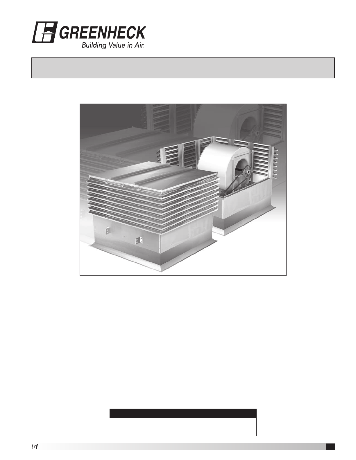
Model LSF Assembly
How to use this manual
Read and save these instructions. This manual is designed to assist with the assembly of Greenheck Model LSF
Louvered Supply Fans. It contains detailed assembly instructions, parts and hardware lists, as well as step-bystep renderings.
Complete descriptions and renderings of all parts and hardware items can be found on pages 2-4. Procedures
described in this manual should be followed in the order they appear.
Receiving and Handling
Upon receiving the equipment, check for both obvious and hidden damage. If damage is found, record all
necessary information on the bill of lading and file a claim with the final carrier. Check to be sure that all parts of
the shipment, including accessories and hardware, are present.
NOTE
Rooftop assembly is recommended. Fan should be
assembled on previously mounted roof curb.
Model LSF Assembly
1
Page 2
®
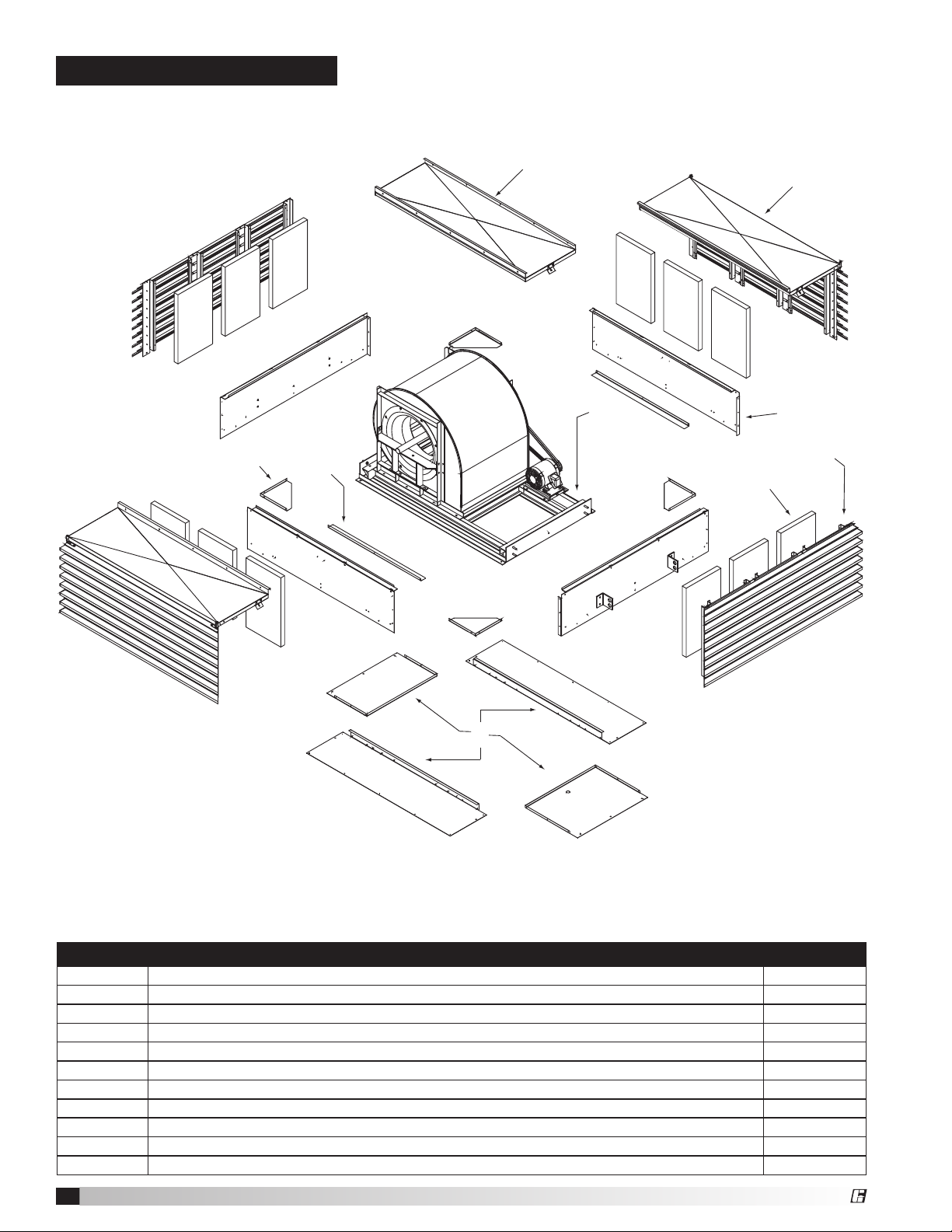
LSF 24, 27 AND 30
6
5
4
1
3
2
7
8
9
PARTS LIST
Item No. Description Quantity
1 Louver Assembly, End 2
2 Louver Assembly, Side 2
3 Base Panel 4
4 Filters See page 12
5 Blower Assembly
6 Curb Adapter Panel (shown upside down) 4
7 Hood Panel, Center 1
8 Reinforcing Angle for Base Panel 2
9 Gusset 4
Hardware Package #821385 See page 4
Model LSF Assembly
2
Page 3
®
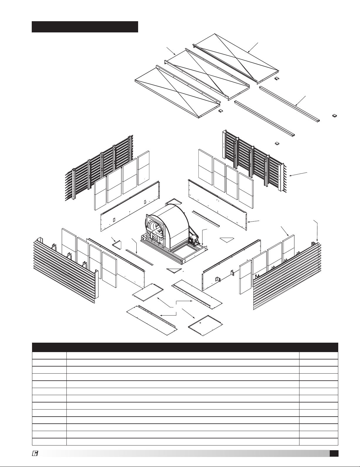
LSF 33 AND 36
6
10
9
5
4
1
3
2
7
8
11
PARTS LIST
Item No. Description Quantity
1 Louver Assembly, End 2
2 Louver Assembly, Side, with Spacer 2
3 Base Panel 4
4 Filters See page 12
5 Blower Assembly
6 Curb Adapter Panel (shown upside down) 4
7 Hood Panel, Center 1
8 Hood Panel, Side 2
9 Reinforcing Angle for Base Panel 2
10 Gusset 4
11 Hood Support Rail 2
Hardware Package #821246 See page 4
Model LSF Assembly
3
Page 4
®
Part
415006 415203 415439 415041
415005 415225 415729 415486 415837
415457 415456 415099 415220 370022
Number
LSF 24 - 30
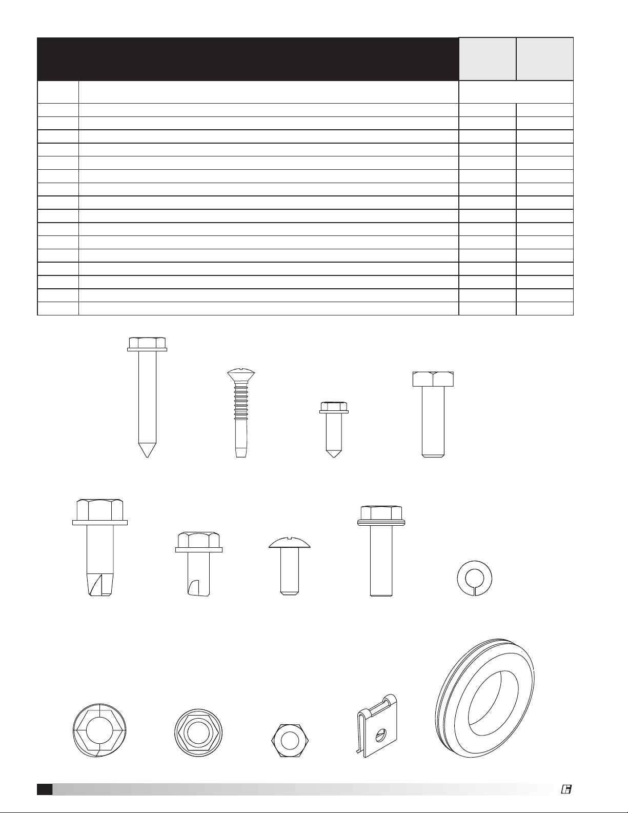
HARDWARE PACKAGE AND FASTENER DETAILS
Hardware
Package
#821385
Item Description Quantity
LSF 33 - 36
Hardware
Package
#821246
415006 Sheet Metal Screw, Indented Hex Washer, Zinc Plated, #14 x 1-1/2 inch 6 6
415203 Sheet Metal Screw, Phillips Oval Head, Stainless Steel, #10 x 1-1/4 inch 96 96
415439 Sheet Metal Screw, Indented Hex Washer, Stainless Steel, #12 x 5/8 inch 70 70
415041 Thread Cutting Screw, Indented Hex Washer Head, Zinc Plated, 5/16 inch - 18 x 1 inch 21 33
415005 Thread Cutting Screw, Indented Hex Washer Head, Zinc Plated, 3/8 inch - 16 x 1 inch 2 2
415225 Thread Cutting Screw, Indented Hex Washer Head, Zinc Plated, 5/16 inch - 18 x 5/8 inch 0 8
415729 Machine Screw, Phillips Truss Head, Stainless Steel, 1/4 inch - 20 x 5/8 inch 10 0
415486 Serrated Flange Fastener (Whiz Lock Screw), Zinc Plated, 5/16 inch - 18 x 1 inch 8 8
415837 Lock Washer, Stainless Steel, 1/4 inch 10 0
415457 Nut, Serrated, Zinc Plated, 3/8 inch - 16 2 2
415456 Nut, Zinc Plated, 5/16 inch - 18 8 8
415099 Nut, Stainless Steel, 1/4 inch - 20 10 0
415220 Tinnerman Clip, 5/16 inch - 18 21 21
370022 Grommet, Neoprene 1 1
450023 Rod, Retainer Pin (not shown) 4 0
506023 Louver Bracket (not shown) 4 0
Note: Depending on unit size, all hardware may not be used. Drawing is not to scale.
Model LSF Assembly
4
Page 5

®
Step 1
Locate and identify parts as listed on Parts List
and Hardware Package and Fastener Details
List on pages 2 and 3. See exploded view for
assistance in identifying parts.
Step 2
Place duct adapter panels upside down so that
the screws can be inserted into the predrilled
holes in the flanges. Fasten the panels together
as shown using the #12 x 5/8 inch stainless sheet
metal screws.
Step 3
Install the neoprene grommet in wiring hole.
Step 4
Flip over the duct adapter panels and apply 3/4 x
3/4 inch gray adhesive-backed foam tape to top
of duct adapter around the edge of the opening
at the proper location; noting the size of the unit.
(The roll of foam tape will be attached to the
blower assembly).
Sizes 24, 27, 30 – flush with edge, all around
Size 33 – flush with edge on long sides, 3/4 inch
away from edge on short sides
Size 36 – flush with edge on long sides, 1-1/4 inch
away on short sides
Step 5
Mount assembled duct adapter onto preexisting
roof curb. Align the adapter squarely on the curb
and nail through the prepunched mounting holes
(nails not provided).
Step 6
Place and align the blower assembly on the duct
adapter—being sure to place the motor near the
wiring hole in the duct adapter. NOTE: Blower
frame will extend 3/4 inch over each end of the
curb. Make sure the frame is centered on the curb.
Step 7
Using the 1/4 inch x 1-1/2 inch lag bolts, fasten
the blower assembly to the curb aligning the
prepunched holes in the blower assembly and
duct adapter.
Step 8
Locate the two (2) wood shipping blocks between
blower assembly frame and isolation base.
Remove and discard the hardware and the blocks.
Step 9
To begin installation of the base panels, remove
the lifting lugs. Save the lifting lugs and mounting
hardware. They will be reused in Step 10.
Model LSF Assembly
5
Page 6

®
Step 10
Set one (1) end panel in place on the end of the
support frame.
Replace the lifting lugs, reusing the hardware
to fasten the panel in place. Do not tighten the
hardware completely until instructed to do so. Use
a 3/8 inch-16x1 inch thread cutting screw in the
center of the end base panel between the lifting
lugs. Do not tighten completely Repeat Step 10 for
the other end base panel.
Step 11
Install reinforcing angle on the two (2) side base
panels. Use #12 x 5/8 inch stainless sheet metal
screws for each reinforcing angle.
Step 12
Place the side base panel with reinforcing angle
on the duct adapter and fasten at both ends using
#12 x 5/8 inch stainless metal screws along both
vertical edges. Repeat Step 12 for the other side
base panel.
Step 13
Install corner gussets on the surface of the duct
adapter and fasten to the bottom corners of the
base panels, using four (4) #12 x 5/8 inch stainless
sheet metal screws in each gusset.
Step 14
Tighten the two (2) bolts in each lifting lug as well
as the one in the center of the base panel that
were not tightened in Step 10.
Model LSF Assembly
6
Page 7

®
Step 15
STOP
Install Tinnerman clips in the slots preprunched at
the top of the base panels.
Step 16
Set one (1) section of the end louver assemblies
(without a cover) in place on an end base panel
(panels with lifting lugs). Fasten posts on louver
assemblies with 5/16 inch-18x1 inch thread
cutting screws, using the prepunched holes in the
posts and Tinnerman clips already installed in the
base panels. Repeat Step 16 for opposite louver
end assembly.
LSF Sizes 24–30 continue on page 8
LSF Sizes 33–36 continue on page 10
Model LSF Assembly
7
Page 8

®
LSF Sizes 24, 27 and 30
Step 17
Set in place one (1) side louver assembly (with
hood panel). Use 5/16 inch -18 x 1 inch thread
cutting screws to fasten posts to base panels as
in Step 16. Using #12 x 5/8 inch stainless sheet
metal screws, fasten the corner posts of the
adjoining sides together at the top and bottom.
Use four (4) screws per louver assembly. Repeat
Step 17 for opposite side louver assembly.
Step 19
Slide the filters into their racks using the diagram
on page 12 as a guide for proper size, location and
orientation of the filters.
Step 18
Fasten mitered louver corners with #10 x 1-1/4 inch
sheet metal screws.
Model LSF Assembly
8
Page 9

®
LSF Sizes 24, 27 and 30
Fasten
Here
Step 20
Set center hood cover on top of louver
assemblies. Slowly close the side hood panels,
one at a time, adjusting the center section
slightly—if necessary—to attain a proper
alignment of all three hood panels.
Step 21
To secure the center hood, locate the center hood
latch. Mark where the slot meets the top louver.
Drill a 9/64 inch hole and insert one (1) sheet metal
screw through center hood latch and top louver.
Repeat Step 21 for opposite side of center hood.
Step 22
Set in place hasp bracket through hood latch.
Hold hasp bracket in place and swing hood panel
open. Mark hasp hole locations on top louver and
drill 1/4 inch holes at each mark. Insert one (1) 1/4
inch - 20 x 1/2 inch machine screw through the
hasp bracket and top louver. Fasten by attaching
one (1) 1/4 inch lock washer and one (1) 1/4 inch
x 20 hex nut to each screw. Follow the same
procedure for the other end of the hood. Repeat
Step 22 for the opposite side hood.
Step 23
Close side hood panels and insert rod retainer pin
through louver bracket to secure side hood panel.
Join side hoods to center hood along hood seams
using four (4) 5/16 inch - 18 x 1 inch serrated
flange fasteners and four (4) 5/16 inch - 18 nuts on
each flange.
Step 24
Using prepunched mounting holes in base panels,
fasten unit to roof curb nailer (fasteners not
provided).
Completed LSF
Size 24, 27 or 30
Model LSF Assembly
9
Page 10

®
LSF Sizes 33 and 36
Step 17
Set in place one (1) side louver assembly with
spacer. Use 5/16 inch -18 x 1 inch thread cutting
screws to fasten posts to base panels as in Step
16. Using #12 x 5/8 inch sheet metal screws,
fasten louver spacer to corner post of end
assembly at the top and bottom. Use four (4)
screws per louver assembly. Repeat Step 17 for
opposite side louver assembly.
Step 19
Slide the filters into their racks using the diagram
on page 12 as a guide for proper size, location and
orientation of the filters.
Step 18
Fasten mitered louver corners with #10 x 1-1/4 inch
sheet metal screws.
Model LSF Assembly
10
Page 11

®
LSF Sizes 33 and 26
Fasten
Here
Step 20
Set in place hood support rails over center posts,
leaving one (1) post between for spacing. Use 5/16
inch - 18 x 5/8 inch thread cutting screws to fasten
hood support rails to center posts; four (4) screws
per center post.
Step 21
Set center hood cover on top of hood support
rails. Align slots in center hood to holes in hood
support rails.
Step 22
Set side hood cover panels on top of unit, one
on each side of center hood. Use thread cutting
screws to fasten hood panels to corner mount
brackets and hood support rails. Join side hoods
to center hood along hood seams using four (4)
5/16 inch - 18 x 1 inch serrated flange fasteners
and four (4) 5/16 inch - 18 nuts on each flange.
Step 23
Using prepunched mounting holes in base panels,
fasten unit to roof curb nailer (fasteners not
provided).
Model LSF Assembly
11
Page 12

®
LSF Filter Sizes and Quantities
All sides are identical.
Size 24 Size 27 Size 30
16 x 20 16 x 20 16 x 20 16 x 20 16 x 25 16 x 20 16 x 25 16 x 25 16 x 25
16 x 20 16 x 20 16 x 20 16 x 20 16 x 25 16 x 20 20 x 25 20 x 25 20 x 25
Size 33 Size 36
20 x 20 20 x 20 20 x 20 20 x 20 20 x 20 20 x 25 20 x 25 20 x 20
20 x 20 20 x 20 20 x 20 20 x 20 25 x 20 25 x 25 25 x 25 25 x 20
Unit Size
Filter
Size
16 x 20
20 x 20
20 x 25
16 x 25
25 x 25
24 27 30 33 36
24 16
32 8
12 16
8 12
8
Warranty
Greenheck warrants this equipment to be free from defects in material and workmanship for a period of one year from
the purchase date. Any units or parts which prove defective during the warranty period will be replaced at our option
when returned to our factory, transportation prepaid. Motors are warranted by the motor manufacturer for a period of
one year. Should motors furnished by Greenheck prove defective during this period, they should be returned to the
nearest authorized motor service station. Greenheck will not be responsible for any removal or installation costs.
As a result of our commitment to continuous improvement, Greenheck reserves the right to change specifications
without notice.
Greenheck Catalog LSF provides additional information
describing the equipment, fan performance, available
accessories, and specification data.
Phone: (715) 359-6171 • Fax: (715) 355-2399 • E-mail: gfcinfo@greenheck.com • Website: www.greenheck.com
458066 • LSF Assembly, Rev. 1, August 1999 Copyright 2008 © Greenheck Fan Corporation
12
AMCA Publication 410-96, Safety Practices for Users and
Installers of Industrial and Commercial Fans, provides
additional safety information. This publication can be
obtained from AMCA International, Inc. at: www.amca.org.
 Loading...