

Page 1
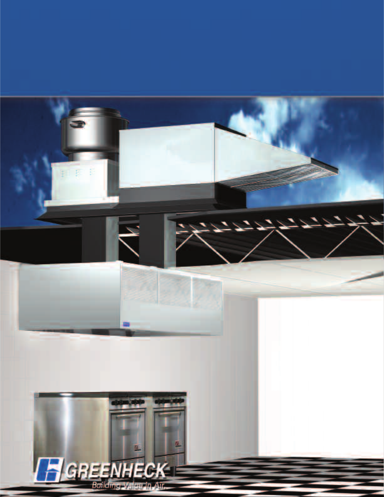
Untempered Make-Up Air
for Kitchen Systems
Models KSFB and KSFD
June
2006
Page 2
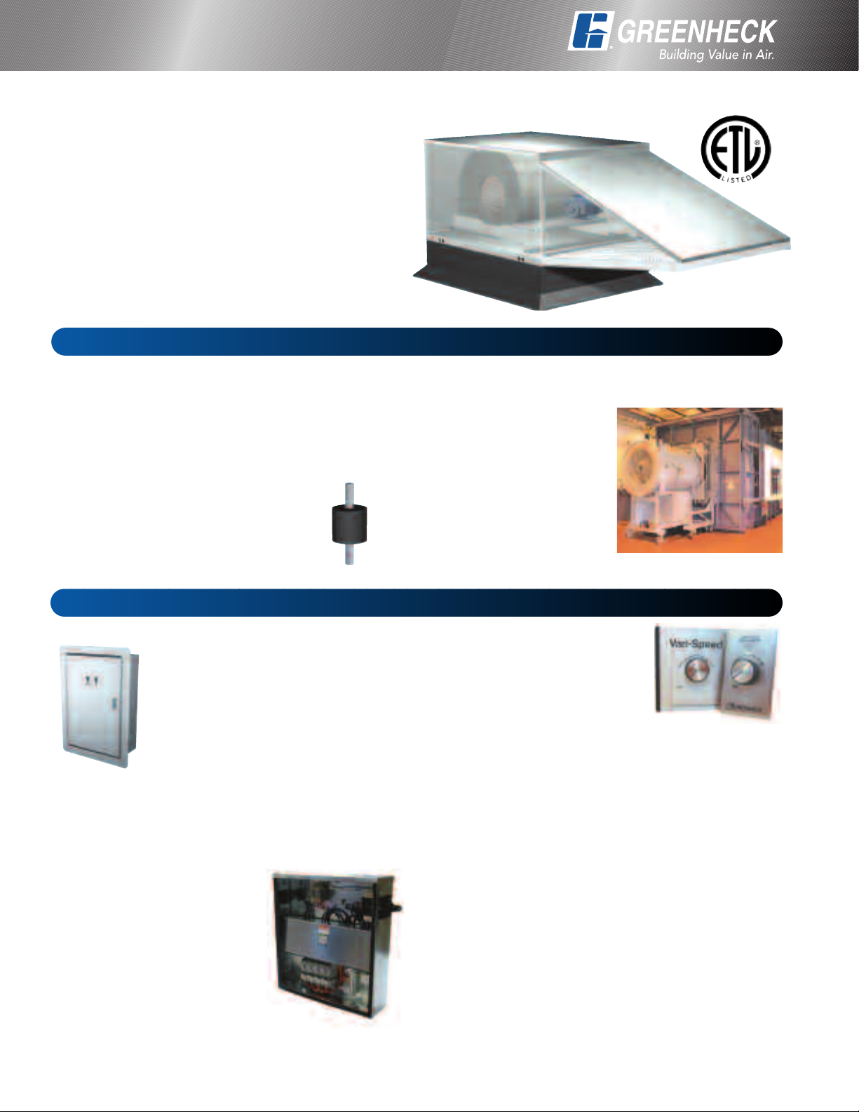
PRODUCT FEATURES
Models KSFB and KSFD
Untempered Make-Up Air Unit
Greenheck’s series KSF is available in a belt drive
(KSFB) and direct drive (KSFD). Both have a compact
design providing untempered make-up air for
commercial and institutional kitchen applications.
Eight available blower sizes provide airflow
capacities up to 10,500 cfm and static pressure
capabilities up to 2.0 in. wg.
Installation may be stand alone or on a combination
curb with exhaust fan. See page 3 for details.
Features
Weatherhood and Filters
A weatherhood is standard and meets NFPA 96
requirements when used with a combination package.
See page 3 for details. All weatherhoods come
standard with UL Class 2 rated, 1 in. washable
aluminum mesh filters.
Vibration Isolators
The motor and wheel assembly is
mounted on vibration isolators to
minimize noise transmission into the
building.
Accessories
Kitchen Fan Control Center (KFCC)
Prewired in compliance to the National
Electrical Code, the KFCC simplifies
field wiring, thereby reducing
installation time and mistakes. The
control center is a UL Listed NEMA 1
panel for mounting indoors. It is
designed to interlock with the fir
suppression system.
Remote Starter Control Panel (RSCP)
The Remote Starter Control Panel (RSCP) offers
safety and reliability for remote operation of up to
four fans. Standard NEMA 3R housing allows panel to
be mounted outdoors.
• Multiple supply voltages
Wide range of horsepowers
•
• Disconnect switch(es)
• Control transformer for low
voltage remote switching
• Terminal strips
• Fuse blocks
•
onic motor overload pr
Electr
otection
e
Reliable Fan Performance
Air performance ratings from Greenheck’s third party
accredited test chamber
ensure accurate data.
Double width, double inlet,
forward curved wheels for
high efficiency and low
sound levels are
constructed of heavy
gauge steel. Wheels are
statically and dynamically
balanced to ensure vibration free operation.
Speed Controller
Available on the KSFD, the
speed controller provides an
economical means of system
balancing.
Roof Curbs
Prefabricated roof curbs are available to reduce
installation time and costs by ensuring compatibility
between the fan and the roof opening. All curbs are
lined with fiberglass insulation to prevent
condensation and reduce sound levels. See
Greenheck’s roof curb catalog for complete details.
Special Coatings
Special coatings ar
protective purposes. Consult your Greenheck
representative or the factory for more information.
e available for decorative or
2
Page 3
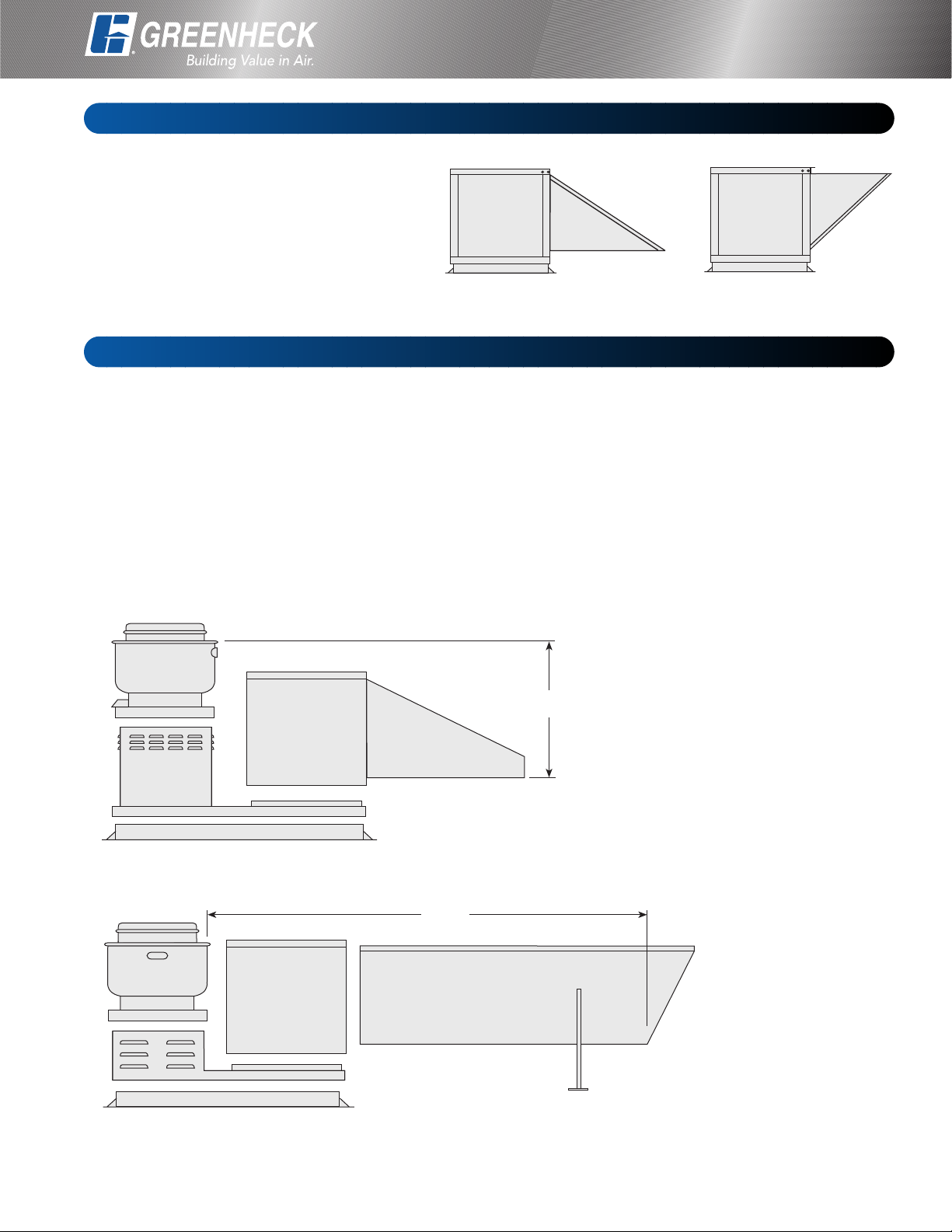
10 ft.
3 ft.
Standard Arrangements
Series KSF has a compact design that is
available in both downblast discharge
(arrangement DB) and horizontal discharge
(arrangement HZ).
Installations may be as stand alone supply
fans as pictured at right or as combination
packages with exhaust and supply fans on a
common curb as shown below.
Combination Packages
INSTALLATION
Arrangement DB Arrangement HZ
With either ten feet of horizontal separation or three
feet of vertical separation, Greenheck has a
combination package for your requirements. The
Greenheck combination package simplifies
installation and reduces field labor costs. This preengineered design offers the benefit of only one roof
penetration for both supply and exhaust ducts, while
ensuring complete compatibility and interface
between the supply fan, exhaust fan, curb and
combination extension.
3 Ft. Vertical Separation - Short Weatherhood
Greenheck combination packages are specifically
designed to comply with NFPA 96, which states:
• Exhaust duct must terminate at least 24 in. above
the roof deck.
• Fan discharge must terminate at least 40 in. above
the roof deck.
• There must be at least 10 ft. of horizontal or 3 ft. of
vertical separation between the intake and exhaust
discharge.
Provides 3 ft. of vertical
separation for
compliance to NFP
A 96.
10 Ft. Horizontal Separation - Extended Weatherhood
Note: Consult local codes and the authority having jurisdiction if ther
questions concer
ning the use of this pr
oduct.
e are
ovides 10 ft. of
Pr
horizontal separation for
compliance to NFPA 96.
3
Page 4

AIR PERFORMANCE
KSFD-70-H05
RPM AMPS Watts
1,600 3.77 405 813 783 776 741 707 671 637 603 527
0.000 0.100 0.125 0.250 0.375 0.500 0.625 0.750 1.000
KSFD-80-H08
RPM AMPS Watts
1,610 8.32 830 1672 1617 1604 1542 1484 1427 1367 1306 1171
0.000 0.100 0.125 0.250 0.375 0.500 0.625 0.750 1.000
KSFD-90-H08
RPM AMPS Watts
1,100 7.8 735 2249 2175 2156 2044 1900 1701 1424 1114
0.000 0.100 0.125 0.250 0.375 0.500 0.625 0.750 1.000
KSFB-109-H15
CFM OV
1,300 1,413
1,600 1,739
1,900 2,065
2,200 2,391
2,575 2,798
RPM 593 678 762 842 987 1118 1236
BHP 0.15 0.19 0.23 0.27 0.35 0.43 0.52
RPM 691 764 833 902 1032 1153 1265 1371 1561
BHP 0.26 0.30 0.35 0.40 0.50 0.60 0.69 0.80 1.02
RPM 793 859 918 976 1091 1201 1303 1404 1588
BHP 0.41 0.47 0.52 0.58 0.70 0.82 0.93 1.04 1.28
RPM 899 956 1011 1061 1161 1261 1356 1448
BHP 0.61 0.68 0.74 0.80 0.94 1.08 1.22 1.35
RPM 1034 1082 1132 1178 1265 1349 1435
BHP 0.95 1.03 1.11 1.18 1.33 1.49 1.65
0.125 0.250 0.375 0.500 0.750 1.000 1.250 1.500 2.000
CFM/Static Pressure in inches of WG
CFM/Static Pressure in inches of WG
CFM/Static Pressure in inches of WG
TOTAL STATIC PRESSURE in inches of WG
KSFB-110-H15
CFM OV
2,400 2,123
2,750 2,433
3,100 2,743
3,450 3,053
3,625
3,207
RPM 741 781 834 885 977 1066 1153 1234 1392
RPM 839 871 913 958 1046 1124 1202 1279 1423
RPM 940 967 996 1036 1118 1192 1262 1330
RPM
RPM 1092 1112 1137 1160 1230
KSFB-112-H15
CFM OV
2,700 1,731
3,300 2,115
3,900
4,500 2,885
5,100 3,269
2,500
RPM
RPM
RPM 691 729 766 804 881 956 1027 1093 1221
RPM 787 817 852 884 951 1017 1082 1146
RPM 884 911 940 970 1027
TOTAL STATIC PRESSURE in inches of WG
0.125 0.250 0.375 0.500 0.750 1.000 1.250 1.500 2.000
BHP 0.54 0.59 0.65 0.72 0.85 0.98 1.12 1.27 1.57
BHP 0.80 0.85 0.91 0.99 1.14 1.29 1.44 1.60 1.93
BHP
BHP 1.55 1.60 1.66 1.73 1.92 2.12
BHP 1.80 1.84 1.91 1.97 2.16
BHP
BHP 0.68 0.77 0.87 0.96 1.15 1.33 1.52 1.72 2.09
BHP 1.09 1.19 1.30 1.41 1.63 1.86 2.08 2.28 2.76
BHP 1.64 1.74 1.87 2.00 2.25 2.51 2.77 3.03
BHP
1.13
1041
0.125 0.250 0.375 0.500 0.750 1.000 1.250 1.500 2.000
507
0.40 0.47 0.55 0.63 0.78 0.94 1.09 1.24
596 641 687 733 821 902 979 1052 1183
2.35
1.18 1.24 1.32 1.50 1.67 1.84 2.01
1064
561
2.47
1089
TOT
617
2.60 2.75 3.03
1119
TIC PRESSURE in inches of WG
A
AL ST
671 768 860 941 1014
1191
1264
Power rating (BHP) does not include drive losses. Performance ratings do not include the effects of appurtenances in the airstream.
4
Page 5

AIR PERFORMANCE
KSFB-115-H25
C
FM OV
4,700 2,146
5,400 2,465
6,100 2,785
6,800 3,105
7,500 3,424
RPM 524 567 608 1.31 722 790 856 915 1031
BHP 1.02 1.16 1.31 1.45 1.74 2.03 2.34 2.63 3.29
RPM 589 628 665 700 768 832 891 950 1056
BHP 1.49 1.66 1.83 1.99 2.32 2.65 2.98 3.33 4.01
RPM 656 691 724 757 819 877 934 988 1090
BHP 2.10 2.29 2.47 2.66 3.04 3.40 3.79 4.16 4.94
RPM 723 755 786 815 872 928 979 1031
BHP 2.86 3.07 3.28 3.48 3.91 4.33 4.72 5.15
RPM 792 821 849 876 929 980
BHP 3.78 4.02 4.25 4.47 4.94 5.41
0.125 0.250 0.375 0.500 0.750 1.000 1.250 1.500 2.000
KSFB-118-H25
CFM OV
6,500 2,145
7,500 2,475
8,500 2,805
9,500 3,135
10,500 3,465
Power rating (BHP) does not include drive losses. Performance ratings do not include the effects of appurtenances in the airstream.
RPM 438 473 510 544 608 667 723 776
BHP 1.26 1.42 1.60 1.78 2.13 2.47 2.83 3.20
RPM 495 526 557 588 646 702 754 802 897
BHP 1.87 2.06 2.26 2.46 2.86 3.27 3.66 4.05 4.92
RPM 554 580 607 636 690 740 790 835 922
BHP 2.66 2.87 3.09 3.32 3.79 4.22 4.69 5.14 6.04
RPM 614 637 661 685 735 783 827 872 954
BHP 3.67 3.86 4.13 4.37 4.90 5.41 5.90 6.43 7.43
RPM 675 695 715 738 783 827 870
BHP 4.91 5.14 5.39 5.66 6.23 6.80 7.37
0.125 0.250 0.375 0.500 0.750 1.000 1.250 1.500 2.000
TOTAL STATIC PRESSURE in inches of WG
TOTAL STATIC PRESSURE in inches of WG
Arrangement HZ - Standard Weatherhood
B
D
A
DIMENSIONAL DATA
STAND ALONE
C
A B C D
Housing 05 183⁄8 315⁄8 20 193⁄8
Housing 08 183⁄8 313⁄4 37 193⁄8
Housing 15 251⁄4 711⁄8 317⁄8 391⁄2
Housing 25 34 813⁄8 401⁄4 473⁄8
All dimensions ar
e in inches
5
Page 6

Extended Weatherhood Option
DIMENSIONAL DATA
STAND ALONE
Arrangement DB - Standard Weatherhood
B
D
A
A B C D
Housing 05 141⁄2 41 20 211⁄4
Housing 08 141⁄2 41 367⁄8 211⁄4
Housing 15 221⁄4 803⁄8 317⁄8 403⁄4
Housing 25 291⁄2 991⁄2 401⁄4 521⁄4
C
All dimensions are in inches
Arrangement DB - Extended Weatherhood
B
D
A
C
A B C D
Housing 05 141⁄2 1711⁄8 20 211⁄4
Housing 08 141⁄2 1653⁄4 367⁄8 211⁄4
Housing 15 221⁄4 1451⁄4 317⁄8 403⁄4
Housing 25 291⁄2 1521⁄2 401⁄4 521⁄4
All dimensions ar
6
e in inches
Page 7

COMBINATION PACKAGE
Arrangement DB3 - Standard Weatherhood
*
Top of
UBE fan
C
op of curb
T
*
B
A
0 in. min.
4
DIMENSIONAL DATA
*
C
6 in. min.
3
Weatherhood
w/Filters
A* B* C*
Housing 05 25 50 701⁄8
Housing 08 353⁄8 527⁄8 821⁄2
Housing 15 427⁄8 55 1313⁄4
Housing 25 583⁄4 661⁄8 1641⁄4
All dimensions are in inches
Arrangement DBC - Extended Weatherhood
A*
Top of
CUBE fan
B*
40 in. min.
Top of curb
* Maximum dimensions
(dependent on CUBE fan)
C*
Adjustable Legs
A* B* C*
Housing 05 25 50 2001⁄4
Housing 08 353⁄8 527⁄8 2071⁄4
Housing 15 427⁄8 55 1965⁄8
Housing 25 583⁄4 661⁄8 2171⁄4
All dimensions are in inches
10 ft. min.
* Maximum dimensions
(dependent on CUBE fan)
7
Page 8

Typical Specifications
General: Make-up air unit shall be as
anufactured by Greenheck or approved equal
m
provided all specifications are met. Greenheck
Model KSFB and KSFD equipment is used as the
basis of design. Performance to be as scheduled
on plans. Make-up air units shall be listed to UL
705. Manufacturer to provide lifting lugs of
adequate strength to allow rigging without
damage.
Unit Casing: Make-up air unit casing shall be
constructed of G-90 galvanized steel. Hinged
panels shall be provided for access to the blower,
motor, and drives. All metal surfaces exposed to
the weather shall be sealed, requiring no caulking
at jobsite.
Fan Section: Centrifugal fans shall be double
width, double inlet. Fan and motor shall be
mounted on a common base and shall be internally
isolated. All blower wheels shall be statically and
dynamically balanced. Ground and polished steel
fan shafts shall be mounted in permanently
lubricated ball bearings. Bearings shall be selected
for a minimum (L10) life in excess of 100,000 hours
at maximum cataloged speeds.
Motors and Drives: Motors shall
e energy efficient, complying
b
with EPACT standards for single
speed ODP and TEFC enclosures.
Motors shall be permanently
lubricated, heavy duty type,
matched to the fan load and
furnished at the specified voltage,
phase and enclosure. The motors
shall be factory wired to a factory
supplied disconnect switch.
Drives shall be sized for a
minimum of 150% of driven
horsepower. Pulleys shall be cast
and have machined surfaces.
Weather Hood: Weather hood
shall be constructed of G90 galvanized steel and
include easily removable 1-inch UL Class 2
aluminum mesh filters. Outdoor air openings shall
be sized so air velocities do not exceed 900 fpm.
Our Warranty
Greenheck warrants this equipment to be free from defects in material and workmanship for a period of one year from the
purchase date. Any units or parts which prove defective during the warranty period will be replaced at our option when returned
to our factory, transportation prepaid. Motors are warranted by the motor manufacturer for a period of one year. Should motors
furnished by Greenheck prove defective during this period, they should be returned to the nearest authorized motor service station.
Greenheck will not be responsible for any removal or installation costs.
esult of our commitment to continuous impro
As a r
vement, Greenheck reserves the right to change specifications without notice.
Greenheck P.O. Box 410 • Schofield, WI 54476-0410 • Phone (715) 359-6171 • greenheck.com
Copyright © 2006 Greenheck Fan Corp. • KSFB KSFD Catalog SN Rev. 2 June 2006
 Loading...