

Page 1
®
®
Part #463556
®
KSFB and KSFD
Installation, Operation and Maintenance Manual
Please read and save these instructions. Read carefully before attempting to assemble, install, operate or maintain the
product described. Protect yourself and others by observing all safety information. Failure to comply with instructions
could result in personal injury and/or property damage! Retain instructions for future reference.
DBC
DB3
General Safety Information
Only qualified personnel should install this unit.
Personnel should have a clear understanding of these
instructions and should be aware of general safety
precautions. Improper installation can result in electric
shock, possible injury due to coming in contact with
moving parts, as well as other potential hazards.
Other considerations may be required if high winds
or seismic activity are present. If more information
is needed, contact a licensed professional engineer
before moving forward.
1. Follow all local electrical and safety codes, as well
as the National Electrical Code (NEC), the National
Fire Protection Agency (NFPA), where applicable.
Follow the Canadian Electric Code (CEC) in
Canada.
DANGER
Always disconnect power before working on or
near a unit. Lock and tag the disconnect switch or
breaker to prevent accidental power up.
CAUTION
When servicing the unit, motor may be hot enough
to cause pain or injury. Allow motor to cool before
servicing.
Horizontal
2. The rotation of the wheel is critical. It must be free
to rotate without striking or rubbing any stationary
objects.
3. Motor must be securely and adequately grounded.
4. Do not spin fan wheel faster than max cataloged
fan rpm. Adjustments to fan speed significantly
effects motor load. If the fan RPM is changed, the
motor current should be checked to make sure it is
not exceeding the motor nameplate amps.
5. Do not allow the power cable to kink or come in
contact with oil, grease, hot surfaces or chemicals.
Replace cord immediately if damaged.
6. Verify that the power source is compatible with the
equipment.
7. Never open blower access doors while the fan is
running.
WARNING!
Impro per installation, adj ustment,
alteration, service or maintenance
can cause property damage, injury or
death. Read the installation, operating
a n d m a i n t e n a n c e i n s t r u c t i o n s
tho r o u g h l y bef o r e install i n g or
servicing this equipment.
KSFB and KSFD Make-Up Air
1
Page 2

®
Receiving
Upon receiving the product check to make sure all
items are accounted for by referencing the bill of
lading to ensure all items were received. Inspect
each crate for shipping damage before accepting
delivery. Notify the carrier if any damage is noticed.
The carrier will make notification on the delivery
receipt acknowledging any damage to the product.
All damage should be noted on all the copies of the
bill of lading which is countersigned by the delivering
carrier. A Carrier Inspection Report should be filled out
by the carrier upon arrival and the Traffic Department.
If damaged upon arrival, file claim with carrier. Any
physical damage to the unit after acceptance is not
the responsibility of Greenheck Fan Corporation.
Unpacking
Verify that all required parts and the correct quantity
of each item have been received. If any items are
missing report shortages to your local representative
to arrange for obtaining missing parts. Sometimes it
is not possible that all items for the unit be shipped
together due to availability of transportation and truck
space. Confirmation of shipment(s) must be limited to
only items on the bill of lading.
Handling
Units are to be rigged and moved by the lifting
brackets provided or by the skid when a forklift is
used. Location of brackets varies by model and size.
Handle in such a manner as to keep from scratching
or chipping the coating. Damaged finish may reduce
ability of unit to resist corrosion.
Storage
Units are protected against damage during shipment.
If the unit cannot be installed and operated
immediately, precautions need to be taken to prevent
deterioration of the unit during storage. The user
assumes responsibility of the unit and accessories
while in storage. The manufacturer will not be
responsible for damage during storage. These
suggestions are provided solely as a convenience to
the user.
INDOOR
The ideal environment for the storage of units and
accessories is indoors, above grade, in a low humidity
atmosphere which is sealed to prevent the entry of
blowing dust, rain, or snow. Temperatures should
be evenly maintained between 30°F (-1°C) and
110°F (43°C) (wide temperature swings may cause
condensation and “sweating” of metal parts). All
accessories must be stored indoors in a clean, dry
atmosphere.
Remove any accumulations of dirt, water, ice or snow
and wipe dry before moving to indoor storage. To
avoid “sweating” of metal parts allow cold parts to
reach room temperature. To dry parts and packages
use a portable electric heater to get rid of any
moisture build up. Leave coverings loose to permit air
circulation and to allow for periodic inspection.
The unit should be stored at least 3½ in. (89 mm) off
the floor on wooden blocks covered with moisture
proof paper or polyethylene sheathing. Aisles between
parts and along all walls should be provided to permit
air circulation and space for inspection.
OUTDOOR
Units designed for outdoor applications may be stored
outdoors, if absolutely necessary. Roads or aisles for
portable cranes and hauling equipment are needed.
The fan should be placed on a level surface to prevent
water from leaking into the unit. The unit should be
elevated on an adequate number of wooden blocks so
that it is above water and snow levels and has enough
blocking to prevent it from settling into soft ground.
Locate parts far enough apart to permit air circulation,
sunlight, and space for periodic inspection. To
minimize water accumulation, place all unit parts on
blocking supports so that rain water will run off.
Do not cover parts with plastic film or tarps as these
cause condensation of moisture from the air passing
through heating and cooling cycles.
Inspection and Maintenance during
Storage
While in storage, inspect fans once per month. Keep a
record of inspection and maintenance performed.
If moisture or dirt accumulations are found on parts,
the source should be located and eliminated. At each
inspection, rotate the fan wheel by hand ten to fifteen
revolutions to distribute lubricant on motor. Every
three months, the fan motor should be energized. If
paint deterioration begins, consideration should be
given to touch-up or repainting. Fans with special
coatings may require special techniques for touch-up
or repair.
Machined parts coated with rust preventive should
be restored to good condition promptly if signs of
rust occur. Immediately remove the original rust
preventive coating with petroleum solvent and clean
with lint-free cloths. Polish any remaining rust from
surface with crocus cloth or fine emery paper and oil.
Do not destroy the continuity of the surfaces. Wipe
clean thoroughly with Tectyl 506 (Ashland Inc.) or
the equivalent. For hard to reach internal surfaces or
for occasional use, consider using Tectyl 511M Rust
Preventive or WD-40 or the equivalent.
KSFB and KSFD Make-Up Air
2
Page 3
®
REMOVING FROM STORAGE
Lifting Area
(4 places)
Supply
Ductwork
by Others
Sealant
Ductwork
As units are removed from storage to be installed
in their final location, they should be protected and
maintained in a similar fashion, until the equipment
goes into operation.
Prior to installing the unit and system components,
inspect the unit assembly to make sure it is in working
order.
1. Check all fasteners, set screws on the fan, wheel,
bearings, drive, motor base and accessories for
tightness.
2. Rotate the fan wheel(s) by hand and assure no
parts are rubbing.
Installation
NOTE
The use of all lifting brackets and a set of spreader
bars is mandatory when lifting unit.
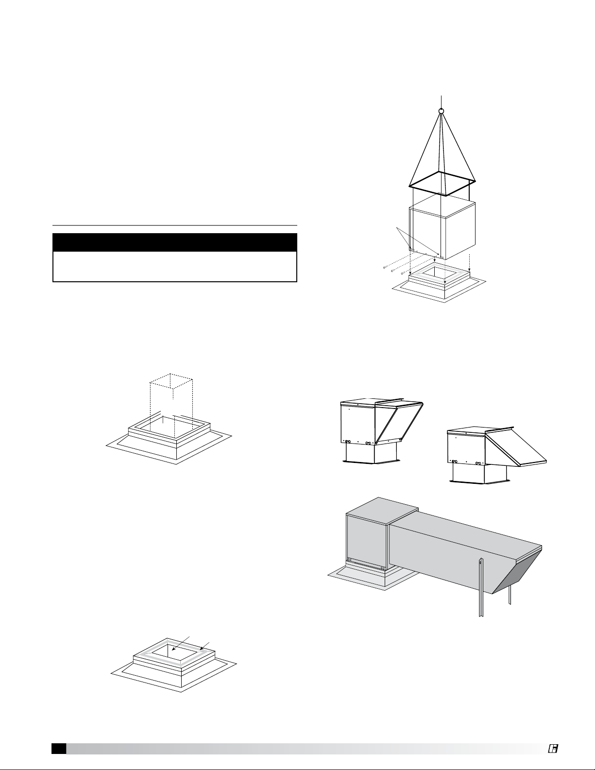
STAND ALONE
1. Install Curb: Position curb on the roof. Refer to
the CAPS submittal for curb location in relation to
the unit. Verify that all unit supports are level, shim
if necessary. Attach curb to roof and flash into
place.
4.
Install Supply Unit: Use a crane and a set of
spreader bars hooked to the factory lifting lugs (as
shown in the diagram) to lift and center the unit on
the curb. Use self-tapping sheet metal screws to
fasten unit to the curb.
5. Assemble Weatherhood: See the reference
section for weatherhood assembly instructions.
Complete Installation
Illustrations show the complete installation of a
standard DB and HZ and extended DB unit.
2. Install Ductwork: Good duct practices should
be followed for all ductwork. All ductwork should
be done in accordance with SMACNA and AMCA
guidelines, NFPA 96 and any local codes.
See the CAPS submittal for the recommended
supply duct sizes. The ductwork should extend far
enough above the roofline to meet the supply unit
once it is installed.
3. Apply Sealant: Before installing supply unit, apply
a sealant around the perimeter of the supply duct
to isolate the fan and minimize vibration.
KSFB and KSFD Make-Up Air
3
Standard Arrangement HZ
Standard Arrangement DB
Extended Arrangement DB
Page 4

®
Supply Duct
Installed
Exhaust Duct Installed
Sealant
Exhaust
Supply
1 in. (25.4 mm)
Inside Flange
COMBO CURB
Supply
Ductwork
by Others
Exhaust
Ductwork
by Others
1. Install Curb: Position curb on the roof. Refer to
the CAPS submittal for curb location in relation to
the unit. Verify that all unit supports are level, shim
if necessary. Attach curb to roof and flash into
place.
2. Install Combination Exension: Install
combination extension over curb, use wood
screws to lag in place. Locate extension so the
tall louvered side is over the exhaust opening, as
shown in illustration.
3. Install Ductwork: Good duct practices should
be followed for all ductwork. All ductwork should
be done in accordance with SMACNA and AMCA
guidelines, NFPA 96 and any local codes.
See the CAPS submittal for the recommended
supply and exhaust duct sizes. The ductwork
should extend far enough above the roofline to
meet the supply and exhaust units once they are
installed.
NOTE
Installing the exhaust fan prior to the supply unit will
allow for easier installation of options.
5. Install Exhaust Fan: Fasten exhaust fan to curb
extension with self-tapping sheet
metal screws.
6. Install Exhaust Options:
Install optional hinge kit with
restraining cables and grease
trap with drain connection.
7.
Install Supply Unit: Use
a crane and a set of
spreader bars hooked
to the factory lifting
lugs (as shown in
the diagram) to lift
and center the unit
on the curb. Use
self-tapping sheet
metal screws to
fasten unit to the
curb.
8. Assembly Weatherhood: See the reference
section for weatherhood assembly instructions.
Complete Installation
Illustrations show the complete installation of a DB3
and DBC unit.
4. Apply Sealant: Before installing exhaust fan and
supply unit, apply a sealant around the perimeter of
the exhaust and supply duct to isolate the fan and
minimize vibration.
KSFB and KSFD Make-Up Air
4
Arrangement DB3
Arrangement DBC
Page 5

®
Electrical Wiring
SUP HP
MCA
EXH HP
MOP
VOLTS HZ PH
Unit’s Total MCA
Voltage, Hertz, Phase
IMPORTANT
Before connecting power to the unit, understand the
following instructions.
All wiring should be done in accordance with the
latest edition of the National Electrical Code ANSI/
NFPA 70 and any local codes that may apply. In
Canada, wiring should be done in accordance with
the Canadian Electrical Code.
alignment is provided in the belt maintenance section).
Check fasteners, set screws and locking collars on
the fan, bearings, drive (KSFB only), motor base and
accessories for tightness.
WARNING
Disconnect and lock-out all power before performing
any maintenance or service to the unit. Failure to do
so could result in property damage and serious
injury or death.
CAUTION
If any of the original wire must be replaced, the
replacement wire must have a temperature rating
of at least 105°C. Any wiring deviations may result
in personal injury or property damage. Greenheck is
not responsible for any damage to or failure of the
unit caused by incorrect final wiring.
DANGER
High voltage electrical input is needed for this
equipment. This work should be performed by a
qualified electrician.
1. Determine the Size of the Main Power Lines:
The unit nameplate states the unit’s voltage and
total amps. The main power lines to the unit should
be sized accordingly.
SPECIAL EQUIPMENT REQUIRED
Required and recommended tools. Equivalent
products may be used.
Voltage &
Amperage
Meter
Manufacturer: Fluke
Model: 177
Phone: 1-800-44-FLUKE
www.fluke.com
Manufacturer: Monarch
Tachometer
Model: Pocket Tach 100
Phone: 1-800-999-3390
www.monarchinstrument.com
1. Check the Voltage: Before starting the unit,
compare the supplied voltage, hertz, and phase
with the unit and motor nameplate information.
2. Check the Blower Rotation: Remove the housing
cover and run the blower momentarily to determine
the rotation. Arrows are placed on the blower scroll
to indicate the proper direction. If the blower is
rotating in the wrong direction, the unit will move
some air, but will not perform as designed. Be sure
to perform a visual inspection to guarantee the
correct blower rotation.
2. Connect the Main Power: Connect the power
line to the disconnect switch. The electrical supply
must be compatible with the fan motor with
regards to voltage, phase, and amperage capacity.
Moreover, the electrical supply line must be
properly fused and conform to local and national
electrical codes. Electrical wires must be located
so as not to rub on moving components.
IMPORTANT
If fan motor is not thermally protected, remote
ov er load pr otection must be in st alled having
th e adequate rating as to voltage, frequency
horsepower, and full load current per phase.
Start-Up — Blower
Pre-Start-Up Check: Rotate the fan wheel by
hand and make sure no parts are rubbing. Check
the V-belt drive (KSFB only) for proper alignment
and tension (a guide for proper belt tension and
KSFB and KSFD Make-Up Air
5
TO REVERSE ROTATION
To reverse the rotation, disconnect and lock-out the
power.
Single Phase: Rewire the motor per the
manufacturer’s instructions.
Three Phase: Interchange any two power leads.
3. Check for Vibration: Check for unusual noise,
vibration or overheating of the bearings and take
corrective action.
Excessive vibration may be experienced during
the initial start-up. Left unchecked, it can cause a
multitude of problems, including structural and/or
component failure.
Generally, fan vibration and noise is transmitted
to other parts of the building by the ductwork. To
minimize this undesirable effect, the use of heavy
canvas connectors is recommended.
4. Motor Check: Measure the motor’s voltage, amps
and RPM. Compare to the specifications. Motor
amps can be reduced by lowering the motor RPM
or increasing system static pressure.
Page 6

®
5. Air Volume Measurement and Check: Measure
Deflection =
Belt Span
64
Belt Span
MOTOR
FAN
MOTOR
the unit’s air volume (cfm) and compare it with its
rated air volume. If the air volume is off, adjust the
belts and drives (KSFB) or speed controller (KSFD)
until the specified air volume is reached.
The most accurate method for measuring the air
volume is a pitot traverse method downstream of
the blower. Other methods can be used, but should
be proven and accurate.
WARNING
Changing the belts or drives can significantl y
increase the amp draw of the motor. If changes
are made to the drives or belts, the amps must be
checked to assure no over-amping.
Maintenance
WARNING
Disconnect and lock-out all power before performing
any maintenance or service to the unit. Failure to do
so could result in property damage and serious
injury or death.
changing or cleaning more or less often.
Aluminum mesh filters can be washed in warm soapy
water. An adhesive spray can be added to increase
the filter efficiency.
• Be sure to reinstall filters with the airflow in the
correct direction. An airflow direction arrow is
located on the side of the filters.
• Replacement filters should be from the same
manufacturer and be the same size as the original
filters provided with the unit.
Motors – Motor maintenance is generally limited to
cleaning and lubrication (where applicable).
Cleaning should be limited to exterior surfaces only.
Removing dust and grease build-up on the motor
assures proper motor cooling.
Motors supplied with grease fittings should be
greased in accordance with the manufacturer’s
recommendations.
• Greasing of motors is only intended when fittings
are provided. Many fractional horsepower motors
are permanently lubricated and will not require
additional lubrication.
V-Belt Drives (KSFB only) – V-belt drives
must be checked on a regular basis for wear, tension,
alignment and dirt accumulation. Check the alignment
by using a straight edge across both sheaves and
the tension by measuring the deflection in the belt as
shown.
• Improper belt tension and/or misaligned sheaves
lead to premature and frequent belt failures.
• Do not pry belts on or off the sheave. Loosen belt
tension until belts can be removed by gently lifting
them off of the sheaves.
• When replacing V-belts on multiple groove drives,
all belts should be changed to provide uniform
drive loading.
• Do not install new belts on worn sheaves. If the
sheaves have grooves worn in them, they must be
replaced before new belts are installed.
Wheels – Wheels require little attention when
moving clean air. Occasionally, oil and dust may
accumulate on the wheel causing imbalance. When
this occurs the wheel and housing should be cleaned
to assure proper operation.
Filters – Filter maintenance is generally limited
to cleaning and replacement. The filters in the unit
should be inspected at least every three (3) months.
Depending on the environment, filters could require
CAUTION
Do not allow water or solvents to enter the motor or
bearings. Under no circumstances should motors or
bearings be sprayed with steam, water or solvents.
Maintenance Details
Unit Model Number _______________________________
(e.g. KFSB-115-H25)
Unit Serial Number _______________________________
(e.g. 04C99999 or 10111000)
Start-Up Date _______________________________
Start-Up Personnel Name __________________________
Start-Up Company _______________________________
Phone Number _______________________________
Pre Start-Up Checklist – check boxes as items
are completed.
oCheck tightness of all factory wiring connections
oHand-rotate blower to verify free rotation
oVerify supply voltage to the main disconnect
Start-Up Blower Checklist – refer to IOM for
further detail.
oCheck line voltage L1-L2 __________
L2-L3 __________
L1-L3 __________
oCheck blower rotation
oCheck for vibration
oSupply fan RPM _________ RPM
oMotor nameplate amps _________ Amps
oActual motor amps _________ Amps
oActual CFM delivered _________ CFM
KSFB and KSFD Make-Up Air
6
Page 7

®
Reference
Standard HZ and DB3 Weatherhood
Assembly Instructions
Housing 05 HZ Housing 05 DB3
6. Insert the factory provided aluminum mesh intake
filter(s) into the track located in the face of the
weatherhood. Filters slide in from the top. Be
sure the filters are properly orientated (an airflow
direction arrow is located on the side of the filters).
Track for aluminum
mesh intake filters.
TOOLS REQUIRED
• 5/16 inch nut runner
• Caulk gun with weatherproof sealant
The KSFB/D Standard HZ and DB3 weatherhoods are
folded up and shipped on top of
the unit.
To install:
1. Rotate one side up on
weatherhood.
a. Run one (1) sheet metal
screw where shown to
hold side in rotated position.
b. Rotate opposite side up on weatherhood and
repeat step 1A.
2. Rotate assembly forward.
3. Screw the sides of the weatherhood to the unit.
Pilot holes are provided.
Housing 05 HZ
Center filter track
(2 pieces)
Slot in unit
Housing 05, 08, 15 & 25 HZ
Extended 10 ft. DBC Weatherhood
Assembly Instructions
Housing 05 & 08
Rotate sides up, install screws.
Rotate assembly forward. See Step 3.
The KSFB/D extended 10 ft. weatherhood is made up
Housing 15 & 25
of up to three parts: 1) a fixed section attached to the
4. Caulk all seams with an appropriate weatherproof
sealant.
5. There are four housing sizes: H05, H08, H15, and
H25.
• The H05 housing requires a single filter at the
face of the intake hood.
• The H08, H15, and H25 housings require multiple
filters installed at the face of the intake hood.
As such, these three units require installation of an
additional center track (two pieces) to support the
multiple filters. The filters and center track pieces
are shipped inside the KSFB/D housing. Slide
the tabbed end of each track into the slot at the
bottom of the intake opening on the unit housing.
Rotate the tracks up to the top outer edge of the
weatherhood such that the weatherhood edge
slides into the slot in the tracks.
unit, 2) a folded up section shipped on top of the fixed
section, and 3) an assembled section shipped on top
of the fixed section. This three part assembly applies
to both the DB and HZ arrangements.
To install:
1. Lift unit onto curb. Prior to disconnecting from
crane, adjust support legs on fixed section of the
extended weatherhood to appropriate height to
support hood.
2. For housing sizes H05 and H08, rotate the
assembled section of the weatherhood forward.
3. For housing sizes H15 and H25, rotate one side up
on the weatherhood.
a) Run one (1) sheet metal screw where shown to
hold side in rotated position.
b) Rotate opposite side up on weatherhood and
repeat step 3A.
KSFB and KSFD Make-Up Air
7
Page 8

Rotate sides up, install screws.
®
Rotate assembly forward. See Step 3.
4. Screw the sides (and bottom on Housing 05 & 08)
of the weatherhood to the unit. Pilot holes are
provided.
5. Caulk all seams with an appropriate weatherproof
sealant.
6. There are four housing sizes: H05, H08, H15, and
H25. The H05 housing requires a single filter at
the face of the intake hood. The H08, H15, and
H25 housings require multiple filters installed at
the face of the intake hood. As such, these three
units require installation of an additional center
track (two pieces) to support the multiple filters.
Center filter track
(2 pieces)
The filters and center track pieces are shipped
inside the KSFB/D housing. Slide the tabbed
end of each track into the slot at the bottom of
the intake opening. Rotate the tracks up to the
top outer edge of the weatherhood such that
the weatherhood edge slides into the slot in the
tracks.
7. Insert the factory provided 1-inch aluminum mesh
intake filter(s) into the track located in the face of
the weatherhood. Filters slide in from the top. Be
sure the filters are properly orientated (an airflow
direction arrow is located on the side of the filters).
NOTE: Housing 15 & 25 have no bottom section to
the weatherhood.
Slot in unit
Warranty
Greenheck warrants this equipment to be free from defects in material and workmanship for a period of one year from
the purchase date. Any units or parts which prove defective during the warranty period will be replaced at our option
when returned to our factory, transportation prepaid. Motors are warranted by the motor manufacturer for a period of
one year. Should motors furnished by Greenheck prove defective during this period, they should be returned to the
nearest authorized motor service station. Greenheck will not be responsible for any removal or installation costs.
As a result of our commitment to continuous improvement, Greenheck reserves the right to change specifications
without notice.
Greenheck Catalog Model KSFB and KSFD provides additional information
describing the equipment, fan performance, available accessories,
AMCA Publication 410-96, Safety Practices for Users and Installers of
Industrial and Commercial Fans, provides additional safety information.
This publication can be obtained from AMCA International, Inc. at:
Phone: (715) 359-6171 • Fax: (715) 355-2399 • E-mail: gfcinfo@greenheck.com • Website: www.greenheck.com
and specification data.
www.amca.org.
Contact Greenheck Fan Corporation:
463556 • KSFB and KSFD, Rev. 3, February 2008 Copyright 2008 © Greenheck Fan Corporation
8
 Loading...