

Page 1
Document 475730
Kitchen Fan Control Center
®
Installation, Operation and Maintenance Manual
Please read and save these instructions for future reference. Read carefully before attempting to assemble,
install, operate or maintain the product described. Protect yourself and others by observing all safety
information. Failure to comply with instructions could result in personal injury and/or property damage!
WARNING
Electrical shock hazard. Can cause equipment
damage, personal injury, or death. Service must be
performed only by personnel that are knowledgeable
in the operation of the equipment being controlled.
CAUTION
It is the responsibility of the installer to make sure
both electrical and gas appliances shut down in
the event of a fire or in the event of a power loss to
the building when this sequence is required by the
authority having jurisdiction.
Table of Contents
General Description ..........................2
Receiving and Handling .......................2
Installation
Control Box .................................3
Switch Mounting .............................3
Resistive Temperature Detector(s)
Hood Mounting .............................3
Duct Collar Mounting ........................4
Thermostat
Hood Mounting .............................4
Duct Collar Mounting ........................5
Electrical Connections
Power for KFCC .............................6
Power for Hood Lights ........................6
Power for Starters and Fans ....................6
Fire System Integration ........................7
Spare Fire Relay .............................7
Switches
Fan, 1-Speed ..............................7
Fan, 2-Speed ..............................7
Lights ....................................7
Tempered Supply, Heat Only ..................8
Cool Only ..................8
Heat and Cool ...............8
Combination Fan/Light Switch .................8
Auto-Damper Switch on KFCC ................8
Make-Up Air Interface .......................8
Power for Shunt Trip .........................8
Audible Alarm ..............................8
Lights Out in Fire ...........................9
Extra Fire Relay .............................9
Extra Exhaust Relay .........................9
Extra Supply Relay .........................10
Exhaust Fan Failure Indicator .................10
Supply Fan Failure Indicator ..................10
Status Lights ..............................10
Water Wash Control Panel Interface ...........10
Temperature Interlock, Digital .................11
Temperature Interlock, Thermostat .............11
Digital Temperature Interlock Configuration . . 12-13
Thermostat Style Temperature
Interlock Configuration ......................13
KFCC Field Connection Checklist ..............14
General Wiring Diagram ......................15
Testing ....................................16
Operation ..................................17
Troubleshooting .............................17
Maintenance ...............................18
Frequently Asked Questions ..................18
Replacement Parts ..........................19
Codes and Standards ........................19
Our Commitment ............................20
®
Kitchen Fan Control Center
1
Page 2
General Description
Receiving and Handling
Description
The kitchen fan control center, or KFCC, is a
pre-engineered package designed to control the
operation of fans in a constant-volume kitchen. The
package consists of a cabinet encasing one or more fan
motor starters interlocked together for on/off operation.
Different fan, light and thermal switch combinations may
be provided to operate the kitchen hood fan(s), light(s),
and heating/cooling capabilities of the supply air. The
control center as a standard is equipped with additional
relays prewired to the fan starter(s). These additional
relays are capable of turning on the kitchen exhaust and
shutting down supply regardless of the present state of
the fans via integration of a fire system microswitch with
factory terminals. The control center can be equipped
with temperature interlock, designed to automatically
start kitchen fans and keep them running while heat is
being generated from the cooking appliances. Hood
systems should always be manually started before the
cooking equipment is turned on, but if forgotten the
interlock will safely trigger the fans to start once heat is
detected. Other options are available.
Purpose
The purpose of the KFCC is to provide a complete
control center to provide and house all fan starters. The
control center provides a common connection point
to interlock kitchen exhaust, supply, and hood lights
with the hood’s fire suppression system. The cabinet
is pre-engineered with terminal blocks for most field
wiring connections. The control center can also be
equipped with interlock between the exhaust fans and
cooking equipment, as to meet International Mechanical
Code (IMC) 2006 section 507.2.1.1. In this case, the
system will utilize a temperature sensor in the exhaust
duct collar or capture area in the hood to detect heat
generated from cooking operations and automatically
activate the exhaust fans if not already running.
Product Application
The KFCC is designed for both Type I and Type II
(grease and non-grease) constant-volume hood
systems, where starters are needed to activate fans.
The control center can operate both single and three
phase fans. Greenheck recommends using one KFCC
per hood system (activates all fans simultaneously).
When temperature interlock is provided in this package,
it is not to be used in conjunction with exhaust fire
dampers.
Receiving
Upon receiving the product, check to make sure all
items are accounted for by referencing the bill of lading
to ensure all items were received. Notify the carrier if
any damage is noticed. The carrier will make notification
on the delivery receipt acknowledging any damage to
the product. All damage should be noted on all of the
copies of the bill of lading which is countersigned by the
delivering carrier. If damaged upon arrival, file a claim
with the carrier. Any physical damage to the unit after
acceptance is not the responsibility of the manufacturer.
Unpacking
Verify that all required parts and the correct quantity of
each item have been received. If any items are missing,
report shortages to your local representative to arrange
for obtaining missing parts.
Storage
If a kitchen fan control center must be stored prior to
installation, it must be protected from dirt and moisture.
Indoor storage is highly recommended. For outdoor
storage, cover the control package with a tarp to keep it
clean, dry, and protected from UV (ultraviolet) radiation
damage.
NOTE
Improper storage which results in damage to the unit
will void the warranty.
Handling
Make sure the equipment does not suffer any heavy
vibration or knocks.
Kitchen Fan Control Center
2
®
Page 3
Installation
0.75 to 0.875 inch
(19.0 to 22.2 mm)
diameter hole
Hood Surface
3 inch air space
19.525 inches
Sensor Install
(cutout area)
Exhaust Area
Supply Area
(optional)
P.O.BOX 410 SCHOFIELD,
TITLE
INSTR, ADJ.
J-Box Plate
PN 732396
Temperature Sensor (RTD)
PN 384925
Octagon Cover
PN 380926
TENSION RING, AND PLACE OVER HOLE.
E THE COMPRESSION SEAL AND PLACE
NOTE
All field installation of electrical equipment must be
done to meet all NEC and electrical codes.
Control Box Mounting
NOTE
Control box may be factory mounted. If so, continue
to the next section.
Locate an area with enough space to mount the control
box and securely fasten to the wall. Use appropriate
type fasteners depending on the mounting location.
Avoid installing the control box in environments with
high magnetic and/or radio frequency interference.
Switch Mounting
NOTE
If the switches were NOT shipped loose, provided in a
separate junction box, continue to the next section.
Resistive Temperature Detector(s)
- Hood Mounting
NOTE
The resistive temperature detector(s), or RTD(s), will
be provided only if the digital temperature interlock
option was configured/ordered with the unit. If it
wasn’t, continue to the next section.
Resistive temperature detector(s) may be factory
installed. If so, continue to the next section.
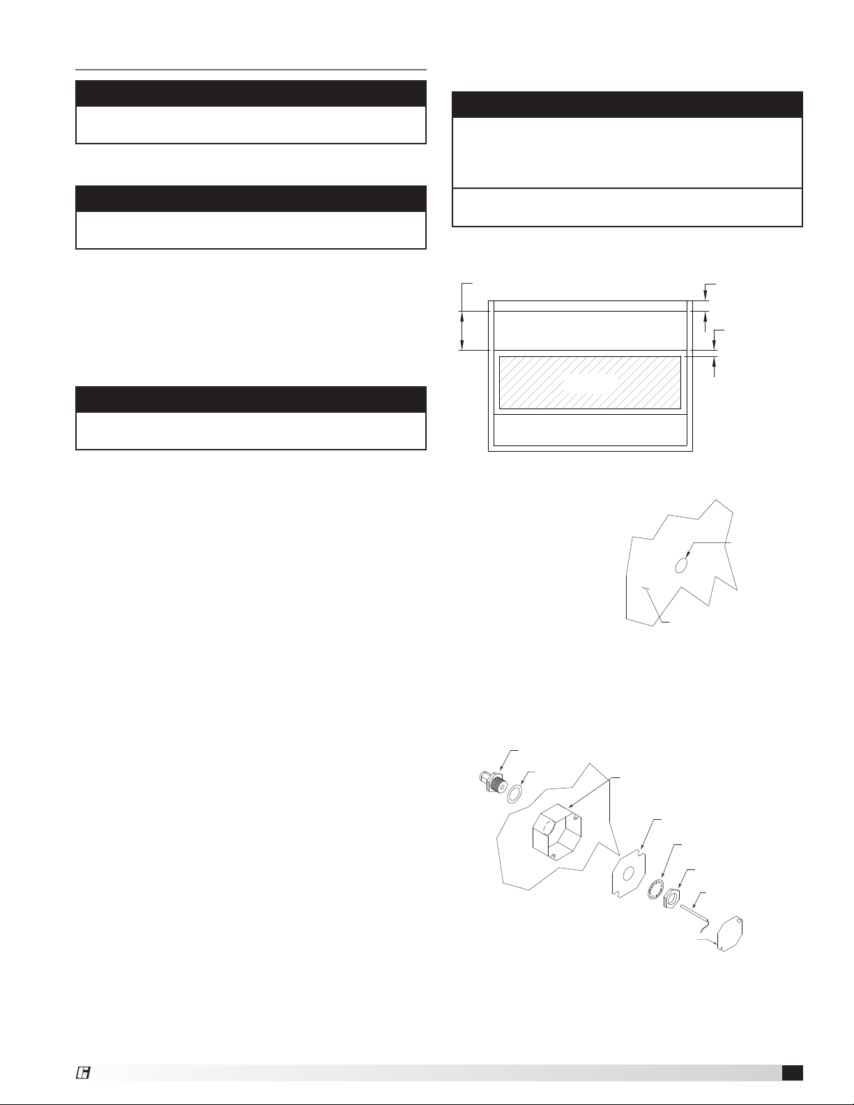
1. Locate flat area(s) at the top interior of the hood in
front of the filters, towards the front of the hood.
2 inch typical
Locate an area with enough space to mount the
switches junction box and fasten to the wall.
Top View of Exhaust Hood
2. Cut a 3/4 to 7/8-inch
(19.0 to 22.2 mm) diameter hole
in the flat spot of the capture
tank. Make sure the
resistive temperature
detector(s) will not
interfere with fire
system nozzles and is
not within 12inches of
light fixtures.
3. Place the J-box plate inside of the octagon extension
ring and place over the hole.
4. Disassemble the compression seal and place through
hole and J-box plate as shown. Tighten the nut inside
the octagon extension ring.
1/4-inch Compression Seal
PN 463570
Gasket
Octagon Extension
PN 830125
Lock Washer
Nut
®
5. Place the resistive temperature detector through the
compression seal and tighten the compression fitting.
6. Refer to Electrical Connections section for
instructions on wiring the temperature sensor.
7. Install the cover for the octagon box.
Kitchen Fan Control Center
3
Page 4
Resistive Temperature Detector(s)
19.525 inches
3 inch air space
2 inch typical
Exhaust Area
Supply Area
(optional)
Sensor Install
(cut out area)
- Duct Collar Mounting
NOTE
The resistive temperature detector(s), or RTD(s), will
be provided only if the digital temperature interlock
option was configured/ordered with the unit. If it
wasn’t, continue to the next section.
Resistive temperature detector(s) may be factory
installed. If so, continue to the next section.
1. Locate the exhaust duct on top of the hood. A 3/4
to 7/8-inch
be cut into the duct 2inches (50.8 mm) above the
hood top. Center the hole along the side of the duct.
Make sure that the resistive temperature detector will
not interfere with any fire system nozzles, or other
items installed in the exhaust duct. If an exhaust fire
damper is present the hood exhaust collar, it must be
removed prior to temperature sensor installation.
2. Place the J-box plate inside of the octagon extension
ring and place over the hole in the exhaust collar.
3. Disassemble the compression seal and place through
hole in duct collar and J-box plate as shown. Tighten
the nut inside the octagon extension ring.
4. Place the resistive temperature detector through the
compression seal and tighten the compression fitting.
5. Refer to Electrical Connections section for
instructions on wiring the temperature sensor.
6. Install the cover for the octagon box.
Kitchen Fan Control Center
4
(19.0 to 22.2 mm) diameter hole must
0.75 to 0.875 inch
(19.0 to 22.2 mm)
diameter hole
1/4-inch Compression Seal
PN 463570
Gasket
Hood Exhaust Collar
Front Side
Octagon Extension
PN 830125
Octagon Cover
PN 380926
2 inches
(50.8 mm)
J-Box Plate
PN 732396
Lock Washer
Nut
Temperature Sensor (RTD)
PN 384925
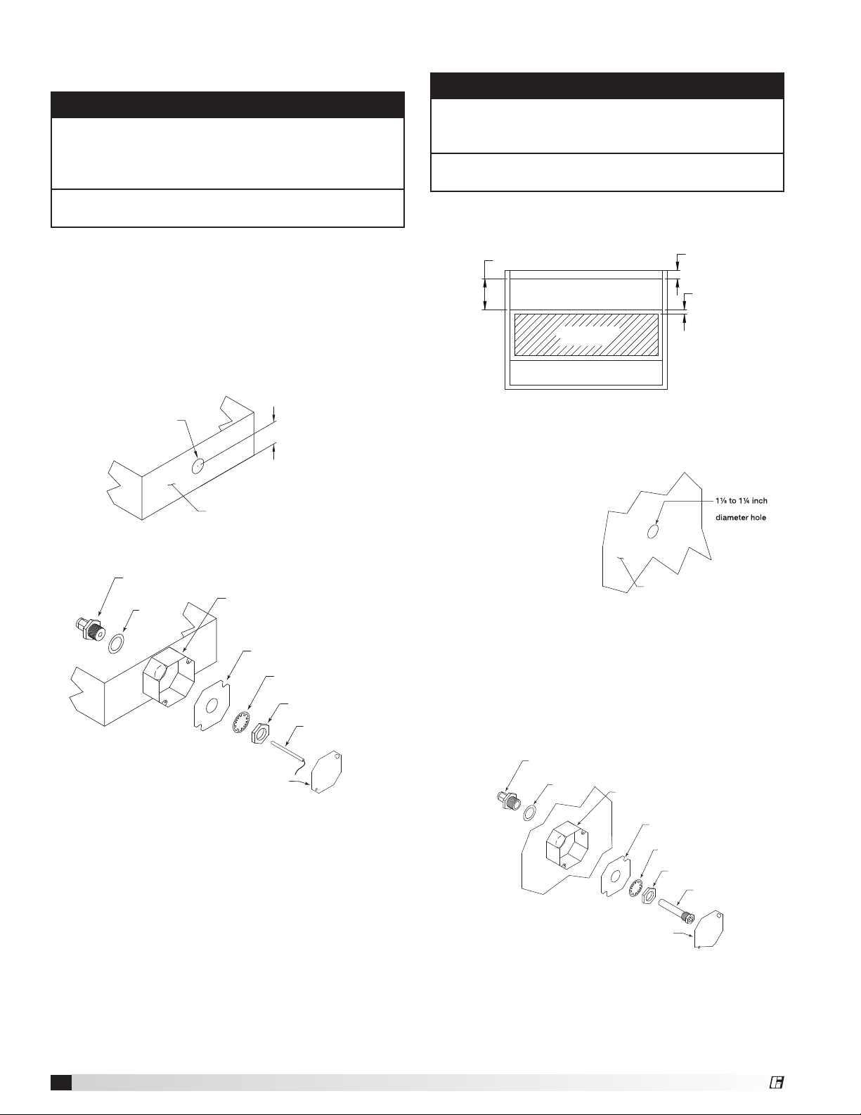
Thermostat - Hood Mounting
NOTE
The thermostat will be provided only if the thermostat
style temperature interlock option was configured/ordered
with the unit. If it wasn’t, continue to the next section.
The thermostat may be factory installed. If so,
continue to the next section.
Recommended thermostat mounting location is in the
Nut
(20.32cm)
(28.58 to 31.75 mm)
Thermostat
PN 383923
flat interior of the hood and at least 8 inches
from light fixture.
Hood Plan View
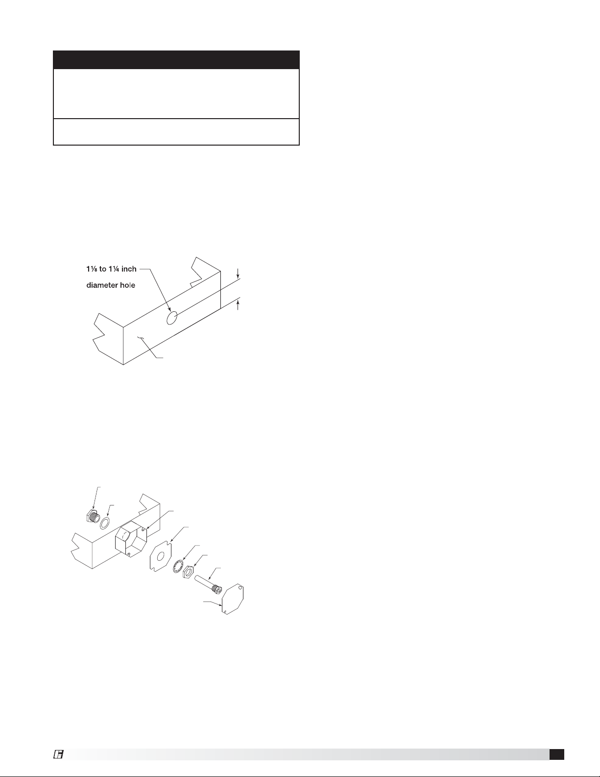
1. Locate the flat area(s) at the top interior of the hood in
front of the filters, towards the front of the hood. A 11⁄8
to 1¼ inch (28.58 to 31.75 mm) diameter hole must
be cut into the top of
the capture tank. Make
sure the thermostat
will not interfere with
the fire system nozzles
and is not within eight
inches
the light fixtures.
(20.32cm) of
Hood Surface
2. Place the J-box plate inside of the octagon extension
ring and place over the hole.
3. Insert the Evergreen compression seal fitting into the
hole from the inside the hood, making sure the gasket
is placed on the fitting before inserting it into the
hole. Install the J-box plate, lock washer, and 1-1/2
inch (38 mm) nut over the threaded portion of the
compression seal fitting and tighten securely.
5/8-inch Compression Seal
PN 452614
Gasket
Octagon Extension
PN 830125
J-Box Plate
PN 732396
Lock Washer
Octagon Cover
PN 380926
4. Place the thermostat detector through the
compression seal and tighten the compression fitting
to 35 ft-lbs.
5. Refer to Electrical Connections section for
instructions on wiring the thermostat.
6. Install the cover for the octagon box.
®
Page 5
Thermostat - Duct Collar Mounting
NOTE
The thermostat will be provided only if the thermostat
style temperature interlock option was configured/
ordered with the unit. If it wasn’t, continue to the next
section.
The thermostat may be factory installed. If so,
continue to the next section.
1. Locate the exhaust duct on top of the hood. A 11⁄8to
1¼-inch (28.58 to 31.75 mm) diameter hole must be
cut into the duct 2inches (50.8 mm) above the hood
top. Center the hole along the side of the duct. Make
sure that the thermostat will not interfere with any fire
system nozzles, or other items installed in the exhaust
duct. If an exhaust fire damper is present the hood
exhaust collar, it must be removed prior to thermostat
installation.
(28.58 to 31.75 mm)
Hood Exhaust Collar
(front side)
2 inches
(50.8 mm)
2. Place the J-box plate inside of the octagon extension
ring and place over the hole.
3. Insert the Evergreen Quik-Seal fitting into the hole
from the inside of the duct, making sure the gasket is
placed on the fitting before inserting it into the hole.
Install the J-box plate, lock washer, and 1-1/2 inch
(38 mm) nut on the threaded portion of the Evergreen
Quik-Seal fitting and tighten securely.
1/2 inch Quik-Seal
PN 451168
Gasket
Octagon Extension
PN 830125
J-Box Plate
PN 732396
Lock Washer
Nut
Thermostat
PN 383923
Octagon Cover
PN 380926
4. Thread the thermostat through the Quick-Seal and
tighten to 35 ft-lbs.
5. Refer to Electrical Connections section for
instructions on wiring the thermostat.
6. Install the cover for the octagon box.
®
Kitchen Fan Control Center
5
Page 6
Electrical Connections
NOTE
All field wiring of electrical equipment must be done to
meet all NEC and electrical codes.
The extent of field wiring required will depend on the
options and general configuration of the KFCC. Each
option is broken out in the next portion of this manual.
Each option will either be factory wired or will require
field wiring. Use 14 AWG, 60°C copper wire unless
otherwise specified.
Power for KFCC
The KFCC needs a power source to operate all inner
components. This power source cannot be on a shunt
trip breaker; the power must remain constant to the
panel, even in the event of a kitchen fire.
Power for KFCC
• 120 VAC, 15 amp circuit to terminals H1 and N1
L1
H1
CONTROL INPUT:
120 VAC, 15 AMPS FROM BREAKER
Power for Hood Lights (Optional)
If the KFCC is configured for hood light control, a
separate power source for each light circuit will need
to be run to the panel as well to power the lights. The
KFCC can provide up to three light circuits.
Power for Hood Lights
• 120 VAC, 15 amp circuit to terminals H2 and N2
(first light circuit)
• 120 VAC, 15 amp circuit to terminals H3 and N3
(second light circuit)
• 120 VAC, 15 amp circuit to terminals H4 and N4
(third light circuit)
Hood Lights
• To terminals B2 and W2 (first light circuit)
• To terminals B3 and W3 (second light circuit)
• To terminals B4 and W4 (third light circuit)
L1
H2
BK
LIGHT INPUT: 120 VAC,
15 AMPS FROM BREAKER
S-1
B2
LT
1400W max.
LT
N1
G
N
N
WH
W2
N2
Power for Starters and Fans
The KFCC is equipped with contactors that may have
thermal overloads attached to them. Each fan should
have a designated power source. The breaker size
(amps), wire gauge, phase, and voltage for each fan is
specified on the KFCC wiring diagram. Two speed fans
will require two separate starters.
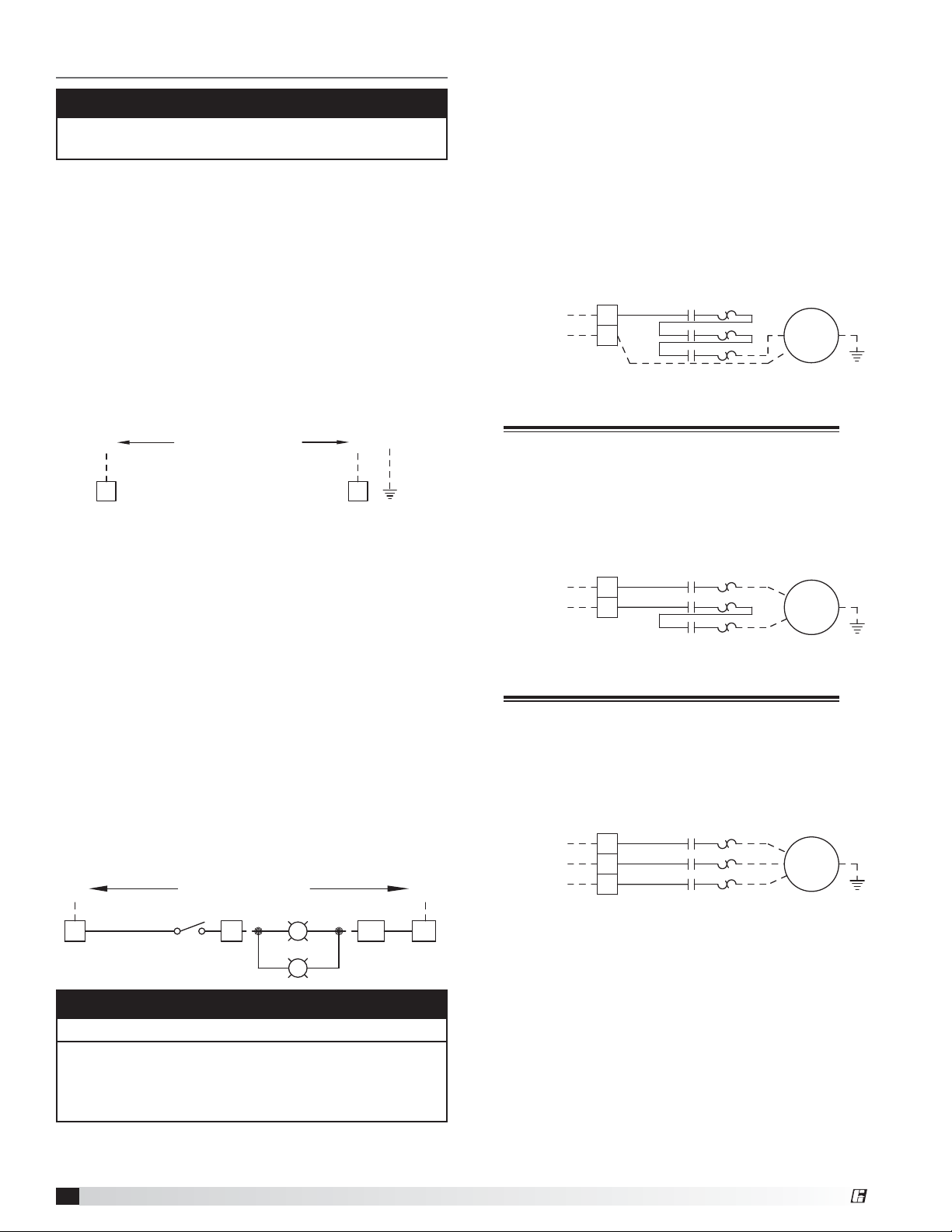
115 VAC Single Phase Fan(s) Power Wiring
• LINE - from breaker to terminals L1 and L2
• LOAD, 115 VAC - from terminal block L1 and T3 on
the bottom of contactor/overload to fan disconnect
OL1 ST1
T1
T2
T3
T1
T2
T3
T1
T2
T3
T1
T2
T3
OL2 ST2
T1
T2
T3
OL3 ST3
T1
T2
T3
Exh
FAN 1
Exh
FAN 2
Exh
FAN 3
INPUT POWER
2 wire
115/1 phase
from breaker
L1
N
L2
Single phase, 115 VAC
Wiring Connection Example
L1
L2
L3
200/208/230/277 VAC Single Phase Fan(s) Power
Wiring
• LINE - from breaker to terminals L1 and L2
• LOAD, 200/208/230/277 VAC - from T1 and T3 on
the bottom of contactor/overload to fan disconnect
INPUT POWER
2 wire
208/1 phase
from breaker
L1
L2
Single phase, 200/208/230/277 VAC
Wiring Connection Example
L1
L2
L3
Three Phase Fan(s) Power Wiring
• LINE - from breaker to terminals L1, L2 and L3
• LOAD - from T1, T2 and T3 on the bottom of
contactor/overload to fan disconnect
INPUT POWER
3 wire
208/3 phase
from breaker
Three phase, Wiring Connection Example
200V, 208V, 230V, 460V, and 575V also available
L1
L2
L3
L1
L2
L3
G
G
G
NOTE
Light circuit must not exceed 1400W maximum.
Hood lights may be directly wired to light switch,
creating unoccupied terminals B2, B3 and B4. Please
refer to the wiring diagram specifically created for the
panel on the inside door of the control center.
Kitchen Fan Control Center
6
®
Page 7

Fire System Integration
A dedicated fire system microswitch needs to be wired
into the KFCC. During a fire, this will disengage supply
starters, and therefore turn off corresponding supply
fans. If KFCC is configured with “Exhaust in Fire”
option, the KFCC will also engage the exhaust starters,
therefore turning on exhaust fans in the event of a fire.
Dedicated Fire System Microswitch
• Common to terminal C1
• Normally-closed to terminal NC1
• Normally-open to terminal NO1
FS1
C1
RD(RD)
BR(BK)
BK(YW)
NC1
NO1
NC
C
NO
NOTE
C2, NC2, and NO2 terminals are provided for a
second fire system microswitch. These terminals
are not wired to any components; they are simply
provided for a connection point only.
ANSUL®AMEREX
COM RD (RD)
N.C. BR (BK)
N.O. BK (YW)
Switches (Optional)
A switch panel may be supplied to operate lights, fans,
heating/cooling capabilities of a tempered supply, a
damper, or another component of the kitchen exhaust
system. If selected, the switch(es) will be provided one
of four ways:
1. Shipped loose for remote mounting
2. Mounted on the hood
3. Mounted on the hood utility cabinet
4. Mounted on a wall utility cabinet
If the switches and the KFCC are both mounted on the
same hood, wiring to the fan switches will be done in
®
the factory.
Fan, 1-Speed
• To terminals S1H and S1* (first fan switch)
• To terminals S2H and S2* (second fan switch)
• To terminals S3H and S3* (third fan switch)
*S1N, S2N and S3N used if lighted toggle switches are
utilized.
S1
S1S1H S1S1H
Spare Fire Relay
The KFCC includes additional fire relay contacts
standard for shunt trips, alarms, or additional utilities
that need control signals to be sent in the event of a
kitchen fire. The additional relay’s state will only be
changed if the dedicated fire system is wired into the
KFCC. Wiring from added relays to terminals will be
done in the factory.
Fire Relay
• Power to terminal C3
• From terminal NO3 (normally open; closes in fire) to
device
• From terminal NC3 (normally closed; opens in fire)
to device
• Power to terminal C4
• From terminal NO4 (normally open; closes in fire) to
device
• From terminal NC4 (normally closed; opens in fire)
to device
RD
C3
NO3
NC3
BR
BK
12
14
A
R2
11
B
A
B
NOTE
Relay contacts will be dry unless otherwise noted on
the panel’s specific wiring diagram.
Do not use additional relay contacts for power
interruption to appliances. Contacts are rated up to
250 VAC and 8amps maximum.
C4
NO4
NC4
RD
BR
BK
22
24
21
R2
Ship Loose
Fan Switch Example
S1
Control Cabinet Mounted, Fan Switch Example
(Factory Wired)
LT1
R
Fan, 2-Speed
• To terminals S1F, S1, and S1S
(first 2-speed fan switch)
HI
S1
S1
Ship Loose, 2-Speed
Fan Switch Example
LO
S1F
S1S
Lights
• To terminals H2 and B2 (first light switch)
• To terminals H3 and B3 (second light switch)
• To terminals H4 and B4 (third light switch)
S-1
B2H2
S1NS1S1H S1
®
Kitchen Fan Control Center
7
Page 8

Tempered Supply, Heat Only
• To terminals R and W1
Tempered Supply, Cool Only
• To terminals R and Y1
Tempered Supply, Heat and Cool
• To terminals R (common), W1 (heat), and Y1 (cool)
Auto-Damper Switch on KFCC (mounted in hood)
• From limit switch to terminals AD1 and AD2
• From terminal 3 in auto-damper controller to AD3 in
KFCC
• From terminal 4 in auto-damper controller to AD4 in
KFCC
• From terminal 5 in auto-damper controller to AD5 in
KFCC
R
R
Switch Mounting - Ship Loose for Remote Mounting
S3-1
Make-Up Air Tempering Switch Example
R
R
Switch Mounting - On Control Package
S3-1
BL
Make-Up Air Tempering Switch Example
CONNECTIONS TO
TEMPERED MUA FAN
HEAT
OFF
COOL
Shipped Loose
CONNECTIONS TO
TEMPERED MUA FAN
HEAT
OFF
COOL
Mounted on Control Package
BL
BL
W1
Y1
W1
Y1
W1
W1
Y1
Y1
To Damper
Limit Switches
CONNECTIONS TO
DAMPER CONTROLLER
S6
RESET
TEST
BL
BL
53
AD5
AD3
AD1 AD2
4
AD4
BL
Make-Up Air (MUA) Interface (Optional)
When the KFCC is interfaced with another Greenheck
supply air unit, this option will omit the redundant
starter in the KFCC, as the supply air unit will already be
provided with one. This will be 24VAC voltage; so 18
AWG, shielded control wire can be utilized.
Make-Up Air Unit
• From terminal R in MUA control center to terminal R
in KFCC
• From terminal G in MUA control center to terminal G
in KFCC
R
R
EXHAUST STARTERS
BL
CONNECTIONS TO
TEMPERED MUA FAN
TYP. THRU ALL
13 14
13 14
R12
11 14
G
G
BL
Connections from these terminals will have to be made
to the respective supply fan terminals R, W1 (if used),
and Y1 (if used). Use proper gauge wire for field wiring
depending on the voltage used.
When connecting to manufacturer’s tempered unit,
connect R, W1 (if used), and Y1 (if used) up to the
supply unit and land on R, W1 (if used), and Y1 (if
used). This will be 24 VAC power, so 18 AWG wire
should be utilized.
Combination Fan/Light Switch
• To terminals S1H and S1
S1
S1S1H
NOTE
For combination light/fans option, light circuit must
not exceed 900W maximum.
Power for Shunt Trip (Optional)
If the KFCC is configured with the power for shunt
trip option, the KFCC will have terminals to connect
an externally provided shunt trip breaker coil to
allow the breakers to be tripped in the event of a fire.
Connections include:
(Externally provided) shunt trip breakers
• To terminals STH and STN
STH
STB1
STB2
STN
Audible Alarm (Optional)
With this option, an alarm will be provided and mounted
on the panel that will sound in the event of a kitchen
fire. This option will be factory-mounted and wired if
selected.
Kitchen Fan Control Center
8
®
Page 9

Lights Out In Fire (Optional)
This option will turn off the kitchen hood lights in
the event of a fire without the use of a shunt trip
breaker. If provided, this option will be factory wired.
Normal light circuit wiring should be followed. Please
see either Switches (Optional), Lights on page7
or Combination Light/Fan Switch on page 8 for
additional wiring information.
NOTE
For lights out in fire option, light circuit must not
exceed 900W maximum.
Extra Fire Relay (Optional)
The KFCC can include additional fire relays for shunt
trips, alarms, or additional utilities that need control
signals to be sent in the event of a kitchen fire. The
additional relay’s state will only be changed if the
dedicated fire system is wired into the KFCC. Wiring
from additional relays to terminals will be done in the
factory.
First Additional Fire Relay
• Power to terminal C9
• From terminal NO9 (normally open; closes in fire) to
device
• From terminal NC9 (normally closed; opens in fire)
to device
• Power to terminal C10
• From terminal NO10 (normally open; closes in fire)
to device
• From terminal NC10 (normally closed; opens in fire)
to device
Second Additional Fire Relay
• Similar to what is displayed above regarding
terminals C11, NO11, NC11 and C12, NO12 and
NC12.
RD
C9
A
B
A
B
NO9
NC9
C10
NO10
NC10
BR
BK
RD
BR
BK
12
14
22
24
11
21
R5
R5
A
B
A
B
C11
NO11
NC11
C12
NO12
NC12
RD
BR
BK
RD
BR
BK
12
14
22
24
11
21
R6
R6
Extra Exhaust Relay (Optional)
The KFCC can include additional relays for devices that
activate when the exhaust fan is running. Wiring from
additional relays to terminals will be done in the factory.
First Additional Exhaust Relay
• Power to terminal C7
• From terminal NO7 (normally open; closes with
exhaust) to device
• From terminal NC7 (normally closed; opens with
exhaust) to device
• Power to terminal C8
• From terminal NO8 (normally open; closes with
exhaust) to device
• From terminal NC8 (normally closed; opens with
exhaust) to device
Second Additional Exhaust Relay
• Similar to what is displayed above regarding
terminals C15, NO15, NC15 and C16, NO16, and
NC16.
RD
C7
NO7
NC7
C8
NO8
NC8
BR
14
BK
12
RD
BR
24
BK
22
NOTE
11
21
R4
R4
A
B
A
B
EF Relay #2 contacts on R8 on terminal groups 15/16
Relay contacts will be dry. Power will need to be
provided to the common terminal on each set.
NOTE
Relay contacts will be dry. Power will need to be
provided to the common terminal on each set.
Do not use additional relay contacts for power
interruption to appliances. Contacts are rated up to
250 VAC and 8 amps maximum.
®
Kitchen Fan Control Center
9
Page 10

Extra Supply Relay (Optional)
y
The KFCC can include additional relays for devices that
activate when the supply fan is running. Wiring from
added relays to terminals will be done in the factory.
First Additional Supply Relay
• Power to terminal C5
• From terminal NO5 (normally open; closes in fire) to
device
• From terminal NC5 (normally closed; opens in fire)
to device
• Power to terminal C6
• From terminal NO6 (normally open; closes in fire) to
device
• From terminal NC6 (normally closed; opens in fire)
to device
Second Additional Supply Relay
• Similar to what is displayed above regarding
terminals C13, NO13, NC13 and C14, NO14, and
NO6
RD
C5
NO5
NC5
C6
NO6
NC6
BR
14
BK
12
RD
BR
24
BK
22
NOTE
11
21
R3
R3
A
B
A
B
SF Relay #2 contacts on R7 on terminal groups 13/14
Relay contacts will be dry. Power will need to be
provided to the common terminal on each set.
Exhaust Fan Failure Indicator (Optional)
This option will provide a small indicator light on the
front panel of the KFCC. A field provided air proving
switch located in the exhaust duct needs to be wired
to a set of terminals, which will illuminate this light and
provide a visual if the exhaust fan is not operating when
the fans are on.
Air Flow Switch (field provided)
• To terminals AF1 and AF2
EXHAUST AIR FLOW SWITCH FIELD WIRED
PR
AF1
AF1 AF2
LT2
G
EF Failure Light
WH
Supply Fan Failure Indicator (Optional)
This option will provide a small indicator light on the
front panel of the KFCC. A field provided air proving
switch located in the supply duct needs to be wired to
a set of terminals, which will illuminate this light and
provide a visual if the supply fan is not operating when
the fans are on.
Air Flow Switch (field provided)
• To terminals AF3 and AF4
SUPPLY AIR FLOW SWITCH FIELD WIRED
AF2
AF3 AF4
LT3PRWH
G
SF Failure Light
Status Lights (Optional)
The option adds status lights to the face of the KFCC.
They will be either 120 VAC or 24 VAC status lights and
will be noted on the wiring diagram. Power will have to
be provided for each light in the field.
Status light(s)
• Bring power to SL1 and a neutral to SL2
(1st status light)
• Bring power to SL3 and a neutral to SL4
(2nd status light)
Kitchen Fan Control Center
10
SL1 SL2
120V STATUS LIGHT
LT
Example of two 120 VAC Status Lights
SL3
120V STATUS LIGHT
LT
SL4
Water Wash Control Panel (WWCP) Interface
The KFCC may have to be interfaced with a Greenheck
Water Wash Control Panel (WWCP). In these cases, the
WWCP “Start Fan” and “Stop Fan, Start Wash” push
buttons should be used for manual fan operation.
WWCP
• From terminals 3 and 4 in the WWCP to terminal
S1H and S1 in KFCC
®
Page 11

Temperature Interlock – Digital (Optional)
When configured with digital temperature interlock, the
KFCC will include RTD sensors and digital controllers.
Wiring from terminal blocks to controllers will be done
in the factory. Use two 18 AWG stranded thermostat
wires from each temperature sensor to the appropriate
terminal blocks in the KFCC. (See the table below for
connection options). In temperature sensor junction
box, connect leads on RTD to the 18 AWG conductors
using appropriate size wire nuts. These conductors for
each sensor are not polarity sensitive.
RTD Sensors
Choose the final connection option based on the table.
Temperature Interlock – Thermostat (Optional)
When configured with thermostat style, temperature
interlock, the KFCC will include thermostat(s) and a
time delay relay. Wiring from terminal blocks to the
time delay relay will be done in the factory. Use two 14
AWG 90°C minimum conductors from each thermostat
to the appropriate terminal blocks in the KFCC. In
the thermostat junction box, connect leads on the
thermostat to the 14 AWG conductors using appropriate
size wire nuts. These conductors for each thermostat
are not polarity sensitive.
Thermostat(s)
• To terminals T1-A and T1-B
Sensor Terminals
First Sensor T1-A and T1-B
Others
(if applicable)
TS1
T1-A T1-B
6
1
Wiring example of first two
Digital Temperature Interlock Sensors
T2-A and T2-B
T3-A and T3-B
T4-A and T4-B
T5-A and T5-B
T6-A and T6-B
T7-A and T7-B
T8-A and T8-B
T9-A and T9-B
T10-A and T10-B
T11-A and T11-B
T12-A and T12-B
TS2
T2-A T2-B
8
TC1
7
2
NOTE
Do not connect temperature sensors in series.
Separate as much as possible the probe and digital
input cables from inductive loads and power cables,
to avoid any electromagnetic disturbances. Never
lay power and probe cables in the same cable
conduits (including those for the electrical panel).
Loosen every screw and insert the cable end. Next,
tighten the screws and gently pull the cables to
check their tightness.
TYP. 1 SENSOR PER
TS1
EXHAUST COLLAR
WIRED IN PARALLEL
TS2
T1-A
6
R9
12
NOC
T1-B
(Off Delay: 1-100 minutes)
S1S1H S1S1H
NOTE
Wire thermostats in parallel if multiple thermostats are
utilized.
Do not connect thermostats in series with each other.
®
Kitchen Fan Control Center
11
Page 12

Digital Style Temperature Interlock
Configuration
NOTE
This section only applicable if the KFCC is configured
with digital temperature interlock option.
Calibration
The temperature controller is preset by the factory to
turn the fans on at 95°F. This is controlled by the set
point on the temperature controller. The temperature set
point may have to be adjusted slightly depending on
both ambient and cooking conditions. The adjustment is
made through the buttons on the temperature controller.
The controller is capable of monitoring two separate
sensors. If more than one sensor is utilized with a single
controller, two set points can be adjusted. To adjust,
follow these instructions:
1. If setting set point 1 (St1), press Set. The display
shows St1 and then the current value of St1.
If setting set point 2 (St2), press Set twice, slowly.
The display shows St2 and then the current value of
St2.
2. Press the S or T to change the set point.
3. Press Set to confirm the new value of either St1 or
St2.
4. Check system operation before making additional
adjustments.
Factory Selected Parameters
The factory will pre-program the controllers to be
properly integrated into the control panel. Except for
the set points, the other parameters shouldn’t need
adjusting. However, there are three different types of
parameters that are accessible on the controller. Access
differs depending on the type: set point; frequently used
parameters (P); and configuration parameters (c, d, F).
NOTE
The controller is pre-programed at the factory to
operate with the digital temperature interlock
components. No further parameter changes should
be necessary.
Setting type P parameters
Type P parameters (frequents) are indicated by a code
beginning with the letter P, followed by one or two
numbers.
1. Hold the
Prg
button, after 3 seconds the displays
mute
shows the firmware revision code (e.g. r 2.1) is
shown, after 5 seconds (in the event of alarms, first
the buzzer is muted) the code of the first type P
modifiable parameter, P1.
2. Press S or T until reaching the desired parameter.
3. Press Set to display the associated value.
4. Increase or decrease the value using S or T
respectively, until reaching the desired value.
5. Press Set to temporarily save the new value and
return to the display of the parameter code.
6. Repeat operations from 4 to 5 to set other
parameters.
7. To permanently save the new values of the
parameters, press
the parameter setting procedure.
Prg
for 5 seconds, thus exiting
mute
Setting type c, d, F parameters
Type c, d or F (configuration) parameters are indicated
by a code beginning with letters c, d, F respectively,
followed by one or two numbers.
1. Press
seconds. The display shows the number 0.
2. Press S or T until displaying the password: 77
3. Confirm by pressing Set
4. If the value entered is correct, the first modifiable
parameter cO will be shown, otherwise the standard
display will resume.
5. Press S or T until reaching the parameter to be
modified.
6. Press Set to display the associated value.
7. Increase or decrease the value using S or T
respectively, until reaching the desired value.
8. Press Set to temporarily save the new value and
return to the display of the parameter code.
9. Repeat operations from 5 to 8 to set other
parameters.
10. To permanently save the new values of the
parameters, press
the parameter setting procedure.
Prg
and Set together for more than 5
mute
Prg
for 5 seconds, thus exiting
mute
Kitchen Fan Control Center
12
®
Page 13

Factory Selected Parameters
Parameter Description Factory Setting
St1 Set Point 1 95
St2 Set Point 2 95
cO Operating Mode 1
P1 Set Point Differential 5.0
P2 Set Point Differential 5.0
P3 Dead Zone Differential 0
c6 Delay between two outputs 0
c9 Minimum relay on time 5
c10 Probe alarm output status 1 1
d10 Probe alarm output status 2 1
c11 Output Rotation 4
c13 Probe Type 3
P14 Probe 1 Calibration 0
P15 Probe 2 Calibration 0
c18 Unit of Measure 1
c19* Function of probe 2 0 or 7
*Parameter c19 is factory set at 0. If controller is connected to two
sensors, then the parameter is factory set at 7.
Displaying the Inputs
1. Press T. The current input will be displayed,
alternating with the value:
b1 : probe 1
b2 : probe 2
di1 : digital input 1
di2 : digital input 2
St1 : set point 1
St2 : set point 2
2. Press S or T to select the input to be displayed.
3. Press Set for three seconds to confirm.
Thermostat Style Temperature
Interlock Configuration
NOTE
This section only applicable if the KFCC is configured
with thermostat style temperature interlock.
Calibration
Thermostat(s) will be preset by factory to 95°F and will
have slow make and break contact. It will make contact
on a temperature rise and break contact on temperature
fall. The temperature set point may have to be adjusted
slightly depending of both ambient and cooking
conditions. The adjustment knob is located on the back
of the thermostat. Use a small blade screwdriver to
make the adjustments.
1. Turn counterclockwise to increase the temperature
set point, turn clockwise to decrease the temperature
set point.
2. Quarter revolution in either direction corresponds
to a 22.5°F adjustment. Be sure to make small
adjustments, about 1/16 of a turn (≈6°F) or less at one
time.
3. Do not exceed more than one-half revolution in either
direction.
4. Check system operation before making additional
adjustments.
®
Kitchen Fan Control Center
13
Page 14

KFCC Field Connection Checklist
Power to KFCC Cabinet and Lights
115 VAC power for controls (terminals H1, N1)
115 VAC power for hood lights, one per light circuit
(terminals H2, N2 | H3, N3 | H4, N4)
Connect lights, one per light circuit
(terminals B2, W2 | B3, W3 | B4, W4)
(Lights may be directly wired to switch)
Power for Fans
115/200/208/230/277 VAC power, single phase fans
from breaker (terminals L1, L2)
208/230/277/460/575 VAC power, three phase fans
from breaker (terminals L1, L2, L3)
115 VAC power for single phase to fan (contactor/
overload T3, terminal L1 is neutral)
208/230/277/460 VAC power to single phase fan
(contactor/overload T1, T3)
208/460/575 VAC power to three phase fan
(contactor/overload T1, T2, T3)
Fire System
Microswitch C, N.O., and N.C. (terminals C1, NO1,
NC1)
Spare Fire Relay
Spare, dry relay contact (terminals C3, NO3, NC3)
Spare, dry relay contact (terminals C4, NO4, NC4)
Extra Fire Relay (1) - if equipped
Spare, dry relay contact (terminals C9, NO9, NC9)
Spare, dry relay contact (terminals C10, NO10, NC10)
Extra Fire Relay (2) - if equipped
Spare, dry relay contact (terminals C11, NO11, NC11)
Spare, dry relay contact (terminals C12, NO12, NC12)
Extra Exhaust Relay (1) - if equipped
Spare, dry relay contact (terminals C7, NO7, NC7)
Spare, dry relay contact (terminals C8, NO8, NC8)
Extra Exhaust Relay (2) - if equipped
Spare, dry relay contact (terminals C15, NO15, NC15)
Spare, dry relay contact (terminals C16, NO16, NC16)
Extra Supply Relay (1) - if equipped
Spare, dry relay contact (terminals C5, NO5, NC5)
Spare, dry relay contact (terminals C6, NO6, NC6)
Extra Supply Relay (2) - if equipped
Spare, dry relay contact (terminals C13, NO13, NC13)
Spare, dry relay contact (terminals C14, NO14, NC14)
Exhaust Fan Failure Indicator - if equipped
Airflow switch (terminals AF1, AF2)
Switches - if equipped
Fan, 1-Speed (terminals S_H, S_; S_N is neutral if
lighted)
Fan, 2-Speed (terminals S_H, S_N, S_)
Light (terminals H2, B2 or H3, B3 or H4, B4; may be
directly wired to hood lights)
Thermal, heat only (terminals R, W1)
Thermal, supply only (terminals R, Y1)
Tempered (terminals R, W1, Y1)
Auto-Damper (terminals AD1, AD2, AD3, AD4, AD5)
MUA Interface - if equipped
To MUA Control Center (terminals R, G)
Power for Shunt Trip - if equipped
Shunt trip breaker coil (terminals STH, STN)
Supply Fan Failure Indicator - if equipped
Airflow switch (terminals AF3, AF4)
Status Lights (24 VAC or 120 VAC) - if equipped
Status light one (terminals SL1, SL2)
Status light two (terminals SL3, SL4)
Water Wash Control Panel (WWCP) Interface -
if equipped
From terminals 3 and 4 in WWCP (terminals S1H, S1)
Digital Style Temperature Interlock - if equipped
RTD sensor(s) (terminals T_-A, T_-B)
Thermostat Style Temperature Interlock - if equipped
Thermostat(s) (wired in parallel between terminals
T1-A, T1-B)
Kitchen Fan Control Center
14
®
Page 15

General Wiring Diagram
This is an example of a generic wiring diagram of a KFCC. The KFCC is configured with
two exhaust fans and one supply fan, as well as three digital interlock sensors.
To see your job specific drawing, look on the inside panel of the KFCC.
L1
H1
RD
S1H
TC1
TC2
OR
R1
R1
RD
YW
11
14
12
11
D3 D1
RD
RD
RD
TS1
T1-A T1-B
6
1
RD(RD)
C1
CONTROL INPUT : 120VAC, 15AMPS FROM BREAKER
S1
1513
1513
T2-A T2-B
8
TC1
FS1
C
TC1
2119
NC
NO
TS2
BR(BK)
BK(YW)
S1
S1
7
2
FIELD MOUNTED SWITCH
OR
OR
FIELD WIRING TO SWITCH REQUIRED
OL1
96
OL2
96
OL3
96
TS3
8
TC2
A1
NC1
NO1
BR
ST1
A1ORA2
ST2
A1ORA2
ST3
A1YWA2
T3-A T3-B
6
1
A1R1A2
N
G
N1
12 inches
CONTROL PANEL
Installation Location:
Ship Loose
Panel Mark:
Hood Mark(s):
Fan MarkMotor HP
F1-E EF-1 1 115 1 16.0 12 ga 20 amp
F2-E EF-2 0.5 208 3 2.4 14 ga 15 amp
F3-S SF-1 0.75 230 1 6.9 14 ga 15 amp
Volt
WirePH FLA Breaker
18 inches
WH
95
WH
95
INPUT POWER
2 WIRE
115/1 PHASE
FROM BREAKER
INPUT POWER
3 WIRE
208/3 PHASE
FROM BREAKER
INPUT POWER
2 WIRE
230/1 PHASE
FROM BREAKER
WH
95
6 inches
OL1 ST1
T1
L1
L1
N
L2
L1
L2
L3
L1
L2
T1
L2
T2
T3
L3
OL2 ST2
L1
T1
L2
T2
T3
L3
OL3 ST3
T1
L1
L2
T2
T3
L3
Exh
T2
FAN 1
T3
T1
Exh
T2
FAN 2
T3
T1
Supply
T2
FAN 3
T3
D2
7
WH
2
WH
WH
R2
A2
Switches Mounting - Ship Loose for Remote Mounting
L1
BK
H2
LIGHT INPUT: 120VAC,
15AMPS FROM BREAKER
S-1
LT
1400W max.
W2
WH
N
N2
LT
Qty. Fan Switches (0-3)
1
Qty. Light Switches (0-3)
1
Qty. Temp. Switches (0-1)
0
One Switch for L & F
Digitial Temperature Interlock
X
Mounted Sensors - Factory
0
Mounted Sensors - Field
3
Heat Switch
Cool Switch
G
AD Switch
Remote Switches
X
Audible Alarm
Gas Reset
Power for Gas Solenoid
Power for Shunt Trip
G
Spare Fire Switch Contact
(dry contacts for building alarm)
C2
G
NC2
NO2
Spare Relay Contacts
(can be used for shunt trip, alarms, etc.)
C3
A
NO3
NC3
B
open w/power at H1/N1 & fire system armed
A
closed on fire or no power
closed w/power at H1/N1 & fire system armed
B
open on fire or no power
TORQUE:
TERMINAL BLOCKS = 8 LB.IN
GROUNDING BLOCKS = 8 LB.IN
LABEL DESCRIPTION
EF
Exhaust Fan
SF
Supply Fan
ST
Starter
OL
OverLoad
C
Contactor
G
Ground
S
Switch
LT
Light
FS
Fire Switch
R
Relay
AF
Air Flow Switch
SV
Gas Solenoid
Shunt Trip Breaker
STB
D
Damper
PB
PushButton
EC
Evap Cooler
Temperature Sensor
TCTSTemperature Controller
Tempering SW
Gas Off w/Fans
RD/RD
BR/BK
BK/YW
RD
BR
12
BK
14
NC
NO
C
R2
11
Exhaust in Fire
X
MUA Interface
Lights Out in Fire
Fire Relay (#1)
X
Extra Fire Relay (#2)
Extra Fire Relay (#3)
DPDT Relay w/SF
DPDT Relay w/EF
Off Delay Relay
SF Failure Light
EF Failure Light
Fan Failure Light (Appl.)
Aux. Supply Contact
Tie in WWCP
Ansul / Amerex
RD/RD
BR/BK
FS2
BK/YW
(activated by FS1)
RD
C4
BR
NO4
A
B
22
BK
NC4
FIELD WIRING:
USE MINIMUM
60° Copper Wire
FACTORY WIRING
FIELD WIRING
ALL WIRING 90°C 14 GA.
UNLESS SPECIFIED
WIRE COLOR
BK - black
BL - blue
BR - brown
OR - orange
PR - purple
RD - red
YW - yellow
WT - white
R2
21
24
TEMPERATURE INTERLOCK CALIBRATION
1. PRESS THE SET BUTTON TO SEE THE FIRST SET POINT. (PRESS THE SET
BUTTON TWICE, SLOWLY T O SEE THE SECOND SET POINT)
2. PRESS THE UP/DOWN ARROW BUTTON TO CHANGE THE SET POINT.
3. PRESS THE SET BUTTON TO VIEW THE CURRENT TEMPERATURE.
4. CHECK SYSTEM OPERATION BEFORE MAKING ADDITIONAL ADJUSTMENTS
®
Drawing shown de-energized at L1 (term. #H1), w/ Fire
System armed (non-fire mode). (normal operation, R1 & R2
are energized) If wall mounted prewire, or field installed fire
system, the fire system microswitches must be field wired
UL LISTED
Wiring Diagram #
NOTES:
UNDER SUBJECT 891
FILE #E313951
Kitchen Fan Control Center
.
15
Page 16

Testing
1. Turn the fan switch(es) on, then off to ensure proper
fan operation before cooking equipment is started.
Once this is verified, testing can proceed.
2. If applicable, turn the light switch(es) on, then off to
ensure proper light operation in the hood. Once this
is verified, testing can proceed.
3. Press and hold down the fire suppression switch
connected to the KFCC and verify that the
corresponding exhaust and/or supply fan(s) react
appropriately when in the fire state. Verify all shunt
trip breakers, alarms, and other components
utilizing any of the spare relay contacts in the KFCC
are activated properly.
4. If the KFCC is configured with thermostat style
temperature interlock, please follow steps 5
through 9 below. If the KFCC is configured with
digital temperature interlock, please follow steps
10 through 12.
5. For testing only, locate the time delay relay. Turn the
time adjustment knob counterclockwise to the first
mark in order to expedite the testing process. Make
a note as to where the timer was originally set.
6. Heat up cooking equipment with fans off. Once the
temperature reaches the set point of the thermostat
the fans will start, preferably within 5 minutes. If the
fans take more than 5 minutes to start, decrease
the temperature set point by turning the adjustment
screw 1/16 turn clockwise. Do not apply direct
flame to the thermostat.
7. If an adjustment was made in Step 6, repeat now.
8. After verification of fan start-up, shut down cooking
equipment. The fan switch should still be in the off
position. Once cooking equipment has cooled, the
thermostat will open triggering the timer to begin.
Once time has expired, the fans will shut down.
Thermostat operation can be verified by checking
voltage (120 VAC) between T1-B and neutral on the
KFCC. 120 VAC will be present when the thermostat
senses heat.
9. Once proper operation has been verified, set
the dial on the timer relay to its original setting
(approximately 20 minute delay).
10. Heat up cooking equipment with fans off. Once the
temperature reaches the set point +5°F. the fans will
start. If the fans take more than 5 minutes to start,
decrease the temperature set point by adjusting
the set point on the temperature controller (see
Calibration).
11. If an adjustment was made in Step 10, repeat now.
12. After verification of fan start-up, shut down cooking
equipment. The fan switch should still be in the
off position. Once cooking equipment has cooled
below the set point and the fans have been on for a
minimum of 5 minutes, the fans will shut down.
CAUTION
Both the RTD sensors and the thermostat probes
provided in temperature interlock options should
never be exposed to direct flame. EXPOSING THE
SENSOR TO DIRECT FLAME MAY RENDER THE
SENSOR INOPERABLE AND WILL VOID THE
WARRANTY.
NOTE
If the KFCC was configured with temperature interlock
and during testing the fans do not start automatically
in the first 10 minutes of cooking equipment
activation, manually start fans to avoid accidental fire
system dump due to heat build-up.
Kitchen Fan Control Center
16
®
Page 17

Operation
Troubleshooting
1. Turn fans on and off using the fan switch.
2. If KFCC is configured to control hood lights, turn
hood lights on and off using the light switch.
3. If KFCC is configured with digital style
temperature interlock, it is normal for the fan(s)
to remain running after the switch is turned off.
The exhaust temperature controller(s) contacts will
open after heat is no longer present underneath the
hood(s), the temperature is below the set point and
the fan(s) have at least been running for 5 minutes.
When the controller contacts opens, the fan(s) shall
shut down. In the event that the cooking equipment
is started without turning the fan(s) on manually, the
fan(s) will turn on automatically and remain running
with the presence of heat under the hood. The
temperature plus a 5°F hysteresis in order to turn on.
Once the temperature is below the set point and the
fan(s) have at least been running for 5 minutes, the
fan(s) will shut down.
4. If KFCC is configured with thermostat style
temperature interlock, it is normal for the fan(s)
to remain running after the fan switch is turned off.
The exhaust thermostat(s) will open after heat is no
longer present under the hood, which will activate
the timer to begin its countdown. Once the time has
expired, fan(s) will shut down. The timer is adjustable
from 1-100 minutes. The recommended time delay
setting is approximately 20 minutes. In the event that
the cooking equipment is started without turning the
fan(s) on manually, the fan(s) will turn on automatically
and remain running with the presence of heat
underneath the hood. The exhaust thermostat(s) will
open after heat is no longer present under the hood,
which will activate the timer to begin its countdown.
Once time has expired, fan(s) will shut down.
1. Fan(s) do not turn on automatically upon cooking
equipment activation
• Confirm that the KFCC has been configured with
temperature interlock, either thermostat style or
digital style.
• Check wiring to control panel. With thermostat style
interlock, thermostats must be wired in parallel. With
digital style interlock, sensors must be wired to the
control panel separately.
• Temperature set point is too high, decrease set point.
• No power to fan(s), check breakers/starters/relays.
2. Controller(s) in KFCC display E01 or E02 and
fan(s) will not shut off.
• E01 and E02 represent sensor faults.
• Check wiring connections between the sensor and
control cabinet.
• Check probe resistance between the two leads
coming off the sensor when disconnected from the
system. At room temperature (77°F) the probe will
read approximately 1025 ohms.
3. Fan(s) do not shut off.
• Manual fan switch must be in the off position.
• If the KFCC is configured with digital style
temperature interlock, check the controller to
determine if there is a probe error of E01 or E02. If
yes, refer to the controller display error message,
item2 above.
• Cooking equipment is still hot, and the KFCC is
configured with temperature interlock. Wait for the
equipment to cool.
• Temperature set point for temperature interlock is set
too low; increase set point.
• Ensure wires are connected to appropriate control
circuit.
4. Exhaust fan(s) will not shut off, and supply fan(s)
will not turn on.
• Check hood for fire system dump.
• If no fire system dump has occurred, check fire
system wiring between fire system microswitch and
control panel.
5. Fan(s) do not turn on quick enough.
• Decrease temperature set point
®
Kitchen Fan Control Center
17
Page 18

Maintenance
Daily
If KFCC is configured with temperature interlock,
clean thermostat or sensor with cloth and degreaser.
Keep clean for best performance. (Can clean weekly
depending upon grease accumulation).
Frequently Asked Questions
Regarding Temperature Interlock
What temperature is the thermostat set from the
factory?
95º Fahrenheit
Weekly
Depending on grease production and grease filter type
in the hood, temperature thermostats or sensors can be
cleaned weekly.
Seasonal
If KFCC is configured with temperature interlock, may
have to change temperature settings if ambient kitchen
temperatures fluctuate between summer and winter
seasons.
Whom to call
Contact your local manufacturer’s representative.
What to have ready for the call
Sales order, serial number and description of product.
Sales Order Number ________________________
Serial Number ______________________________
How do I determine if the KFCC is configured
with thermostat style or digital style temperature
interlock?
Thermostat style interlock uses 5/8-inch diameter
probe(s) mounted in either the hood capture area or
exhaust collar(s). The KFCC will include a solid-state
relay with a 1-100 minute off-delay dial. Inspect the
probe diameter or look inside the KFCC for this solidstate relay.
Digital style interlock uses 1/4-inch diameter probe(s)
mounted in either the hood capture area or exhaust
collar(s). The KFCC will include a controller with
a digital read out, capable of displaying different
temperature values. Inspect the probe diameter
or look inside the KFCC for this digital-displaying
controller.
Will the temperature interlock automatically start/
stop the fans?
When connected properly to the fan starters the
temperature interlock will automatically control
the fans without input from the user. However, it is
intended to be used as a back up to manual control.
With thermostat style interlock, what is the purpose
of the timer in the KFCC?
The timer is used to delay the shut down of the fans,
to prevent fan on/off cycling while the temperature
in the exhaust duct can reach steady state. Without
the delay, cycling could occur both on startup
or shutdown of cooking equipment. The delay is
typically set at 20minutes.
How many individual breakers does the KFCC
require?
The number of individual breakers depends the
number of fans controlled and options included in
the KFCC. Each individual fan typically requires its
own breaker. The KFCC main power requires its own
breaker. Each light circuit is typically put on individual
breakers.
Can I still turn my fan on and off?
Yes, the temperature interlock is designed to operate
with a typical on/off switch. The fan may not turn off
immediately after turning the fan switch off, it will
sense when the cooking operations have cooled and
then turn off.
Kitchen Fan Control Center
18
®
Page 19

Replacement Parts
Codes and Standards Compliance
Part
Number
384905
384908
383559
383560
Terminal Block, Single Pole,
DIN-RAIL MT, ABB ZS6
Jumper, DIN-RAIL
Terminal Block 2 Pole ABB JB6-2
DPDT Relay Base
Finder 95853
DPDT Relay
Finder 40528120000 120 VAC DPDT Relay
Description
Resistive (Digital Style) Temperature Interlock
384925
384920
830125
Temperature Sensor (RTD)
MAMAC TE-700-D-3-A
Temperature Controller
CAREL iR33-DN33 DN33W7HR20
Extension, Octagon (drilled)
SC55151-1/2 (380928)
732396 J-Box Plate
380926
463570
Cover, Octagon Box
SC#54-C-1RACO 722
Evergreen Compression Seal
1/4-inch, #302
Thermostat Style Temperature Interlock
383923
451168
830125
380926
383271
452614
Thermostat, Vulcan
1C2B9 5/8-inch Type C
Evergreen Quik-Seal, 1/2-inch
#171 (1-1/8 inch hole size)
Extension, Octagon (drilled)
SC55151-1/2 (380928)
Cover, Octagon Box
SC#54-C-1RACO 722
Timer SSAC
#KRDB424 SPST 1-100 min.
Evergreen Compression Seal,
5/8-inch, #302
732396 J-Box Plate
• UL 710 and UL 891
• National Fire Protection Association (NFPA 96)
• National Electrical Code (NEC)
• Canadian Electrical Code (CEC)
With Temperature Interlock Option Included:
• International Mechanical Code (IMC) 2006 Section
507.2.1.1
®
Kitchen Fan Control Center
19
Page 20

Our Commitment
As a result of our commitment to continuous improvement, Greenheck reserves the right to change specifications
without notice.
Specific Greenheck product warranties are located on greenheck.com within the product area tabs and in the
Library under Warranties.
Greenheck’s Kitchen Ventilation Systems, Controls and
Energy Management catalog, provides additional information
describing the equipment, fan performance, available
accessories, and specification data.
®
Phone: 715.359.6171 • Fax: 715.355.2399 • Parts: 800.355.5354 • E-mail: gfcinfo@greenheck.com • Website: www.greenheck.com
475730 • Kitchen Fan Control Center, Rev. 1, March 2013 Copyright 2013 © Greenheck Fan Corporation
20
AMCA Publication 410-96, Safety Practices for Users and
Installers of Industrial and Commercial Fans, provides
additional safety information. This publication can be obtained
from AMCA International, Inc. at www.amca.org.
 Loading...