

Page 1
Document Number 474210
®
FIELD INSTALLATION INSTRUCTIONS
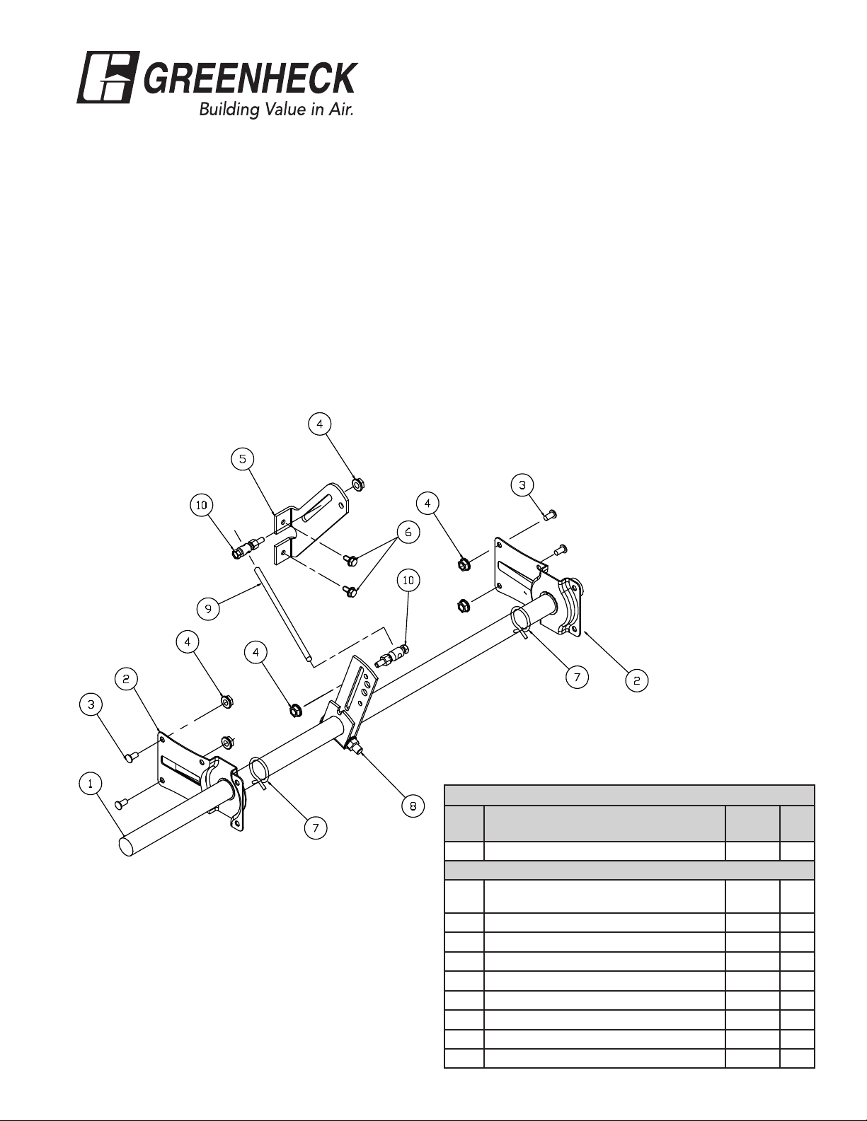
One Inch Jackshaft Kits For 48 in. Long Jackshafts
Note: Kit includes required parts for single section dampers.
1. Attach jackshaft brackets (item 2) to the frame with 1/4-20
thread studs (item 3) and 1/4-20 spinlock nuts (item 4).
2. Attach the blade bracket (item 5) to the blade with
1/4-20 x 1/2 in. machine screws (item 6).
3. Assemble the hose clamps (item 7), crankarm assemblies
(item 8) onto the jackshaft (item 1) as shown.
4. With the jackshaft positioned between the jackshaft
brackets (item 2) and hose clamps (item 7), close the
blades completely and align the crankarm assembly (item
8) with the blade bracket (item 5). Assemble the linkage
rod (item 9) and ball swivels (item 10) to the blade bracket
(item 5). The linkage rod may need to be cut down as
required depending upon the length required to connect
the ball swivels with the blade brackets.
5. Secure the assembly by sliding the hose clamps (item 7)
up to each jackshaft bracket (item 2) to secure the shaft.
6. On internal mount, the jackshaft must not extend past
the jackshaft brackets. On external mount, the jackshaft
extends past the jackshaft bracket on the actuator side 6
inches (for actuator attachment). Cut down jackshaft as
required.
Jackshaft Kits
1 in. diameter jackshaft kit - 48 in. long (Part no. 860059)
Item Description
1 1 inch jackshaft 734095 1
Hardware Kit (part no. 860058) includes the parts listed below.
2 1 in. diameter jackshaft bracket assy w
nyliner
3 Thread stud, 1/4 - 20 x 1/2 in. 415609 4
4 1/4 - 20 spinlock nut 415455 4
5 Blade bracket 653629 1
6 MS 1/4 -20 x 1/2 in. (HWH) TCS ZP 415264 2
7 1 in. hose clamp 451809 2
8 1 in. crankarm assembly 816252 1
9 5/16 in. diameter linkage rod 18 in long 656472 1
10 Ball swivel 451554 2
Part
No.
834292 2
Qty
Page 2
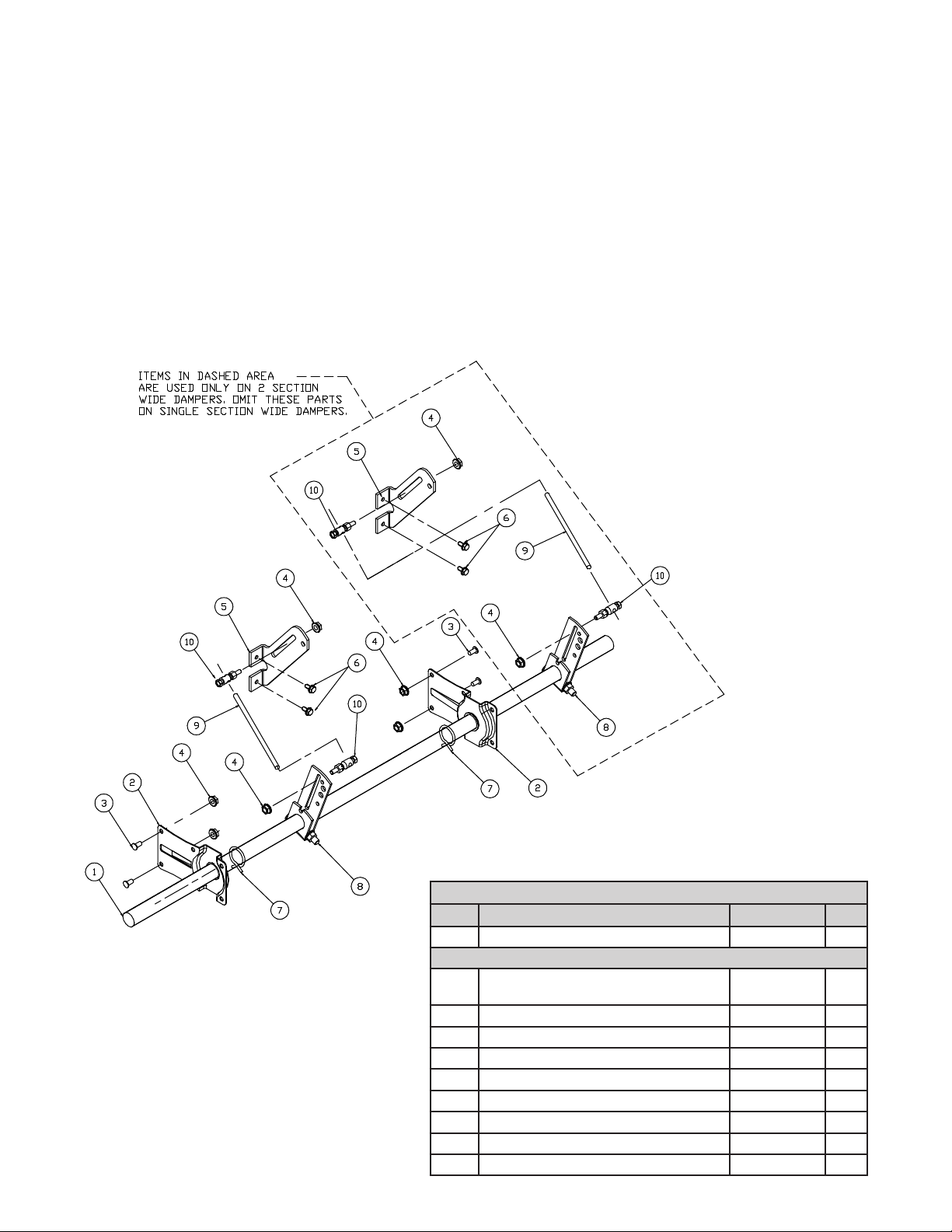
One Inch Jackshaft Kits For 60 in. Long Jackshafts
Note: Kit contains parts for 2 section wide dampers. For single section dampers, omit parts outlined. These will not be
required.
1. Attach jackshaft brackets (item 2) to frame with
1/4-20 thread studs (item 3) and 1/4-20 spinlock nuts
(item 4).
2. Attach blade bracket (item 5) to blade with 1/4-20 x 1/2
in. machine screws (item 6).
3. Assemble hose clamps (item 7), crankarm assemblies
(item 8) onto jackshaft (item 1) as shown.
4. With jackshaft positioned between the jackshaft
brackets (item 2) and hose clamps (item 7) positioned
next to jackshaft brackets (item 2), close blades
completely and align crankarm assembly (item 8) with
blade bracket (item 5). Assemble linkage rod (item 9)
and ball swivels (item 10) to blade bracket (item 5).
The linkage rod (item 9) may need to be cut down as
required depending upon length required to connect
ball swivels with blade brackets.
5. Secure assembly by sliding hose clamps (item 7) up to
each jackshaft bracket (item 2) to secure shaft.
6. On internal mount, jackshaft must not extend past
jackshaft brackets. On external mount, jackshaft
extends past jackshaft bracket on actuator side 6
inches for actuator attachment. Cut down jackshaft as
required.
1 in. diameter jackshaft kit - 60 in. long (Part no. 849576)
Item Description Part No. Qty
1 1 in. jackshaft 733765 1
Hardware Kit (part no. 860062) includes the parts listed below.
2 1 in. diameter jackshaft bracket assy w
nyliner
3 Thread stud, 1/4 - 20 x 1/2 in. 415609 4
4 1/4 - 20 spinlock nut 415455 8
5 Blade bracket 653629 2
6 MS 1/4 -20 x 1/2 “ (HWH) TCS ZP 415264 4
7 1 in. hose clamp 451809 2
8 1 in. crankarm assembly 816252 2
9 5/16 in. diameter linkage rod 18 in long 656472 2
10 Ball swivel 451554 4
834292 2
Page 3

One Inch Jackshaft Kits For 72 in. Long Jackshafts
Note: Kit contains parts for 2 section wide dampers. For single section dampers, omit parts outlined. These will not
be required.
1. Attach jackshaft brackets (item 2) to frame with
1/4-20 thread studs (item 3) and 1/4-20 spinlock nuts
(item 4).
2. Attach blade bracket (item 5) to blade with
1/4-20 x 1/2 in. machine screws (item 6).
3. Assemble hose clamps (item 7), crankarm assemblies
(item 8) onto jackshaft (item 1) as shown.
4. With jackshaft positioned between the jackshaft
brackets (item 2) and hose clamps (item 7) positioned
next to jackshaft brackets (item 2), close blades
completely and align crankarm assembly (item 8) with
blade bracket (item 5). Assemble linkage rod (item 9)
and ball swivels (item 10) to blade bracket (item 5).
The linkage rod (item 9) may need to be cut down as
required depending upon length required to connect
ball swivels with blade brackets.
5. Secure assembly by sliding hose clamps (item 7) up to
each jackshaft bracket (item 2) to secure shaft.
6. On internal mount, jackshaft must not extend past
jackshaft brackets. On external mount, jackshaft
extends past jackshaft bracket on actuator side 6
inches for actuator attachment. Cut down jackshaft as
required.
1 in. diameter jackshaft kit - 72 in. long (Part no. 849577)
Item Description Part No. Qty
1 1 in. jackshaft 733766 1
Hardware Kit (part no. 860062) includes the parts listed below.
2 1 in. diameter jackshaft bracket assy w
nyliner
3 Thread stud, 1/4 - 20 x 1/2 in. 415609 4
4 1/4 - 20 spinlock nut 415455 8
5 Blade bracket 653629 2
6 MS 1/4 -20 x 1/2 in. (HWH) TCS ZP 415264 4
7 1 in. hose clamp 451809 2
8 1 in. crankarm assembly 816252 2
9 5/16 in. diameter linkage rod 18 in long 656472 2
10 Ball swivel 451554 4
834292 2
Page 4

One Inch Jackshaft Kits For 108 in. Long Jackshafts
Note: Kit contains parts for 2 or 3 section wide dampers. For single section dampers, omit parts outlined. These will not
be required.
1. Attach jackshaft brackets (item 2) to frame with
1/4-20 thread studs (item 3) and 1/4-20 spinlock nuts
(item 4).
2. Attach blade bracket (item 5) to blade with
1/4-20 x 1/2 in. machine screws (item 6).
3. Assemble hose clamps (item 7), crankarm assemblies
(item 8) onto jackshaft (item 1) as shown.
4. With jackshaft positioned between the jackshaft
brackets (item 2) and hose clamps (item 7) positioned
next to jackshaft brackets (item 2), close blades
completely and align crankarm assembly (item 8) with
blade bracket (item 5). Assemble linkage rod (item 9)
and ball swivels (item 10) to blade bracket (item 5).
The linkage rod (item 9) may need to be cut down as
required depending upon length required to connect
ball swivels with blade brackets.
5. Secure assembly by sliding hose clamps (item 7) up to
each jackshaft bracket (item 2) to secure shaft.
6. On internal mount, jackshaft must not extend past
jackshaft brackets. On external mount, jackshaft
extends past jackshaft bracket on actuator side 6
inches for actuator attachment. Cut down jackshaft as
required.
1 in. diameter jackshaft kit - 108 in. long (Part no. 849578)
Item Description Part No. Qty
1 1 in. jackshaft 733767 1
Hardware Kit (part no. 860062) includes the parts listed below.
2 1 in. diameter jackshaft bracket assy w
nyliner
3 Thread stud, 1/4 - 20 x 1/2 in. 415609 6
4 1/4 - 20 spinlock nut 415455 12
5 Blade bracket 653629 3
6 MS 1/4 -20 x 1/2 in. (HWH) TCS ZP 415264 6
7 1 in. hose clamp 451809 2
8 1 in. crankarm assembly 816252 3
9 5/16 in. diameter linkage rod 18 in long 656472 3
10 Ball swivel 451554 6
834292 3
Page 5

Half Inch Jackshaft Kits For 36 in. Long Jackshafts
Note: Kit includes required parts for single section dampers.
1. Attach jackshaft brackets (item 2) to frame with 1/4-20
thread studs (item 3) and 1/4-20 spinlock nuts (item 4).
2. Attach blade bracket (item 5) to blade with 1/4-20 x 1/2 in.
machine screws (item 6).
3. Assemble hose clamps (item 7), crankarm assemblies
(item 8) onto jackshaft (item 1) as shown.
4. With jackshaft positioned between the jackshaft brackets
(item 2) and hose clamps (item 7)positioned next to
jackshaft brackets (item 2), close blades completely and
align crankarm assembly (item 8) with blade bracket (item
5). Assemble linkage rod (item 9) and ball swivels (item
10) to blade bracket (item 5). The connecting rod may
need to be cut down as required depending upon length
required to connect ball swivels with the blade brackets.
5. Secure assembly by sliding hose clamps (item 7) up to
each jackshaft bracket (item 2) to secure shaft.
6. On internal mount, jackshaft must not extend past
jackshaft brackets. On external mount, jackshaft extends
past jackshaft bracket on actuator side 6 inches for
actuator attachment. Cut down jackshaft as required.
½ in. diameter jackshaft kit - 36 in. long (Part no. 860061)
Item Description
1 1/2 in. jackshaft 734097 1
Hardware Kit (part no. 860057) includes the parts listed below.
2 1/2 in. diameter jackshaft bracket assy 814968 2
3 Thread stud, 1/4 - 20 x 1/2 in. 415609 4
4 1/4 - 20 spinlock nut 415455 4
5 Blade bracket 653629 1
6 MS 1/4 -20 x 1/2” (HWH) TCS ZP 415264 2
7 1/2 in. hose clamp 451786 2
8 1/2 in. crankarm assembly 812097 1
9 5/16 in. diameter linkage rod 18 in long 656472 1
10 Ball swivel 451554 2
Part
No.
Qty
Page 6

Half Inch Jackshaft Kits For 48 in. Long Jackshafts
Note: Kit includes required parts for single section dampers.
1. Attach jackshaft brackets (item 2) to frame with 1/4-20
thread studs (item 3) and 1/4-20 spinlock nuts (item 4).
2. Attach blade bracket (item 5) to blade with
1/4-20 x 1/2 in. machine screws (item 6).
3. Assemble hose clamps (item 7), crankarm assemblies
(item 8) onto jackshaft (item 1) as shown.
4. With jackshaft positioned between the jackshaft brackets
(item 2) and hose clamps (item 7)positioned next to
jackshaft brackets (item 2), close blades completely and
align crankarm assembly (item 8) with blade bracket (item
5). Assemble linkage rod (item 9) and ball swivels (item 10)
to blade bracket (item 5). The connecting rod may need to
be cut down as required depending upon length required
to connect ball swivels with a blade brackets.
5. Secure assembly by sliding hose clamps (item 7) up to
each jackshaft bracket (item 2) to secure shaft.
6. On internal mount, jackshaft must not extend past
jackshaft brackets. On external mount, jackshaft extends
past jackshaft bracket on actuator side 6 inches for
actuator attachment. Cut down jackshaft as required.
½ in. diameter jackshaft kit - 48 in. long (Part no. 860060)
Item Description
1 1/2 in. jackshaft 734096 1
Hardware Kit (part no. 860057) includes the parts listed below.
2 1/2 in. diameter jackshaft bracket assy 814968 2
3 Thread stud, 1/4 - 20 x 1/2 in. 415609 4
4 1/4 - 20 spinlock nut 415455 4
5 Blade bracket 653629 1
6 MS 1/4 -20 x 1/2 in. (HWH) TCS ZP 415264 2
7 1/2 in. hose clamp 451786 2
8 1/2 in. crankarm assembly 812097 1
9 5/16 in. diameter linkage rod 18 in long 656472 1
10 Ball swivel 451554 2
Part
No.
Qty
Page 7

NOTES
Page 8

NOTES
Our Commitment
As a result of our commitment to continuous improvement, Greenheck reserves the right to change specifications without
notice.
Specific Greenheck product warranties are located on greenheck.com within the product area tabs and in the Library
under Warranties.
®
Phone: (715) 359-6171 • Fax: (715) 355-2399 • E-mail: gfcinfo@greenheck.com • Website: www.greenheck.com
474210• Jackshafting Kits Rev. 4, January 2015 Copyright 2015 © Greenheck Fan Corporation
 Loading...