

Page 1
Document Number 464603
®
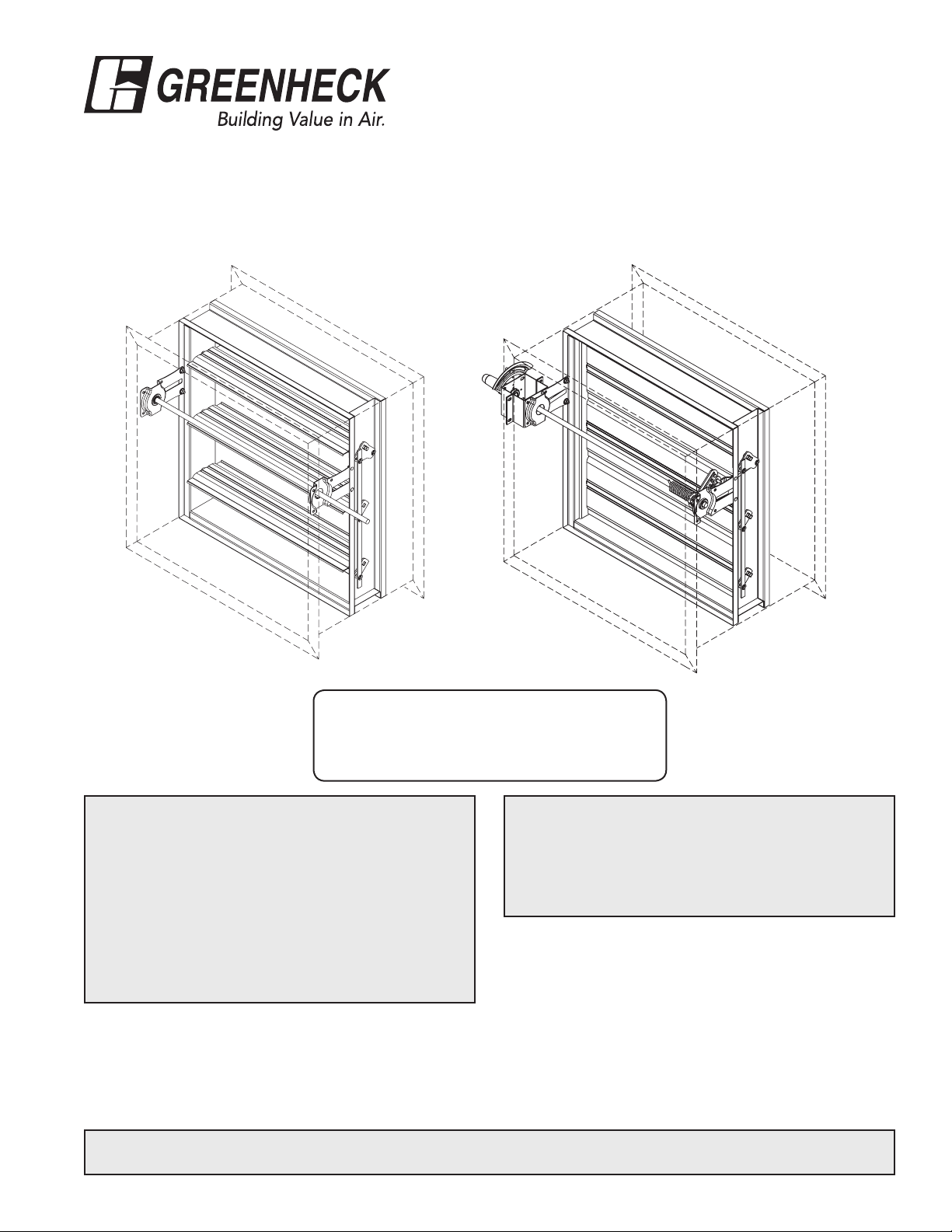
IMO-XXX & SSIMO-XXX series
Fire and Combination Fire Smoke Dampers
Vertical or Horizontal Mount
Installation, Operation and Maintenance Instructions
International Maritime Fire Test Procedure
Code
USCG Type Approved
Approval Number 164.139/0007/0
RECEIVING AND HANDLING
Upon receiving dampers, check for both obvious and
hidden damage. If damage is found, record all necessary
information on the bill of lading and file a claim with
the final carrier. Check to be sure that all parts of the
shipment, including accessories, are accounted for.
Dampers must be kept dry and clean. Indoor storage
and protection from dirt, dust and the weather is highly
recommended. Do not store at temperatures in excess of
100°F (37°C).
This manual is the property of the owner, and is required for future maintenance. Please leave it with the owner when the
job is complete.
Improper installation, adjustment, alteration,
service or maintenance can cause property damage,
injury or death. Read the installation, operating,
and maintenance instructions thoroughly before
installing or servicing this equipment.
SAFETY WARNING:
Page 2
Installation Instructions
Greenheck’s IMO dampers were tested per the International Maritime Organization’s Fire Test Procedure (FTP)
code in a Class A bulkhead and in a Class A deck for 60 minutes. The FTP code requires that the ductwork
(coaming) be insulated and that the damper be bolted or welded to the duct.
1. Insulating the Duct
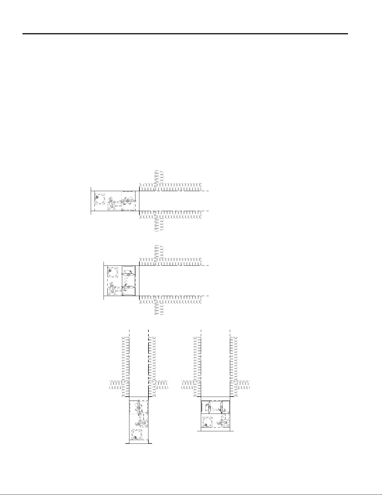
The ductwork must be insulated a minimum of 6 in. (152mm) on the damper side and 18 in. (457mm) on the
non-damper side (see figures 1-4). Any US Coast Guard type approved insulation with an A60 rating can be
used. The insulation is to be installed on the duct with 0.106 in. (2.7mm) steel pins and 1.12 x 1.24 x 0.4 in.
(28 x 31 x 10mm) steel clips.
2. Attaching Damper to Duct
The damper can be installed to the duct using either bolts or welding. If bolts are used , they are to be a
minimum of 0.375 in. (9.5mm) diameter and 1 in. (25mm) long. The fasteners should be spaced 6 in. (152mm)
OC and a maximum of 2 in. (51mm) from the corners.
Horizontal Airflow- Vertical Damper mount
6 in. (152mm)
18 in. (457mm)
Fig. 1
6 in. (152mm)
18 in. (457mm)
Fig. 2
Vertical Airflow- Horizontal Damper mount
IF HEIGHT <=11.00 in. (279mm)
IF HEIGHT >11.00 (279mm)
18 in. (457mm)
6 in. (152mm)
Fig. 3
18 in. (457mm)
6 in. (152mm)
Fig. 4
Page 3
Size Limitations
Damper model Maximum Single Maximum Overall size for
Section size Multi-section dampers
IMO-310 32 in. x 32 in. 64 in. x 32 in.
(813mm x 813mm) (1626mm x 813mm)
SSIMO-310 32 in. x 32 in. 64 in. x 32 in.
(813mm x 813mm) (1626mm x 813mm)
IMO-311 32 in. x 32 in. 64 in. x 32 in.
(813mm x 813mm) (1626mm x 813mm)
SSIMO-311 32 in. x 32 in. 64 in. x 32 in.
(813mm x 813mm) (1626mm x 813mm)
Manually operated dampers (IMO-310 & SSIMO-310)
Manually operated dampers utilize a spring and fusible link assembly to close the damper during elevated
temperature conditions. No electrical power is required for these models.
Motor operated dampers (IMO-311 & SSIMO-311)
Motor operated dampers are supplied with an electric thermal response device which cuts power to the spring
return actuator upon sensing an elevated temperatures. See below for electrical connections.
Connection and Operation of Temperature
Response Devices (RRL standard, OCI option,
and PRV option)
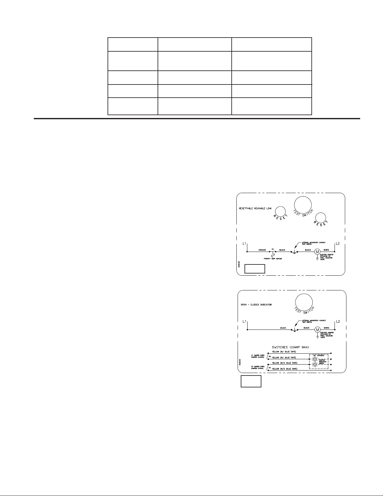
RRL - Dampers will be supplied with a thermostat-type
temperature response device, as a standard. The device is
a RRL (resettable link device), which only incorporates one
thermostat and therefore the damper remains closed as
soon as its sensor temperature is reached. The RRL does
not contain blade indication switches. Refer to Figure 5 for
wiring of the RRL thermostat.
If RRL is ordered with a pneumatic actuator, an EP switch
is required with an appropriate electric power circuit to
allow the electric thermostat to control the pneumatic
actuator.
OCI - The OCI (open or closed indicator) option contains
a single pole, double throw switch used to indicate the
damper blade
position. The switch provides a positive open or closed
signal when used in conjunction with remote indicator
lights. Refer to Fig. 6 for wiring of the OCI option.
PRV - The PRV (pneumatic relief valve) option is heat
responsive device used with pneumatic actuators. This
can be used in place of EP switch where a RRL is used.
The PRV activates when temperature in excess of the
temperature of the fusible link are detected. When the
fusible link melts, air from the actuator is exhausted to
close the dampers. Pneumatic actuators are to be piped
per local code.
Fig. 5
Fig. 6
RATINGS
Integral Switch Type: Single Pole, double throw
RRL Wiring
OCI Wiring
Electrical Capacity: 10 Amps, 1/3 hp, 120 or 240 Vac
1/2 Amp, 125 Vdc; 1/4 Amp 250 Vdc
5 Amps, 120 Vac “L” (lamp load)
1.0 Amps, 24 Vac
1.5 Amps, 24 Vdc
Temperature Limit: 165° F (standard primary sensor)
212° F (optional primary sensor )
Page 4
Damper Maintenance
Dampers do not typically require maintenance as long as they are kept dry and clean. If cleaning is necessary,
use mild detergents or solvents. If lubrication is desired for components such as axle bearings, jackshaft
bearings and jamb seals, do not use oil-based lubricants or any other lubricants that attract contaminants such
as dust.
Dampers and their actuator(s) must be maintained, cycled, and tested in accordance with:
• The latest editions of NFPA 80, 90A, 92A, UL864, and local codes.
• Actuator manufacturer recommendations.
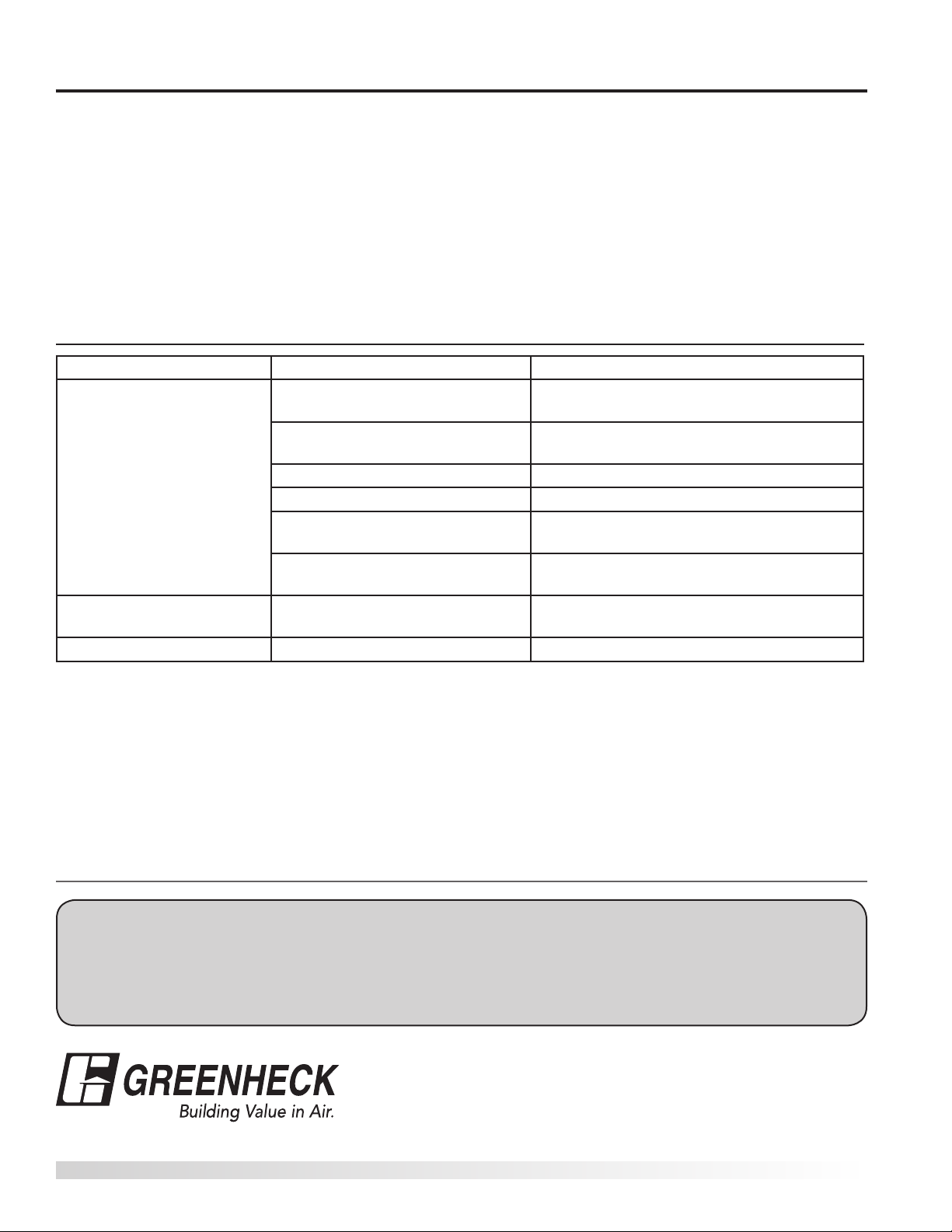
Damper Troubleshooting
The following is a possible cause and correction list for common concerns with the dampers.
Symptom Possible Cause Corrective Action
Frame is 'racked' causing blades
to bind on jamb seals
Actuator linkage loose Close damper, disconnect power, adjust and
Damper does not fully open
and/or fully close
RRL or TOR sensor tripped Heat Push reset button located on backside of
Damper does not operate No power supplied to the actuator Supply power
Defective motor Replace
Screws in damper linkage Locate screws and remove
Actuator linkage hitting wall or
floor
Contaminants on damper Clean with a non-oil based solvent (see
Adjust frame such that it is square and
plumb
tighten linkage
Damper installed too far into wall. Move out
to line designated on damper label.
Damper Maintenance)
RRL or TOR.
Our Commitment
As a result of our commitment to continuous improvement, Greenheck reserves the right to change specifications without notice.
Specific Greenheck product warranties are located on greenheck.com within the product area tabs and in the Library under Warranties.
®
Phone: (715) 359-6171 • Fax: (715) 355-2399 • E-mail: [email protected] • Website: www.greenheck.com
464603• Marine IMO Rev. 4, October 2012 Copyright 2012 © Greenheck Fan Corporation
 Loading...