

Page 1
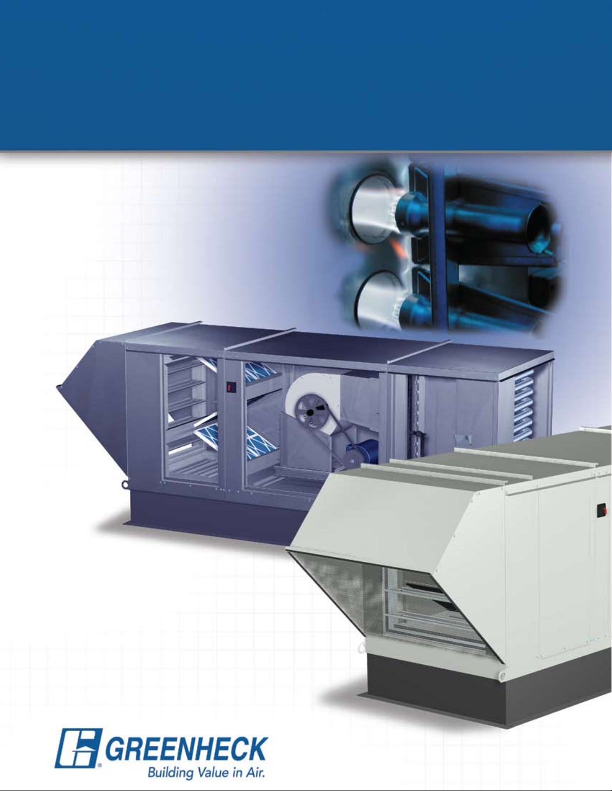
Modular Heating & Ventilating Unit
Model IGX-HV
• Indirect Gas-Fired Heating
• Evaporative • Chilled Water • DX Cooling
October
2008
Page 2
PRODUCT FEATURES
Model IGX-HV
Indirect Gas-Fired
Heating and Ventilating Unit
Indoor/Outdoor Installations
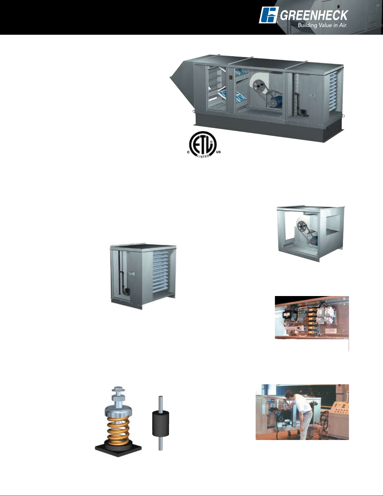
All Greenheck model IGX-HV units feature 80%
efficient indirect gas-fired furnace(s), filtered
mixing box section, fan section, and are ETL listed
to the UL-1995 test standard. Heating capacities
range from 100,000 to 1,200,000 BTU/Hr and air
flow volumes are available up to 15,000 cfm.
A modular design concept enables the flexibility
to customize each product for its application. Modules
are then factory assembled and wired to minimize field
installation labor. The result is a semi-custom product at
an attractive cost.
IGX-HV shown with horizontal discharge.
Reliable Fan Performance
Air performance ratings from Greenheck’s AMCA
registered test chamber ensure accurate data.
Indirect Gas-Fired Furnaces
The Greenheck furnace is designed for top-notch
performance and long life, combining quality
components with expert craftsmanship. Unique to
our furnace is a post purge cycle, which runs the
combustion fan after the unit is shut down to vent
hot air and moisture out of
the heat exchanger. The
elimination of these corrosion
catalysts adds years to the
life of the heat exchanger.
Other key features of our
furnace are listed below:
• Power vented
• 80% thermal efficiency
• Seamless tubes
• Electronic staged gas controls
• Electronic modulating gas controls
• Aluminized steel or stainless steel heat exchanger
• Direct spark ignition system
• Easy access burner controls
• ETL listed to ANSI Standard Z83.8
• Solid state automatic ignition module
Fans are constructed of heavy gauge steel and
designed for high efficiency
and low sound levels.
Wheels are statically and
dynamically balanced
to ensure vibration free
operation.
Control Center
The control center includes
the following standard components:
• Magnetic motor starter with solid state overload
protection
• Control transformer
• Disconnect switch
• Separately fused motor
• Distribution terminal strip
Premium grade control
components are selected for reliable operation. All
electrical components are UL Listed, recognized or
classified. Control centers are factory prewired for
single point power connection.
Vibration Isolators
The entire fan and
motor assembly is
mounted on vibration
isolators to minimize
noise transmission into
the building. Neoprene
isolators are standard on
all units, spring isolators
are optional.
2
Factory Wired
and Tested
All units are tested
prior to shipment.
Units are checked for
vibration and proper
operation.
Page 3
CONTROL OPTIONS
Suppl
y
Return Ai
r
70% - 100
%
Outdoor Air
0% - 30%
Suppl
y
Return Ai
r
70% - 100
%
Outdoor Air
0% - 30%
Suppl
y
Return Ai
r
25% - 100
%
Outdoor Air
30% - 75%
Suppl
y
Return Ai
r
70% - 100
%
Suppl
y
Return Ai
r
25% - 100
%
Suppl
y
Return Ai
r
100
%
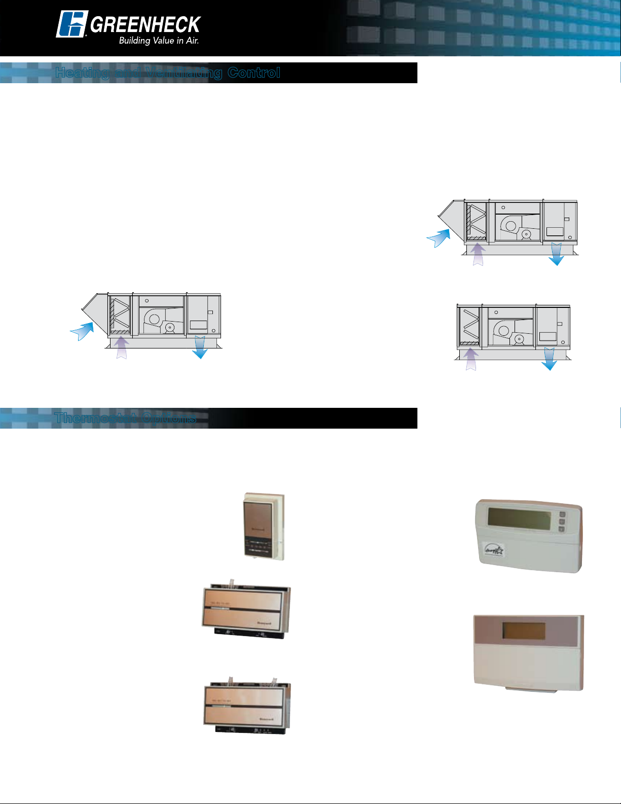
Heating and Ventilating Control
Three heating and ventilating options are available to provide proper tempering and fulfill varying requirements for
fresh outdoor air. In all cases, heating and cooling functions are controlled by a Greenheck room thermostat or a
DDC system (by others).
HV1: 0%-30% Minimum Outdoor Air
HV1 is the most common among
heating and ventilating units, allowing
you to set the minimum outdoor air
volume between 0 and 30% of the total
supply air volume. With the relatively
low percentage of outdoor air, mixed
air temperatures are mild and stable.
1-stage heating and/or cooling is
recommended. (2-stage or electronic
modulation is optional).
Thermostat Options
HV2: 30%-75% Minimum Outdoor Air
The HV2 option is required when the minimum outdoor air volume
exceeds 30% of the total supply air volume. With higher outdoor air
volumes, mixed air temperatures
can vary greatly. Accordingly,
2-stage heating and/or cooling is
recommended. Also, an airstream
override thermostat is standard
with HV2 to prevent cold air
discharge (below 55˚ F) when the
thermostat is satisfied. (electronic
modulation is optional).
HV3: 100% Return Air
The HV3 option is available when no
outdoor air is needed. With relatively
stable return air conditions, 1-stage
heating and/or cooling is strongly
recommended. (2-stage or electronic
modulation is optional).
Basic bimetal thermostats with mercury switches or fully programmable electronic thermostats are available as
part of your IGX-HV system. Match your heating, cooling, staging, and operational requirements to the appropriate
thermostat.
TC1: 1-Stage Heating / Cooling
TC1 is a coiled bimetal thermostat
used for single-stage heating, cooling
or heating-cooling systems.
TC4: Programmable
TC4 has full seven-day program
capability. The thermostat can
be set for four times and eight
temperature settings each day of
the week. It can control up to two
stages of heating and two stages
TC2: 2-Stage Heating
of cooling.
TC2 is a coiled bimetal
thermostat used for 2-stage
heating systems.
TC5: Deluxe Programmable
TC5 has full seven-day program
capability. The thermostat can
be set for two occupied and two
TC3: 2-Stage Heating / 2-Stage Cooling
TC3 is a coiled bimetal
thermostat used for 2-stage
heating, cooling or heatingcooling systems. It includes
an adjustable heat anticipator,
stops, and a locking cover.
unoccupied times with adjustable
temperature settings for each day
of the week. It can control up to
three stages of heating and two
stages of cooling. The Intelligent Fan™ feature energizes the
fan continuously during occupied mode and intermittently
with a call for heating or cooling in unoccupied mode.
3
Page 4

MIXING BOX CONTROLS
Suppl
y
Return Ai
r
Outdoor Air
The mixing box (shown at right) includes
outdoor air and return air low leakage
control dampers in a face and bypass
configuration. Either two inch pleated
or aluminum mesh filters are available
within the mixing box section. Double wall
construction is optional.
A mixing box control option must be
specified for every IGX-HV unit. Greenheck
offers eight mixing box control options
that accommodate a wide variety of
applications. The four EC and four MB
options are described below. Specify only
one control box option per unit.
Mixing Box Controls with Economizer Cooling
The economizer controls package enables free cooling using outdoor air. All EC options include a modulating
actuator for controlling outdoor and return air dampers, and a minimum outdoor air positioner. During a call for
heating the economizer is locked out and the outdoor air damper holds at the minimum position.
EC1: Outdoor Temperature Reference
The economizer controller positions the mixing box
dampers to achieve 55° F mixed temperature when
the thermostat calls for cooling AND the outdoor air
temperature is below the economizer
setpoint. If outdoor air temperature is
between 55° F and the economizer
setpoint, the dampers will modulate
to the 100% outdoor air position.
Above the setpoint, the outdoor
air damper is held at the minimum
position. The setpoint is field
adjustable and the outdoor air sensor
is factory mounted.
EC3: Airstream Temperature Reference
The economizer controller compares the temperatures
of the outdoor air and return air when the thermostat
calls for cooling. The mixing box dampers are then
positioned to maximize the
airflow of the cooler airstream.
When outdoor air temperature
is sufficiently cool, the mixing
box dampers will modulate to
provide 55° F mixed air. The
outdoor air sensor is factory
mounted. The return air sensors
are field installed.
EC2: Outdoor Enthalpy Reference
Same as EC1, except economizer setpoint is based on
outdoor air enthalpy.
EC4: Airstream Enthalpy Reference
Same as EC3, except airstream enthalpy values are
compared.
Mixing Box Controls (no economizer)
In addition to the EC options described above, Greenheck offers four MB mixing box control options for
applications where a factory provided economizer package is not desired.
MB1: Minimum Outdoor Air Positioner
The MB1 option includes a modulating
actuator and potentiometer that control
the outdoor air and return air damper
positions. When the unit is energized,
the dampers will travel to the position
corresponding to the potentiometer
setting, providing the desired amount of outdoor air.
When the unit is powered off, the outdoor air damper
closes to prevent backdrafting. To adjust the damper
settings, simply dial the potentiometer (shown above) to
desired operating position of the outdoor air damper.
MB2: 2-10 Volt External Signal
The MB2 option includes a modulating actuator that is
controlled by an external 2-10 volt signal. This option
is appropriate for applications that call for a building
4
automation system that will control the mixing box
dampers.
MB3: 4-20 mA External Signal
The MB3 option includes a modulating actuator that is
controlled by an external 4-20 mA signal. Like the MB2
option, this option is appropriate for applications that
call for a building automation system that will control the
mixing box dampers.
MB4: Manual Quadrant
The MB4 option consists of a manual
quadrant that enables the outdoor air
and return air dampers to be secured
into a single position. The primary
function is to introduce the specified minimum outdoor
air volume during operation. Dampers remain in the
same position when the unit is powered off.
Page 5

Evaporative Cooling
COOLING OPTIONS
An evaporative cooling section includes a galvanized
steel housing with a louvered intake, two inch aluminum
mesh filters and a stainless steel evaporative cooling
media housing. The evaporative cooling media is
Munters CELdek or GLASdek and has a depth of
12 inches for 90% cooling effectiveness.
Drain and overflow lines are conveniently stubbed
through the side of the cooling section. The supply line
connection is field located where convenient.
IGX-HV airflow capacity for evaporative cooling is up
to 14,000 cfm. Below 9,000 cfm, evaporative cooling
modules ship attached and factory wired. Field
attachment is required for airflow above 9,000 cfm.
Mixing Box Controls:
Mixing box control option EC1 is recommended for use
Cooling Coils
Model IGX-HV boasts the flexibility of Chilled Water or
Direct Expansion (DX) cooling with capacity to 11,000
CFM. The cooling section includes the cooling coil,
stainless steel drain pan and insulated double wall
construction. Drain and coil connections are stubbed
through the wall for convenience.
For proper coil sizing, use Greenheck’s Computer Aided
Product Selection (CAPS) program or contact your local
representative. Four and six row coils are available.
Cooling coil sections are installed downstream of the
mixing box section for a draw through arrangement.
This provides a streamlined transition to adjacent
IGX-HV sections. DX coils require remote condensing
units.
Mixing Box Controls:
All MB and EC mixing box control options are available
with chilled water or DX cooling coils.
with evaporative
cooling. On a call
for cooling when
the outdoor air
temperature is below
the economizer
setpoint, the
dampers modulate
to provide cool
mixed temperatures
down to 55° F. When
the outdoor air is
above the economizer setpoint, the evaporative cooling
section is energized and the dampers travel to the 100%
outdoor air position.
The MB mixing box options are NOT recommended in
conjunction with evaporative cooling.
For economizer
climates, the
EC1 option is
recommended.
Mixing box options
operate as described
on page 4.
Thermostats:
The cooling coil
and MB mixing box
control options may
use a 1-stage (chilled
water or single stage DX) or 2-stage (dual stage DX)
cooling thermostat.
The cooling coil and EC mixing box control options
require a 2-stage cooling thermostat. Economizer
represents the first stage of cooling and a single DX
stage or chilled water coil represents the second stage
of cooling.
Mixing Box Selection Guide
EC Options MB Options
EC1 EC2 EC3 EC4 MB1 MB2 MB3 MB4
No Cooling Yes Yes Yes Yes Yes Yes Yes Yes
Evaporative
Cooling
Chilled Water or
DX Cooling
*Two-stage cooling thermostat required. Boldface type indicates factory recommended options.
Yes
Yes* Yes* Yes* Yes* Yes Yes Yes Yes
Yes
Not
Recommended
Not
Recommended
No No No No
5
Page 6

AIR PERFORMANCE
Housing Size 12
MODEL CFM
800
IGX-HV-108
IGX-HV-109
IGX-HV-110
1,000
1,200
1,500
2,000
2,500
2,000
2,500
3,000
Housing Size 22
MODEL CFM
2,600
IGX-HV-112
IGX-HV-115
3,500
4,400
5,000
6,000
7,000
TOTAL STATIC PRESSURE in inches of WG
0.50 0.75 1.00 1.25 1.50 1.75
RPM 993 1109 1216 1311 1399
BHP .21 .26 .31 .35 .40
RPM 1112 1228 1325 1415 1500 1579
BHP .34 .41 .47 .53 .59 .65
RPM 1238 1347 1445 1530
BHP .51 .59 .68 .75
RPM 880 1014 1140 1255 1361 1460
BHP .36 .45 .54 .63 .73 .84
RPM 1004 1113 1219 1321 1417 1510
BHP .65 .77 .90 1.0 1.1 1.3
RPM 1154 1244 1329 1419 1503 1587
BHP 1.1 1.2 1.4 1.6 1.7 1.9
RPM 805 912 1013 1110 1199
BHP .48 .59 .71 .84 .96
RPM 906 995 1082 1166 1247 1325
BPH .79 .93 1.07 1.21 1.36 1.51
RPM 1014 1097 1172 1244 1315 1386
BHP 1.22 1.39 1.55 1.72 1.88 2.05
TOTAL STATIC PRESSURE in inches of WG
0.50 0.75 1.00 1.25 1.50 1.75
RPM 662 761 853 934 1009
BHP .58 .72 .86 1.0 1.2
RPM 756 839 920 993 1065 1133
BHP 1.0 1.3 1.5 1.7 1.9 2.1
RPM 871 939 1006 1073 1137 1197
BHP 1.8 2.1 2.4 2.6 2.9 3.1
RPM 671 741 808 871 931 986
BHP 1.7 2.0 2.3 2.6 2.9 3.2
RPM 749 812 870 929 982 1035
BHP 2.6 2.9 3.3 3.7 4.0 4.4
RPM 833 889 943 994 1044 1093
BHP 3.7 4.2 4.6 5.0 5.5 5.9
Maximum
Furnace Size
(Input MBH)
100
150
150
200
250
250
250
250
250
Maximum
Furnace Size
(Input MBH)
350
500
600
600
600
600
Housing Size 32
MODEL CFM
TOTAL STATIC PRESSURE in inches of WG
0.50 0.75 1.00 1.25 1.50 1.75
RPM 566 627 685 738 790 839
BHP 2.1 2.5 2.8 3.2 3.6 4.0
RPM 636 690 740 790 836 880
BHP 3.3 3.8 4.2 4.7 5.1 5.6
RPM 712 759 805 849 891 933
BHP 5.0 5.5 6.1 6.6 7.1 7.7
RPM 542 590 634 678 723 765
BHP 3.6 4.0 4.5 5.0 5.6 6.1
RPM 633 672 711 748 784 820
BHP 6.3 6.9 7.5 8.1 8.7 9.3
RPM 731 763 795 829 861 892
BHP 10.2 10.9 11.6 12.3 13.1 13.8
IGX-HV-118
IGX-HV-120
7,000
8,500
10,000
10,000
12,500
15,000
Note: The air performance data shown does not include internal static pressure losses due to items such as
filters, dampers and furnaces. For exact air performance data based on specific unit configuration, use the
Greenheck CAPS selection program.
6
Maximum
Furnace Size
(Input MBH)
1,050
1,200
1,200
1,200
1,200
1,200
Page 7

ACCESSORIES
Air Filter Gauge
Indicates when filters become
dirty. An indicator light may be
wall/beam mounted or provided
with a remote control panel.
Motorized Dampers
Discharge dampers are available
to prevent backdrafts when
the fan is not in operation.
Mixing box dampers are factory
mounted and wired.
Fan Spring Vibration Isolation
Spring vibration isolators are available in lieu of
neoprene isolators for housing sizes H22 and H32
(fan sizes 112 and larger).
115 Volt Service Receptacle
A 115 volt GFCI outlet is mounted externally in a NEMA
3R box for the convenience of field service personnel. A
separate 115 volt power source is required.
Roof Curbs
Factory provided roof
curbs are available to
ensure compatibility
between make-up air
unit and roof curb.
Standard construction is
galvanized steel.
G90
Propane Gas Conversion Kit
Greenheck’s indirect gas furnaces are ETL listed for
both Natural Gas or LP.
Duct Adapter
Duct adapters are optional with factory supplied curbs
and provide an easy method for attaching ductwork to
the curb.
Double Wall Construction
An interior metal liner is available to isolate insulation
from the airstream. One-inch thick insulation is included
with this option.
Gas Pressure Regulator
Required if building gas line pressure
exceeds IGX-HV maximum inlet gas
pressure of 14 in. wg.
Smoke Detector
A 12/24 VDC Photoelectric smoke detector is available
for duct mounting. Typical operating temperature range
is 32°F to 131°F (0°C to 55°C).
Discharge Diffuser
Available as either 3-way
diffuser for horizontal
discharge or 4-way
diffuser for downblast
discharge.
Special Coatings
Greenheck’s Permatector powder paint is available if a
painted look is desired and recommended for outdoor
installations near salt water shorelines. Decorative
baked enamel paints are also available in a variety of
colors to match existing building fixtures. Consult your
Greenheck representative for paint selections.
Weatherhood
A galvanized steel mist eliminating intake hood
is standard on outdoor IGX-HV models. The mist
eliminating intake hood provides a double layer of
protection against moisture entering the mixing box
section.
3-Way Diffuser
Airstream Override
This option prevents the discharge air temperature
from dropping below 55°F after the call for heating has
ended.
Warm-Up Control
Available with the TC5
thermostat. The thermostat
may be programmed to
provide a warm-up cycle prior
to the occupied start time. This
ensures immediate comfort
and proper air quality as people enter the occupied
areas.
7
Page 8

Specifications
General: Heating and Ventilating unit shall be as
manufactured by Greenheck or approved equal provided
all specifications are met. Greenheck Model IGX-HV is
used as the basis of design. Performance shall be as
scheduled on plans.
Furnace: Indirect gas fired furnace shall be 80% efficient,
ETL Listed and have a blow through fan design. Furnace
shall be capable of operation with Natural or LP gas and
have a power venting system with post purge cycle. The
heat exchanger shall be constructed of aluminized steel
or stainless steel. Standard furnace features shall include
main gas pressure regulator, main gas valve, electronic
staged controls, direct spark ignition system, high limit and
a 24 volt control transformer. Furnace shall be insulated
and have double wall construction.
Temperature Control: Heating and cooling output shall
be controlled by a room thermostat to maintain desired
room temperature. Economizer control shall provide the
first stage of cooling, where specified. Furnaces shall
provide one or two stages of heat output control.
Unit Casing and Frames: All frames and panels shall
be G90 galvanized steel. Where top panels are joined
there shall be a standing seam to insure positive weather
protection. All metal-to-metal surfaces exposed to the
weather shall be sealed, requiring no caulking at job
site. All components shall be easily accessible through
removable doors.
Insulation: Models provided with a mixing box shall be
insulated from the return section through to the supply
discharge. Insulation shall be in accordance with NFPA
90A and tested to meet UL 181 erosion requirements.
Double wall shall be provided if specified.
Fan Section: Centrifugal fans shall be double width,
double inlet. Fan and motor shall be mounted on a
common base and shall be internally isolated. All blower
wheels shall be statically and dynamically balanced.
Ground and polished steel fan shafts shall be mounted in
permanently lubricated ball bearings (up to size 118) or
ball bearing pillow blocks (size 120 and larger). Bearings
shall be selected for a minimum (L10) life in excess of
100,000 hours at maximum cataloged speeds.
Motors and Drives: Motors shall be energy efficient,
complying with EPACT standards, for single speed
ODP and TE enclosures. Motors shall be permanently
lubricated, heavy duty type, matched to the fan load and
furnished at the specified voltage, phase and enclosure.
Drives shall be sized for a minimum of 150% of driven
horsepower. Pulleys shall be cast and have machined
surfaces, 10 horsepower and less shall be supplied with
an adjustable drive pulley.
Electrical: All internal electrical
components shall be prewired for
single point power connection. All
electrical components shall be UL
listed, recognized or classified where
applicable and wired in compliance
with the National Electrical Code.
Control center shall include motor
starter, control circuit fusing, control
transformer for 24 VAC circuit,
integral disconnect switch with
separate motor fusing and terminal
strip. Contactors, Class 20 adjustable
overload protection and single phase
protection shall be standard.
Filter Section: Filters shall be
mounted in a V-bank arrangement
such that velocities across the filters
do not exceed 550 feet per minute. Filters shall be easily
accessible through a removable access panel.
Weatherhood: Weatherhood shall be mist eliminating
type, constructed of G90 galvanized steel. The
weatherhood shall contain drainable blade louvers, backed
by mist eliminating filters to prevent moisture intake.
Mixing Box: Mixing box shall contain outside air and
return air dampers with low leak, pressure activated,
extruded vinyl blade seals, aluminum jamb seals, Belimo
actuator and 30% efficient pleated filters in a V-bank
arrangement. The mixing box shall modulate the amount
of outdoor and return air by use of dampers. Input signal
for return damper shall be from potentiometer, 2-10 volt
signal, 4-20 mA signal or manual quadrant controller.
Evaporative Cooling Section: Evaporative cooling
section shall include a galvanized steel housing with
louvered intake, two inch aluminum mesh filters and a
stainless steel evaporative cooling module all provided
by the make-up air unit manufacturer. The louver shall
be stationary type with drainable blades, designed to
withstand wind loads of 25 PSF and bear the AMCA seal.
Evaporative cooling media shall be Munters CELdek with
a depth of 12 inches for a cooling effectiveness of 90%.
Drain and overflow connections shall be piped through the
side of the evaporative cooling section.
Cooling Coil: Direct expansion (DX) or chilled water
coil shall be factory tested and rated in accordance with
ARI 410. Coils shall have copper tubes with permanently
expanded aluminum fins, 12 fpi or less. DX coils shall be
equipped with distributors to receive expansion valves at
the liquid connections. Drain pans shall extend at least
12 inches downstream of coil and be sloped to drain
connection.
Copyright © 2008 Greenheck Fan Corp. • IGX-HV Rev. 2 October 2008 SN
 Loading...