

Page 1
Part # 464104
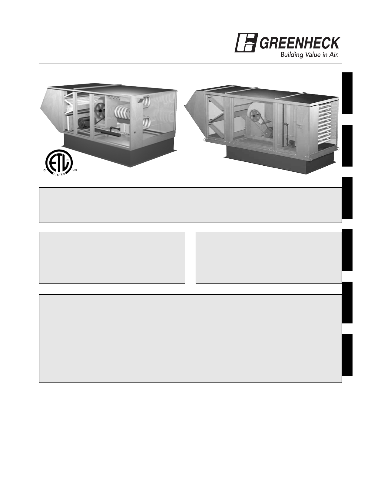
MODELS IG / IGX
Make-Up Air Unit
Installation, Operation and Maintenance Manual
Indirect Gas Fired Unit Installations
Units are listed for installation in the United States and Canada
• Installation of gas fired duct furnaces must conform with local building codes. In the absence of local
codes, installation must conform to the National Fuel Gas code, ANSI Z223.1 or in Canada,
CAN/CGA-B149 installation codes.
• All electrical wiring must be in accordance with the regulation of the National Electric Code,
ANSI/NFPA No. 70.
• Unit is approved for installation downstream from refrigeration units. In these conditions, condensate
could form in the duct furnace and provision must be made to dispose of the condensate.
**WARNING**
Improper installation, adjustment, alteration, service or maintenance can cause property damage,
injury or death. Read the installation, operating, and maintenance instructions thoroughly before
installing or servicing this equipment.
**FOR YOUR SAFETY**
The use and storage of gasoline or other
flammable vapors and liquids in open
containers in the vicinity of this appliance is
hazardous.
**FOR YOUR SAFETY**
If you smell gas:
1. Open windows.
2. Don’t touch electrical switches.
3. Extinguish any open flame.
4. Immediately call your gas supplier.
MaintenanceTroubleshootingOperationStart-UpInstallation Reference
Report any damaged equipment to the shipper immediately!
All units are shipped on a skid or packaged to minimize damage during shipment. The transporting carrier has
the responsibility of delivering all items in their original condition as received from Greenheck. The individual
receiving the equipment is responsible for inspecting the unit for obvious or hidden damage, recording any
damage on the bill of lading before acceptance and filing a claim (if required) with the final carrier. Some
accessory items are stored inside the unit during shipping. Care must be taken during installation to prevent
damage to units.
®
Page 2

2
TABLE OF CONTENTS
STORAGE
When a unit is not going to be in service for an extended period of time, certain procedures should be followed
to keep the unit in proper operating condition:
• Plug all piping
• Rotate fan wheel monthly and purge bearings once every one to three months (depending on environment)
• Energize fan motor once every three months
• Store belts flat to keep them from warping and stretching
• Store unit in location without vibration
• Cover unit with tarp to protect from dirt and moisture
• After storage period, purge grease before putting fan into service
NOTE!
Do not cover unit with a black tarp, this would
promote condensation.
NOTE!
Improper storage which results in damage to the
unit will void the warranty.
Installation
Unit - Indoor . . . . . . . . . . . . . . . . . . . . . . . . . .3
Unit - Arrangement DB/HZ . . . . . . . . . . . . . . .4
Unit - Arrangement DBC . . . . . . . . . . . . . . .5-6
Venting - Outdoor . . . . . . . . . . . . . . . . . . . . . . .7
Venting - Indoor (All Units) . . . . . . . . . . . . . . . .8
Venting - Standard Indoor . . . . . . . . . . . . . . . .9
Venting - Concentric (General) . . . . . . . . . . .10
Venting - Concentric (Horizontal) . . . . . . .11-12
Venting - Concentric (Vertical) . . . . . . . . .13-14
Venting - Two Pipe (Horizontal) . . . . . . . .15-16
Venting - Two Pipe (Vertical) . . . . . . . . . .17-18
Electrical . . . . . . . . . . . . . . . . . . . . . . . . . .19-21
Gas Piping . . . . . . . . . . . . . . . . . . . . . . . . .22-23
Evaporative Cooler Piping . . . . . . . . . . . .24-25
Water Wizard™ Evaporative Control . . . . . .26
Direct Expansion (DX) Coil Piping . . . . . .27-29
Chilled Water Coil Piping . . . . . . . . . . . . . . . .30
Building Pressure Control . . . . . . . . . . . . . . .31
I
Start-Up
Blower . . . . . . . . . . . . . . . . . . . . . . . . . . . .32-33
Furnace (All Units) . . . . . . . . . . . . . . . . . . . . .34
Furnace (Single Stage) . . . . . . . . . . . . . . . . . .35
Furnace (2:1 Staged) . . . . . . . . . . . . . . . . . . .36
Furnace (8:1 Staged) . . . . . . . . . . . . . . . .37-41
Furnace (2:1 Modulation) . . . . . . . . . . . . . . . .42
Furnace (4:1 Modulation) . . . . . . . . . . . . .43-46
Mixing Box . . . . . . . . . . . . . . . . . . . . . . . .47-48
Water Wizard™ Evaporative Controller . .49-50
Evaporative Cooling . . . . . . . . . . . . . . . . . . . .51
S
Operation
Furnace (2:1 Staged) . . . . . . . . . . . . . . . . . . .52
Furnace (2:1 Modulation) . . . . . . . . . . . . . . . .53
4:1 Modulation / 8:1 Staged Controller . .54-55
Furnace (4:1 Modulation) . . . . . . . . . . . . . . . .56
Furnace (8:1 Staged) . . . . . . . . . . . . . . . . . . .57
Recirculating/VAV Units . . . . . . . . . . . . . . . . .58
Economizer . . . . . . . . . . . . . . . . . . . . . . . . . . .59
Water Wizard™ Evaporative Controller . . . .60
O
Troubleshooting
Blower . . . . . . . . . . . . . . . . . . . . . . . . . . . . . . .61
Motor . . . . . . . . . . . . . . . . . . . . . . . . . . . . . . .62
Airflow . . . . . . . . . . . . . . . . . . . . . . . . . . . .63-64
Vibration . . . . . . . . . . . . . . . . . . . . . . . . . . . . .65
Furnace (Single Stage or 2:1 Staged) . . . . . .66
Furnace (2:1 Modulating) . . . . . . . . . . . . . . . .67
Furnace (4:1 Modulation) . . . . . . . . . . . . .68-69
Furnace (8:1 Staged) . . . . . . . . . . . . . . . .70-71
Water Wizard™ Evaporative Controller . . . .72
T
Reference
Vent Connections . . . . . . . . . . . . . . . . . . .80-81
Model IG (Single Stage or 2:1 Staged) . . . . .82
Model IG (8:1 Staged) . . . . . . . . . . . . . . . . . .83
Model IG (2:1 Modulating) . . . . . . . . . . . . . . .84
Model IG (4:1 Modulating) . . . . . . . . . . . . . . .85
Model IGX (Blower Control Center) . . . . . . . .86
Model IGX (Single Stage or 2:1 Staged) . . . .87
Model IGX (8:1 Staged) . . . . . . . . . . . . . . . . .88
Model IGX (2:1 Modulating) . . . . . . . . . . . . . .89
Model IGX (4:1 Modulating) . . . . . . . . . . . . . .90
Performance Table . . . . . . . . . . . . . . . . . . . . .91
Warranty . . . . . . . . . . . . . . . . . . . . . .Backcover
Maintenance
Routine . . . . . . . . . . . . . . . . . . . . . . . . . . .73-75
Fall . . . . . . . . . . . . . . . . . . . . . . . . . . . . . . .76
Log . . . . . . . . . . . . . . . . . . . . . . . . . . . .77-79
M
R
Page 3
3
Step 3 Install Vent Piping
Refer to the indoor venting instructions I-6. Refer to your unit submittal to determine the correct venting option.
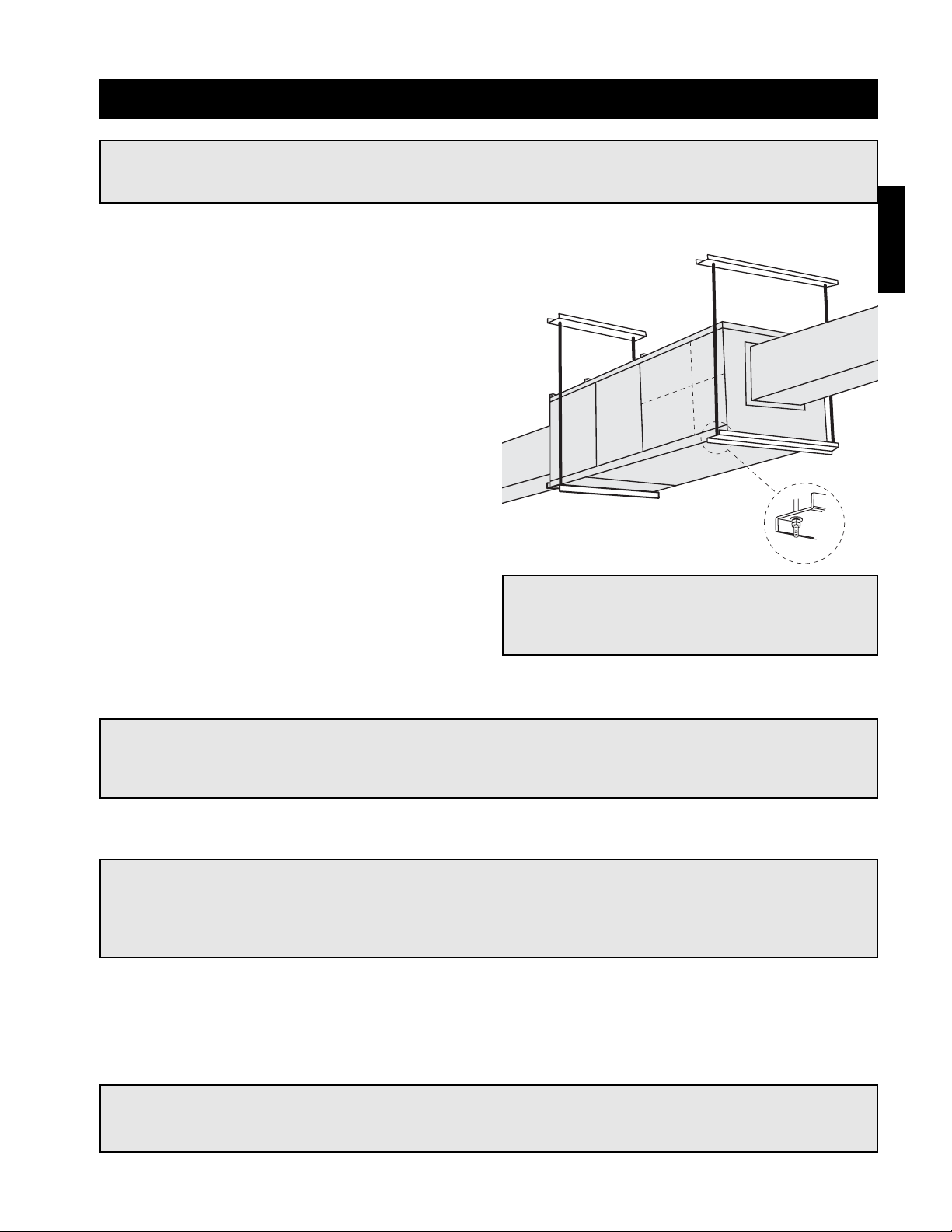
Step 2 Install Unit
Raise the unit into place.
Using two nuts per hanger, fasten the unit supports to
hangers under the unit. Appropriate unit supports,
such as the optional Greenheck hanging bracket kit
or c-channel and angle iron (supplied by others)
should be used.
Using self tapping screws, attach ductwork to unit.
In order to prevent the unit from swinging and to
provide a safe environment for service and
maintenance, additional measures must be taken to
secure the unit in all directions.
Installation - Indoor
WARNING!
All factory provided lifting lugs must be used when lifting any unit. Failure to comply with this safety
precaution could result in property damage, serious injury or death.
Step 1 Install Hangers
Install threaded hangers from ceiling supports. When
locating hangers, allow enough room to open access
panel(s). Two nuts must be used on the end of each
threaded hanger. Ceiling supports are supplied by
others.
NOTE!
Good duct practices should be followed for all ductwork. Ductwork should be installed in accordance
with SMACNA and AMCA guidelines, NFPA 96 and any local codes. Reference the CAPS submittal for
duct sizes.
NOTE!
Vent piping is supplied by others and not supplied by Greenheck.
NOTE!
Two nuts must be used on each end of each
threaded hanging rod for proper support.
Installation
NOTE!
To prevent premature heat exchanger failure, do not locate units where chlorinated, halogenated, or
acid vapors are present.
Page 4
4
Installation
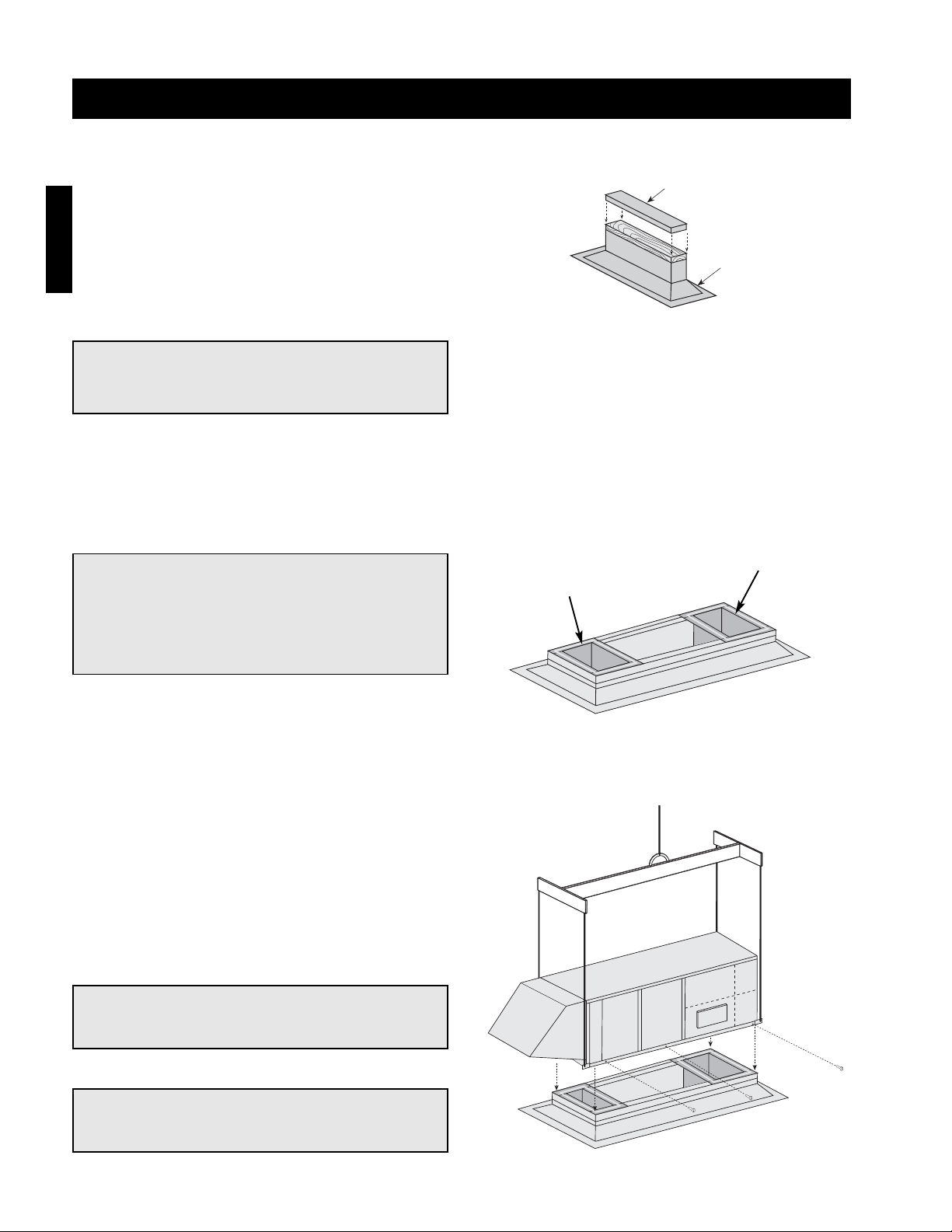
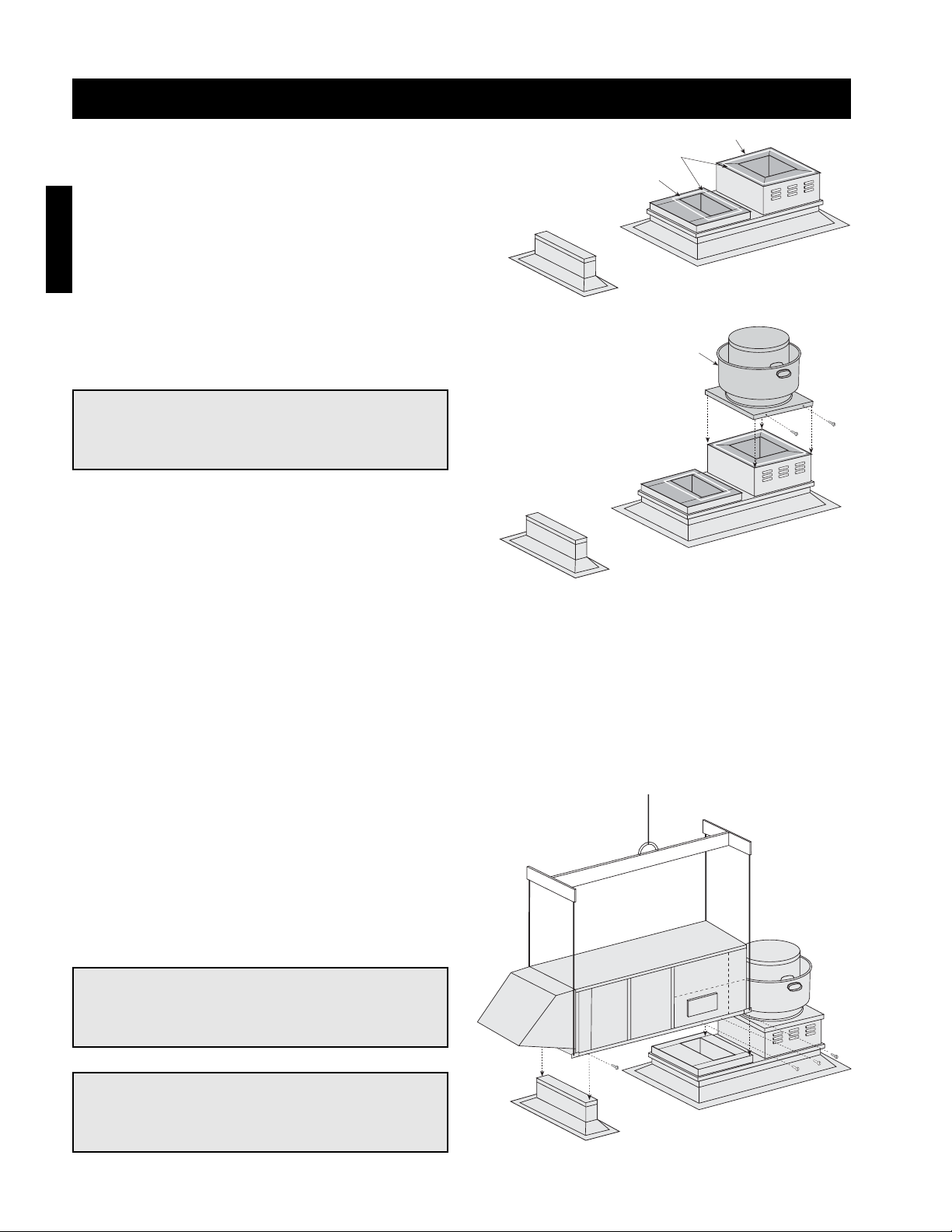
Step 1 Install Curb/Equipment
Support(s)
Position curb/equipment support(s) on the roof
(reference the CAPS submittal for placement of
curb/equipment support(s) in relation to the unit).
Verify that all unit supports are level, shim if
necessary. Attach curb to roof and flash into place.
When attaching the equipment support(s) to the roof,
remove metal cover, flash to wooden nailer and
reinstall cover.
Supply Air Duct
(Arrangement DB only)
Return Air Duct
(with mixing box only)
Metal Cover
Equipment
Support
Installation - Arrangement DB / HZ
Step 2 Install Ductwork
Good duct practices should be followed for all ductwork. All ductwork should be installed in accordance with
SMACNA and AMCA guidelines, NFPA 96 and all local codes. Reference the CAPS submittal for ductwork sizes.
Step 3 Apply Sealant
Apply an appropriate sealant around the perimeter of the curb and duct adapter(s) to isolate fan vibration and
prevent water penetration.
Step 4 Install Unit
Use a crane and a set of spreader bars hooked to the
factory lifting lugs to lift and center the unit on the
curb/equipment support(s).
Use self-tapping sheet metal screws to fasten the unit
to the curb/equipment support(s).
NOTE!
The use of a duct adapter is recommended on a
downblast (DB) arrangement to align the
ductwork with the supply unit and is only a guide
and is not support for the ductwork.
NOTE!
The use of all lifting lugs and a set of spreader
bars is mandatory when lifting the unit.
NOTE!
Be sure to complete the outdoor venting
installation instructions.
NOTE!
Refer to the outdoor venting instructions when
locating the unit.
Page 5
5
Supply
Ductwork
by Others
Exhaust
Ductwork
by Others
Installation - Arrangement DBC
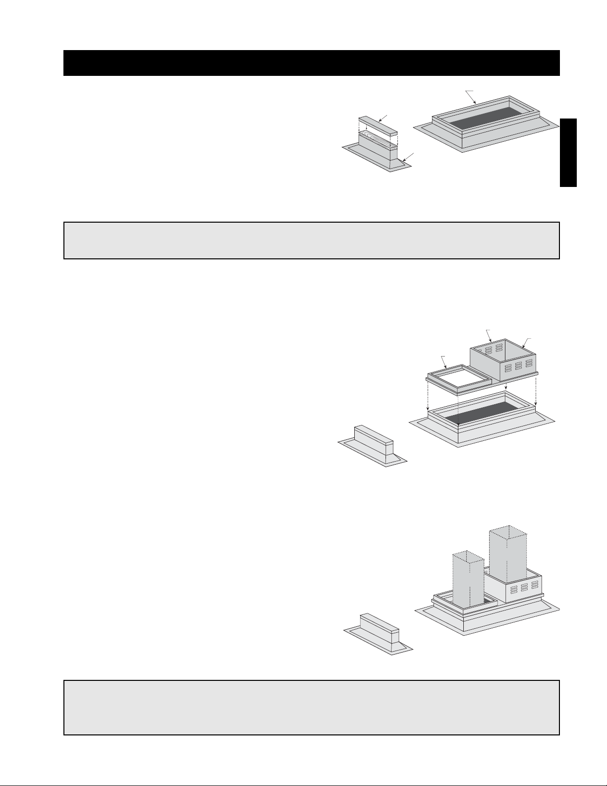
Step 1 Install Curb/Equipment
Support(s)
Position curb/equipment support(s) on the roof
(reference the CAPS submittal for placement of
curb/equipment support(s) in relation to the unit).
Verify that all unit supports are level, shim if
necessary. Attach curb to roof and flash into place.
Attach the equipment support(s) to the roof, remove
metal cover, flash to wooden nailer and reinstall
cover.
Step 2 Install Combination Extension
Install combination extension over curb. Lag into
place using wood screws. Locate the extension so
the tall, vented-side is over the exhaust opening.
NOTE!
The use of a duct adapter is recommended on a downblast (DBC) arrangement to align the ductwork
with the supply unit and is only a guide and is not support for the ductwork.
Step 3 Install Ductwork
Good duct practices should be followed for all
ductwork. All ductwork should be installed in
accordance with SMACNA and AMCA guidelines,
NFPA 96 and any local codes. Reference the CAPS
submittal for ductwork size and location.
Installation
NOTE!
Refer to the outdoor venting instructions when locating the unit.
Metal Cover
Equipment
Support
Supply
Roof Curb
Exhaust
1 inch Inside
Flange
Page 6
6
Installation
Installation - Roof Mounted Unit Arrangement DBC
Step 5 Install Exhaust Fan
Fasten exhaust fan to curb extension with selftapping sheet metal screws.
Step 6 Install Exhaust Options
Install optional Greenheck hinge kit with restraining cables and grease trap with drain connection.
Step 7 Install Supply Unit
Use a crane and a set of spreader bars hooked to the
factory lifting lugs to lift and center the unit on the
curb/equipment support(s).
Use self-tapping sheet metal screws to fasten the unit
to the curb/equipment support(s).
NOTE!
Installing the exhaust fan prior to the supply unit
will allow for easier installation of options.
NOTE!
The use of all lifting lugs and a set of spreader
bars is mandatory when lifting unit.
NOTE!
Be sure to complete the outdoor venting
installation instructions.
Step 4 Apply Sealant
Apply an appropriate sealant around the perimeter of
the curb and duct adapter(s) to isolate fan vibration
and prevent water penetration.
Supply Duct with Duct
Adapter Installed
Exhaust Duct Installed
Sealant
Model CUBE
Exhaust Fan
Page 7

7
Installation - Venting for Outdoor Units
WARNING!
Do not install units in locations where flue products can be drawn into adjacent building openings
such as windows, fresh air intakes, etc. Distance from vent terminal to adjacent public walkways,
adjacent buildings, operable windows, and building openings shall conform with the local codes. In the
absence of local codes, installation shall conform with the National Fuel Gas Code, ANSI Z223.1, or the
CAN/CGA B-149 Installation Codes.
WARNING!
The following guidelines must be followed for all outdoor units:
1. Building materials that will be affected by flue gases should be protected.
2. Maintain minimum horizontal clearance of 4 feet from electric meters, gas meters, regulators,
and relief equipment. In Canada, the minimum clearance is 6 feet.
3. The combustion blower discharge on outdoor units must be located a minimum of 42 inches
from any combustible materials.
4. Do not modify or obstruct the combustion air inlet cover or the combustion blower
weatherhood.
5. Do not add vents other than those supplied by the manufacturer.
6. During the winter, keep the unit clear of snow to prevent any blockage of the combustion
venting.
NOTE!
Clearances from combustible material for indoor units are determined by the National Fuel Gas Code
and/or other local codes.
Step 1 Follow Guidelines
All of the following guidelines must be followed when installing the unit.
Step 2 Install Stack (Optional)
Clearance may require an exhaust stack. Install an exhaust stack as needed to the exhaust connection on the
unit. Install a vent terminal on the exhaust pipe.
Installation
Page 8

8
Installation - Venting for All Indoor Units
NOTE!
The drip leg should be cleaned out periodically during the heating season.
Venting Methods
There are three venting method for indoor mounted units. Specific venting instructions are provided for each
method. Refer to the specific instructions for the venting method listed in the CAPS submittal.
The venting method options are:
• Standard Indoor Venting (uses building air for combustion, vents outdoors, one roof or wall penetration)
• Separated Combustion 2-Pipe Venting (uses outside air for combustion, vents outdoor, two exterior roof or
wall penetrations)
• Separated Combustion Concentric Venting (uses outside air for combustion, vents outdoors, one exterior roof
or wall penetration)
NOTE!
For each method, the units can be vented horizontally through an exterior wall or vertically through the
roof. Refer to the specific venting instructions for your unit. Construct the vent system as shown in
these instructions.
NOTE!
Vent piping is supplied by others and not supplied by Greenheck.
Installation
WARNING!
The following guidelines must be followed for all indoor units:
1. Installation of venting must conform with local building codes. In the absence of local codes,
installation must conform with the National Fuel Gas Code, ANSI Z223.1 or in Canada,
CAN/CGA-B149 installations codes.
2. For the exhaust pipe, use pipe approved for a category III appliance or single wall, 26 gauge or
heavier galvanized vent pipe. The piping is required to be gas tight by ANSI.
3. For the combustion air pipe on separated combustion units, sealed single-wall galvanized air
pipe is recommended.
4. The joints must be sealed with a metallic tape or silastic suitable for temperatures up to 350ºF.
5. A minimum of 12 inches of straight vent pipe is recommended after the exhaust connection and
before any elbows.
6. Vertical combustion air pipes should be fitted with a tee, drip leg and clean-out cap to prevent
any moisture in the combustion air pipe from entering the unit.
7. To reduce condensation, insulate any vent runs greater than 5 feet.
8. All vent pipe connections should be made with at least three corrosion resistant sheet metal
screws.
9. Refer to the National Fuel Gas Code for additional piping guidelines.
Page 9
9
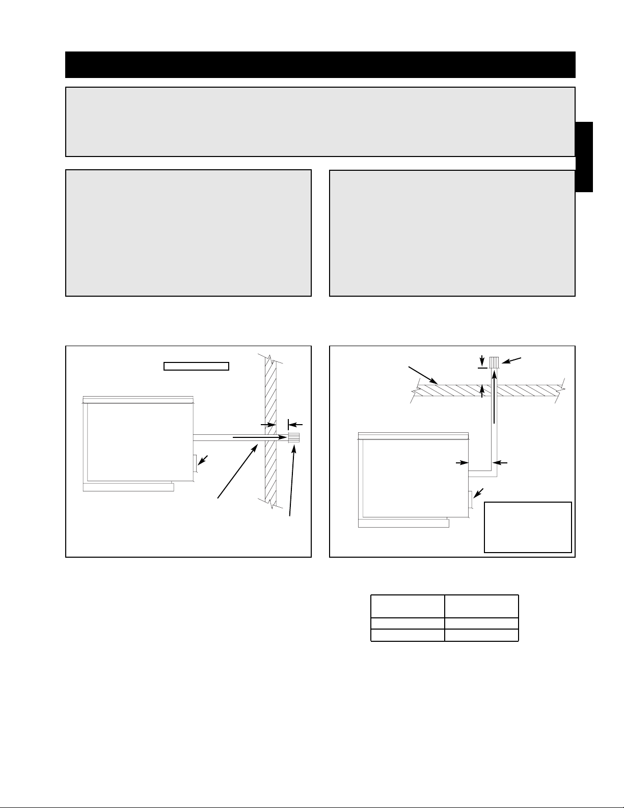
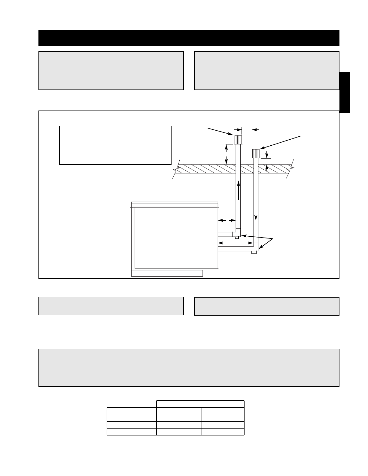
Standard Horizontal Venting
A = 12 in. minimum
A
Pitch vent pipe
downward from
furnace
1
⁄4
inches per foot
Exhaust Vent
Terminal
EXHAUST
Exterior Wall
Air Inlet
Step 1 Select Vent Pipe Size
Select the vent pipe size from the table to the right.
Use only the specified pipe size.
Step 2 Install Exhaust Vent Pipe
Install the vent pipe with minimum downward slope (from the unit) of 1⁄4 inch per foot. Securely suspend the pipe
from overhead structures at points no greater than 3 feet apart. Attach the vent terminal to the end of the
exhaust pipe.
Installation - Standard Indoor Venting
NOTE!
Standard indoor venting uses one penetration through an exterior wall or roof for venting the flue
exhaust. The combustion air is supplied from the air inside the building. Units must not be installed in
a potentially explosive, flammable, or corrosive atmosphere. To prevent premature heat exchanger
failure, do not locate units where chlorinated, halogenated, or acid vapors are present.
NOTE!
When units are installed in tightly sealed
buildings, provisions should be made to supply
adequate amount of infiltration air from the
outside. The rule of thumb is that an opening of
one square inch should be provided for every
1000 BTU per hour of input rating.
IMPORTANT!
Vent terminals must be used. Construct the vent
system as shown in drawings and reference the
tables for the correct vent pipe diameters. The
minimum vent length is 5 feet for horizontal and
10 feet for vertical. The maximum vent length is
70 feet. The total equivalent vent length must
include elbows. The equivalent length of a 4 inch
elbow is 6 feet and the equivalent length of a 6
inch elbow is 10 feet.
Standard Vertical Venting
B
A = 12 inch minimum
B = 12 inch minimum,
but should size
according to
expected snow
depth.
EXHAUST
Exhaust Vent
Terminal
Air Inlet
Roof Line
A
Furnace Exhaust Pipe
Size (MBH) Diameter
75-175 4 inches
200-400 6 inches
Installation
Page 10
10
WARNING!
The concentric venting adapter is designed for indoor installations and should never be installed on
the exterior of the building.
Installation - Concentric Venting (General)
NOTE!
Concentric venting allows the exhaust pipe and combustion air pipe to pass through a single hole in
the roof or wall of the building. A concentric venting adapter is required for concentric venting.
NOTE!
If venting vertically through the roof, refer to the vertical concentric venting instructions. If venting
horizontally through the wall, refer to the horizontal concentric venting instructions.
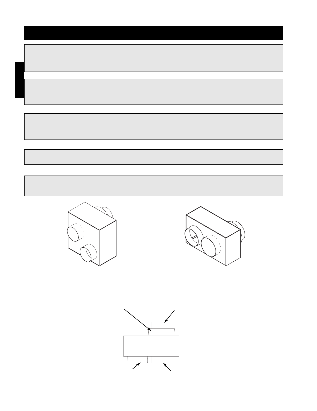
CVA-4
(4 inch Concentric Venting Adapter)
CVA-6
(6 inch Concentric Venting Adapter)
Exhaust Connection
Concentric Side
Combustion Air Connection
Concentric Side
Exhaust Connection
Non-Concentric Side
Combustion Air Connection
Non-Concentric Side
CVA
NOTE!
The exhaust pipe must terminate with the vent terminal. The combustion air pipe must terminate with
the combustion air guard (horizontal venting) or terminal (vertical venting). Both are provided in the
optional venting kit along with the concentric venting adapter (CVA).
NOTE!
Vent piping is supplied by others and not supplied by Greenheck.
Installation
Page 11
11
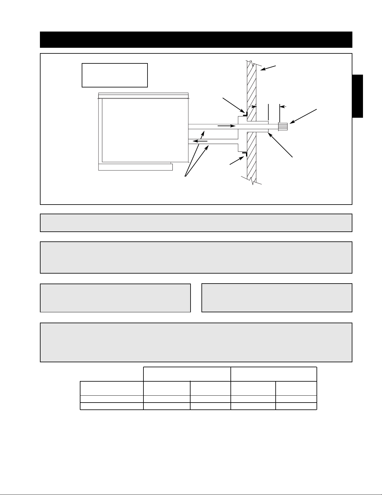
Step 1 Determine Venting Location
Determine the location of the concentric venting adapter (CVA) based on any clearances that must be maintained
(follow all codes referenced in these instructions).
Step 2 Attach Mounting Brackets
Attach field supplied, corrosion resistant mounting brackets to the CVA using corrosion resistant sheet metal
screws.
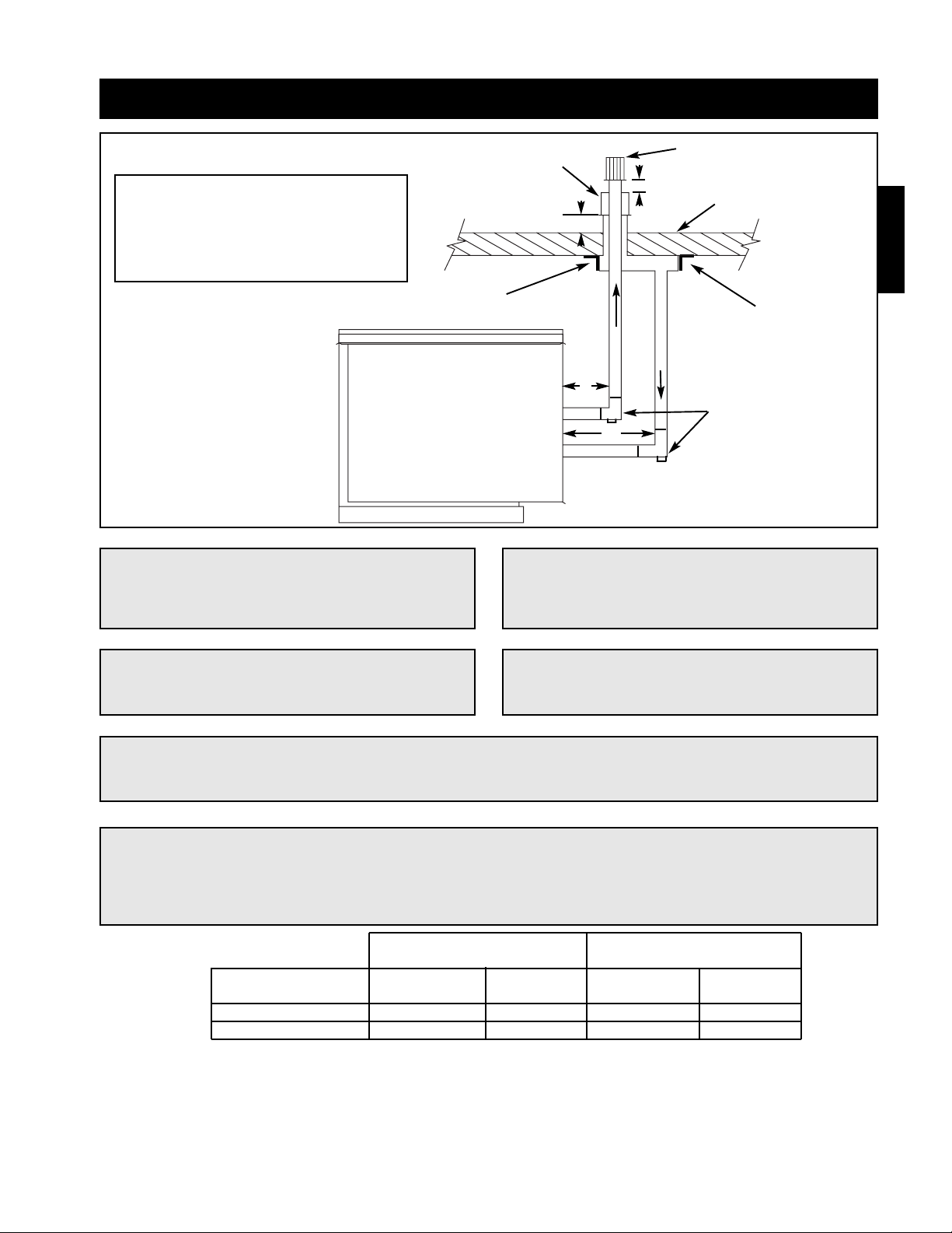
Installation - Concentric Venting (Horizontal)
EXHAUST
COMBUSTION AIR
Exterior Wall
Mounting
Bracket
Mounting
Bracket
A
B
Exhaust Pipe
Terminal
A = 2 inch minimum
B = 12 inch minimum
Combustion Air
Inlet Guard
Pitch vent pipe downward from
furnace .25 inches per foot
NOTE!
All vent piping is FIELD SUPPLIED by others and
is not supplied by Greenheck.
NOTE!
The optional venting kit includes a concentric
venting adapter (CVA), vent terminal and guard.
NOTE!
Maintain at least 12 inches from the combustion air inlet guard to the vent terminal.
NOTE!
To prevent water from running into the combustion air pipe and to allow for easy installation of the
combustion air guard, the combustion air pipe must terminate at least 2 inches from the exterior
surface of the outside wall.
Non-Concentric Concentric
Vent Connection Diameter Vent Connection Diameter
Furnace Size Exhaust Combustion Exhaust Combustion
(MBH) (Inches) Air (Inches) (Inches) Air (Inches)
75 -175 4446
200 -400 6668
Installation
IMPORTANT!
Vent terminals must be used. Construct the vent system as shown in drawings and reference the
tables for the correct vent pipe diameters. The minimum vent length is 5 feet and the maximum vent
length is 70 feet. The total equivalent vent length must include elbows. The equivalent length of a 4
inch elbow is 6 feet and the equivalent length of a 6 inch elbow is 10 feet.
Page 12
12
Step 4 Install Combustion Air Pipe
Attach a field supplied combustion air pipe to the
concentric side of the CVA.
Be sure to provide enough combustion air piping to
pass through the wall and provide the minimum
clearance of 2 inches between the combustion air
intake and the exterior surface of the outside wall.
Be sure to maintain the minimum clearance of 12
inches between the exhaust pipe termination and the
combustion air intake.
Step 5 Install CVA Assembly
Place the entire CVA assembly through the wall and verify that all minimum clearance requirements as specified
in these instructions are met. Secure the CVA assembly to the wall with corrosion resistant sheet metal screws
through the mounting brackets.
Step 6 Attach CVA Assembly to Unit
Attach the exhaust pipe to the unit’s combustion exhaust. Using an additional combustion air pipe, connect the
unit’s combustion air supply intake to the combustion air connection on the CVA.
Step 8 Seal Opening
Seal the opening between the wall and the air intake pipe using an appropriate method.
Step 7 Install Combustion Air Inlet Guard and Exhaust Vent Terminal
Slide the combustion air inlet guard over the exhaust pipe and fasten it to the combustion air pipe. Attach the
exhaust vent terminal to the discharge end of the exhaust piping on the outside of the building.
Step 3 Install Exhaust Pipe
Slide the exhaust pipe through the CVA.
Be sure to provide enough exhaust piping to pass
through the wall and provide the minimum clearance
of 12 inches between the exhaust pipe termination
and the combustion air intake.
With all required clearances satisfied, attach the
exhaust pipe to the CVA.
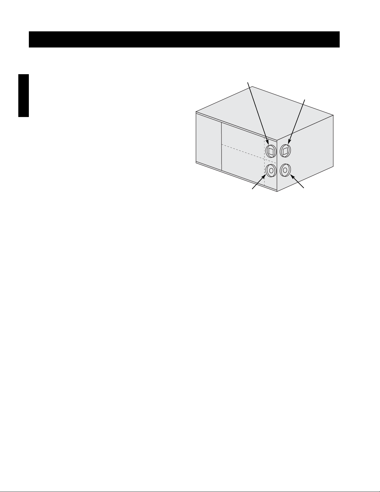
Installation - Concentric Venting (Horizontal)
Exhaust
Connection
(Model IG)
Exhaust
Connection
(Model IGX)
Combustion Air
Connection
(Model IG)
Combustion Air
Connection
(Model IGX)
Installation
Intake End
Discharge
End
Page 13
13
Installation - Concentric Venting (Vertical)
NOTE!
All vent piping is FIELD SUPPLIED by others.
Exhaust Vent Terminal
Combustion Air
Inlet Terminal
A
C
C
B
Roofline
EXHAUST
COMBUSTION AIR
Tee with drip leg and
cleanout cap
A = 12 inch minimum, but should size
according to expected snow depth.
B = 12 inch minimum
C = 12 inch minimum
NOTE!
Maintain at least 12 inches of clearance between
the top of the combustion air inlet terminals and
the bottom of the exhaust terminal.
NOTE!
A tee with clean-out must be provided on the combustion air and exhaust pipe to prevent debris from
entering the heat exchanger.
NOTE!
The bottom of the combustion air intake pipe
must terminate above the snow line, or at least
12 inches above the roof, whichever is greater.
Mounting
Bracket
Mounting
Bracket
Step 1 Determine Venting Location
Determine the location of the concentric venting adapter (CVA) based on any clearances that must be maintained
(follow all codes referenced in these instructions).
Step 2 Attach Mounting Brackets
Attach field supplied corrosion resistant mounting brackets to the CVA.
NOTE!
The optional venting kit includes a concentric
venting adapter (CVA), and two terminals.
Installation
IMPORTANT!
Vent terminals must be used. Construct the vent system as shown in drawings and reference the
tables for the correct vent pipe diameters. The minimum vent length is 10 feet and the maximum vent
length is 70 feet. The total equivalent vent length must include elbows. The equivalent length of a
4 inch elbow is 6 feet and the equivalent length of a 6 inch elbow is 10 feet.
Non-Concentric Concentric
Vent Connection Diameter Vent Connection Diameter
Furnace Size Exhaust Combustion Exhaust Combustion
(MBH) (inches) Air (inches) (inches) Air (Inches)
75 -175 4446
200 -400 6668
Page 14

14
Installation - Concentric Venting (Vertical)
Step 3 Install Exhaust Pipe
Slide the exhaust pipe through the CVA.
Be sure to provide enough exhaust piping to pass
through the roof and provide the minimum clearance
of 12 inches between the exhaust pipe termination
and the combustion air intake.
With all required clearances satisfied, attach the
exhaust pipe to the CVA.
Step 4 Install Combustion Air Pipe
Attach a field supplied combustion air pipe to the
concentric side of the CVA. Be sure to provide enough
combustion air piping to pass through the roof and
provide the minimum clearance of 12 inches between
the combustion air intake and the exterior surface of
the roof. This clearance may need to be increased to
allow for snow accumulation. Be sure to maintain the
minimum clearance of 12 inches between the exhaust
pipe termination and the combustion air intake.
Step 5 Install CVA Assembly
Place the entire CVA assembly through the roof and verify that all minimum clearance requirements as specified
in these instructions are met. Secure the CVA assembly to the ceiling with corrosion resistant sheet metal screws
through the mounting brackets.
Step 6 Attach CVA Assembly to Unit
Attach the exhaust pipe to the unit’s combustion exhaust. Using an additional combustion air pipe, connect the
unit’s combustion air supply intake to the combustion air connection on the CVA. Be sure to include the required
tee’s with drip legs and clean outs.
Step 8 Seal Opening
Seal the opening between the roof and the air intake pipe using an appropriate method.
Step 7 Install Terminals
Slide the combustion air terminal over the vent pipe and fasten it to the combustion air pipe. Attach the exhaust
vent terminal to the discharge end of the exhaust piping.
Installation
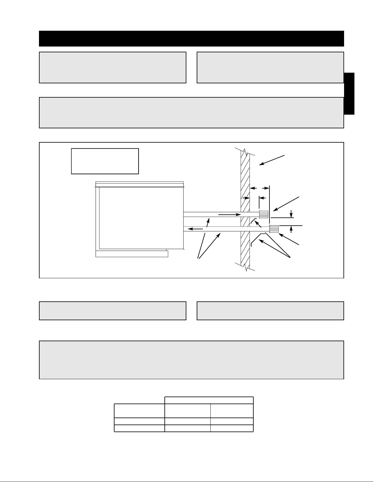
Exhaust
Connection
(Model IG)
Exhaust
Connection
(Model IGX)
Combustion Air
Connection
(Model IG)
Combustion Air
Connection
(Model IGX)
Intake End
Discharge
End
Page 15
15
Exterior Wall
B
A
EXHAUST
COMBUSTION AIR
Pitch vent pipe downward from
furnace 1⁄4 inches per foot
C
Field Supplied
Support Brackets
A = 12 inch minimum
B = 24 inch minimum
C = 12 inch minimum
Exhaust Vent
Terminal
Combustion Air
Inlet Terminal
Installation - Two Pipe Venting (Horizontal)
NOTE!
All vent piping is FIELD SUPPLIED by others.
NOTE!
Maintain at least 12 inches of clearance between
the exhaust pipe termination and the exterior
surface of the exterior wall.
NOTE!
The combustion air pipe must be a minimum of
12 inches from the exhaust pipe and 24 inches
from the exterior surface of the outside wall.
NOTE!
Optional venting kit includes two vent terminals.
Installation
NOTE!
A minimum of 1 inch and a maximum of 48 inch of building wall thickness is required for separated
combustion vent pipe.
IMPORTANT!
Vent terminals must be used. Construct the vent system as shown in drawings and reference the
tables for the correct vent pipe diameters. The minimum vent length is 5 feet and the maximum vent
length is 50 feet. The total equivalent vent length must include elbows. The equivalent length of a
4 inch elbow is 6 feet and the equivalent length of a 6 inch elbow is 10 feet.
Vent Connection Diameter
Furnace Size Exhaust Combustion
(MBH) (Inches) Air (Inches)
75 - 175 4 4
200 - 400 6 6
Page 16
16
Step 1 Install Exhaust Pipe
Run an exhaust pipe from the unit’s combustion
exhaust through the exterior wall to the outdoors. The
exhaust pipe must terminate at least 12 inches from
the outside surface of the outside wall. Attach exhaust
vent terminal to the end of the exhaust pipe. Using
field supplied mounting brackets, support the exhaust
pipe as needed.
Step 3 Seal Wall Openings
Using an appropriate method, seal the wall openings around the piping.
Step 2 Install Combustion Air Pipe
Run a combustion air pipe from the unit’s combustion
air intake through the exterior wall to the outdoors.
The combustion air pipe must terminate at least 12
inches from the combustion vent pipe and 24 inches
from the exterior surface of the outside wall. Attach
the combustion air inlet guard to the end of the
combustion air pipe. Using field supplied mounting
brackets, support the combustion air pipe as needed.
Installation - Two Pipe Venting (Horizontal)
Installation
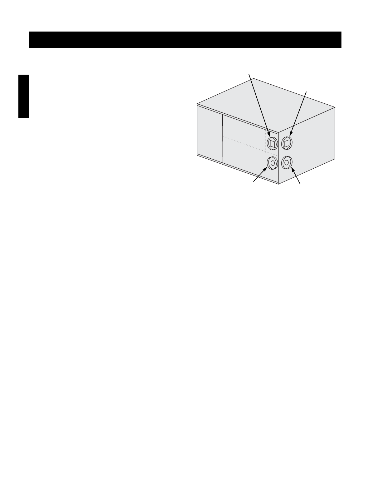
Exhaust
Connection
(Model IG)
Exhaust
Connection
(Model IGX)
Combustion Air
Connection
(Model IG)
Combustion Air
Connection
(Model IGX)
Intake End
Discharge
End
Page 17
17
C
D
D
B
A
A = 12 inch minimum, but should size
according to expected snow depth.
B = 24 inch minimum
C = 12 inch minimum
D = 12 inch minimum
EXHAUST
COMBUSTION AIR
Tee with drip leg and
clean-out cap.
Combustion Air
Inlet Terminal
Exhaust Vent
Terminal
Installation - Two Pipe Venting (Vertical)
NOTE!
The combustion air pipe must terminate at least
12 inches above the roof. This clearance may
need to be increased to accommodate for snow
accumulation.
NOTE!
The exhaust must terminate at least 12 inches
above and 12 inches horizontally from the
combustion air inlet.
NOTE!
All vent piping is FIELD SUPPLIED by others.
NOTE!
The optional vent kit includes two terminals.
Installation
IMPORTANT!
Vent terminals must be used. Construct the vent system as shown in drawings and reference the
tables for the correct vent pipe diameters. The minimum vent length is 10 feet and the maximum vent
length is 70 feet. The total equivalent vent length must include elbows. The equivalent length of a
4 inch elbow is 6 feet and the equivalent length of a 6 inch elbow is 10 feet.
Vent Connection Diameter
Furnace Size Exhaust Combustion
(MBH) (Inches) Air (Inches)
75 - 175 4 4
200 - 400 6 6
Page 18

18
Installation
Step 1 Install Exhaust Pipe
Run an exhaust pipe from the unit’s combustion
exhaust through the roof to the outdoors. The exhaust
pipe must terminate at least 12 inches above the
outside surface of the roof. This clearance may need
to be increased to accommodate snow accumulation.
Attach the exhaust vent terminal to the end of the
exhaust pipe.
Step 3 Seal Roof Penetration
Using an appropriate method, seal the roof openings around the vent pipes.
Step 2 Install Combustion Air Pipe
Run a combustion air pipe from the unit’s combustion
air intake through the roof to the outdoors. The
combustion air pipe must terminate at least 12 inches
horizontally and vertically from the combustion
exhaust pipe and at least 24 inches from the exterior
surface of the roof. These clearances may need to be
increased to accommodate for expected snow
accumulation. Attach the combustion air terminal to
the end of the combustion air pipe.
Installation - Two Pipe Venting (Vertical)
Exhaust
Connection
(Model IG)
Exhaust
Connection
(Model IGX)
Combustion Air
Connection
(Model IG)
Combustion Air
Connection
(Model IGX)
Intake End
Discharge
End
Page 19
19
Installation - Electrical Wiring
CAUTION!
If replacement wire is required, it must have a
temperature rating of at least 105°C, except for
energy cut-off or sensor lead wire which must be
rated to 150°C.
CAUTION!
Any wiring deviations may result in personal injury or property damage. Greenheck is not responsible
for any damage to, or failure of the unit caused by incorrect final wiring.
DANGER!
High voltage electrical input is needed for this
equipment. This work should be performed by a
qualified electrician.
IMPORTANT!
All wiring should be done in accordance with the
latest edition of the National Electric Code
ANSI/NFPA-70 and any local codes that may
apply. In Canada, wiring should be done in
accordance with the Canadian Electrical Code.
IMPORTANT!
The equipment must be properly grounded.
Any wiring running through the unit in the
airstream must be protected by metal conduit,
metal clad cable or raceways.
IMPORTANT!
Before connecting power to the unit, read and understand the following instructions and wiring
diagrams. Complete wiring diagrams are attached on the inside of the control center door(s).
IMPORTANT!
Greenheck’s standard control voltage is 24 VAC.
Control wire resistance should not exceed 0.75 ohms (approximately 285 feet total length for 14 gauge
wire; 455 feet total length for 12 gauge wire). If the resistance exceeds 0.75 ohms an industrial-style,
plug-in relay should be wired in place of the remote switch. The relay must be rated for at least 5
amps and have a 24 VAC coil. Failure to comply with these guidelines may cause motor starters to
chatter or not pull in, resulting in contactor failures and/or motor failures.
Step 3 Connect the Main Power
Connect the main power lines to the disconnect switch and main grounding lug(s). Torque field connections to
20 in-lbs. See the blower control center layout in the reference section for main disconnect and grounding lug(s)
locations.
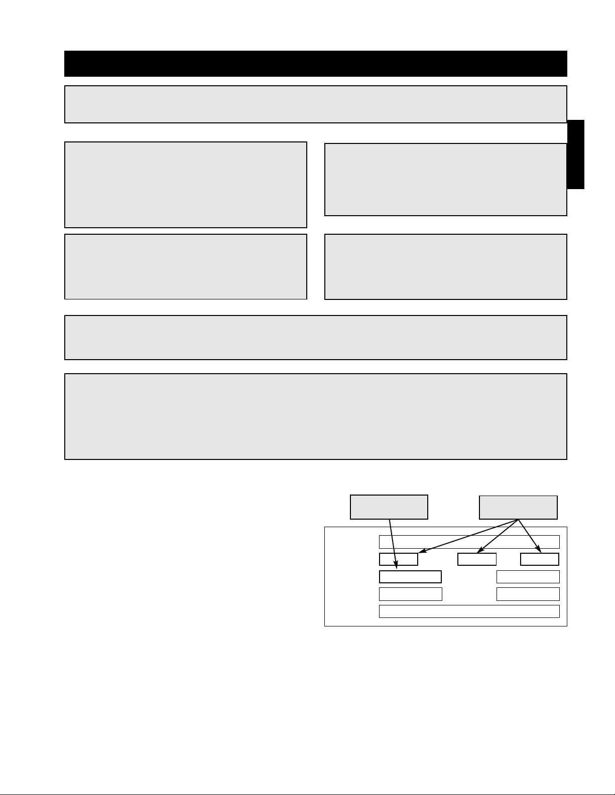
Step 1 Determine the Size of the Main
Power Lines
The unit nameplate states the voltage and the unit’s
total amps. The main power lines to the unit should
be sized accordingly.
Step 2 Provide the Opening(s) for the
Electrical Connections
Electrical openings vary by unit size and arrangement
and are field supplied.
MODEL
VOLTS
SUP HP
MARK
AMPS
HTZ PH
S/N
EXH HP
Voltage, Hertz,
and Phase
Unit’s Total
Amps
Installation
Page 20
20
Installation
Step 5 Wire the Accessories
Reference the ladder diagram in the control center for
correct wiring of the following accessories:
Step 6 Wire Optional Evaporative Cooler
Reference the ladder diagram on the inside of the control center door for correct wiring of the pump and the
optional auto-drain and flush. If the Water Wizard was selected, the temperature sensor may need to be wired,
refer to the Water Wizard start-up.
Step 7 Install Optional Economizer Sensors
All economizer options (EC) require an outdoor air temperature or enthalpy sensor to be field installed inside of
the weatherhood and field wired to terminals SO+ and SO- on the economizer.
Economizer options EC-3 and EC-4 require an outdoor air temperature or enthalpy sensor to be field installed in
the return air duct and field wired to terminals SR+ and SR- on the economizer.
The sensors are provided by the factory and ship with the unit.
NOTE!
Large evaporative coolers may require a separate power supply.
NOTE!
The TSCP and KSCP remote panels have number-to-number wiring.
NOTE!
Wiring to the Selectrastat or room override
should be in separate conduit or run with
shielded cable.
Installation - Electrical Wiring
• Selectrastat
• Room Override
• Blower Switch
• Heat Switch
• Indicating Lights
• Dirty Filter Indicator
• TSCP
• KSCP
• Mixing Box Actuator
• Room Stat
Step 4 Wire the Convenience Outlet (Optional)
The optional convenience outlet requires a separate 115V power supply circuit with short circuit protection by
others.
Page 21
21
Installation
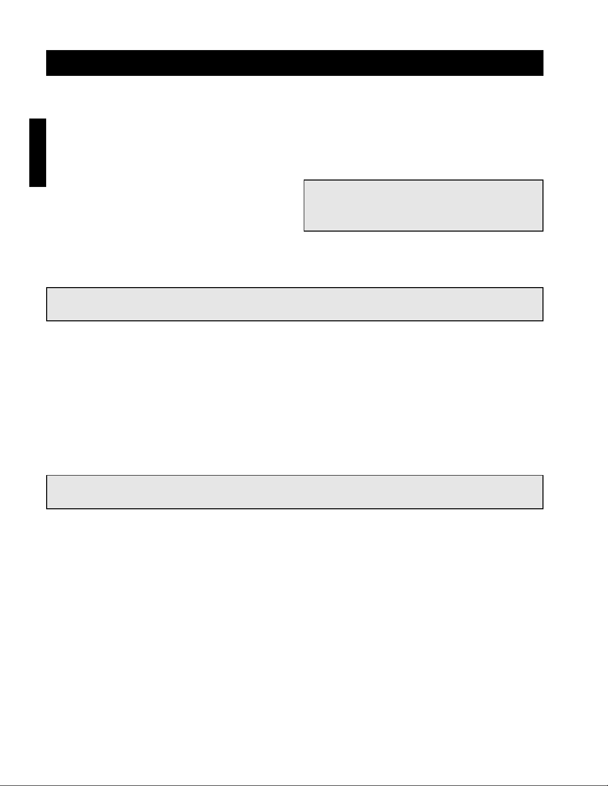
70
65
75
80
85
90
60
55
(OPTIONAL)
BLOWER
DIRTY FILTERS
MAIN VALVES
ALARM
EXHAUST
SUPPLY
HEAT
(OPTIONAL)
GREENHECK
®
PHOTOHELIC
Step 9 Check Recirculation / VAV Operation (Optional)
Two Position Damper Control
Confirm that the return damper adjusts to each position of the recirculating switch. The damper actuator may
take a few minutes to open or close.
Two Speed
Confirm that the fan speed adjusts to each position of the fan speed switch.
Potentiometer Control
To test potentiometer operation, turn the potentiometer to the two extremes. With recirculation, confirm that the
return air damper fully opens and fully closes. The damper actuator may take a few minutes to open or close.
With variable volume, make sure the fan goes to maximum and minimum speed.
Building Pressure Control
See page 31 for building pressure set-up and operation check.
Step 8 Install Discharge Air Sensor (Optional)
For units with 8:1, 16:1 or 24:1 staged turndown, install the discharge air sensor at least three duct diameters
downstream of the heat exchanger. The discharge air sensor can be found in the unit’s control center.
Step 10 Install DDC Interface (Optional)
Some units may use an external signal from a building management system to control the dampers and/or
discharge air temperature. Reference the unit ladder diagram for the correct wiring.
Installation - Electrical Wiring
NOTE!
For maintenance issues associated with variable frequency drives, consult the drive’s manual supplied
with the unit. The drives are programmed at the factory and should not need any adjustment during
installation or start-up. For kitchen applications, the drive may be located in the kitchen or in the unit.
70
65
75
80
85
90
60
55
(OPTIONAL
)
BLOWE
R
DIRTY FILTERS
MAIN VALVES
ALARM
EXHAUST
SUPPLY
HEA
T
(OPTIONAL
)
GREENHE
CK
®
70
65
75
80
85
90
60
55
GREENHECK
®
(OPTIONAL)
BLOWER
DIRTY FILTERS
MAIN VALVES
ALARM
RECIRCULATION
EXHAUST
SUPPLY
HEAT
(OPTIONAL)
2-Position Damper ControlPotentiometer ControlPhotohelic Control
NOTE!
Blower start-up (S-1), steps 1-4 should be performed before the blower is run.
Page 22
22
Installation - Gas Piping
IMPORTANT!
All gas piping must be installed in accordance with the latest edition of the National Fuel Gas Code
ANSI/Z223.1 and any local codes that may apply. In Canada, the equipment shall be installed in
accordance with the Installation Code for Gas Burning Appliances and Equipment (CGA B149) and
Provincial Regulations for the class. Authorities having jurisdiction should be consulted before
installations are made.
WARNING!
When leak testing pressures above 14 in. wc
(1⁄2 psi), close the field installed shutoff valve,
disconnect the furnace and gas train from the
gas supply line and plug the supply line before
testing.
WARNING!
When leak testing pressures equal to or less
than 14 in. wc (1⁄2 psi), first close the field-
installed shutoff valve to isolate the unit from
the gas supply line.
NOTE!
Furnaces have a single 3⁄4 inch connection.
NOTE!
When connecting the gas supply, the length of the run must be considered in determining the pipe
size to avoid excessive pressure drop. Refer to a Gas Engineer’s Handbook for gas pipe capacities.
IMPORTANT!
All piping should be clean and free of any foreign
material. Foreign material entering the gas train
can cause damage.
“W.C.
“W.C.
“W.C.
F
PSI
“W.C.
“W.C.
MAX BTU/HR
BTU/H MAX
NORMAL MANIFOLD
PRESSURE
PRESSION D’ADMISSION
NORMALE
MIN GAS
PRESSURE
PRESSION DE GAZ
TYPE OF GAS
NATURE DU GAZ
MIN BTU/HR
BTU/H MIN
MIN GAS PRESSURE
FOR MAX OUTPUT
PRESSION DE GAZ MIN
POUR PUISSANCE MAX
MAX GAS
PRESSURE
PRESSION DE GAZ
MAX
DESIGN ∆T
∆T NORMALE
EQUIPPED FOR
CONCU POUR
SCFM
“W.C.
EXTERNAL STATIC PRESSURE
PRESSION STATIQUE EXTERIEURE
AGAINST
CONTE
Minimum and
maximum gas
pressures
Minimum gas
pressure for
maximum output
Type of Gas
IMPORTANT!
Do NOT connect the unit to gas types other than
what is specified and do NOT connect the unit to
gas pressures that are outside of the pressure
range shown on the label.
Step 1 Determine the Supply Gas Requirements
The unit’s nameplate states the requirements for the gas being supplied to the unit.
Installation
Page 23
23
Installation
Installation - Gas Piping
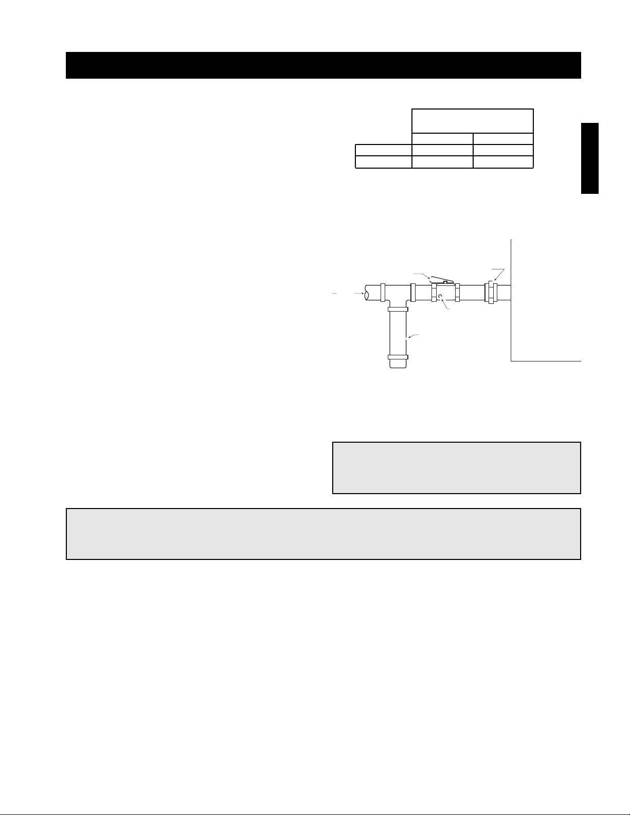
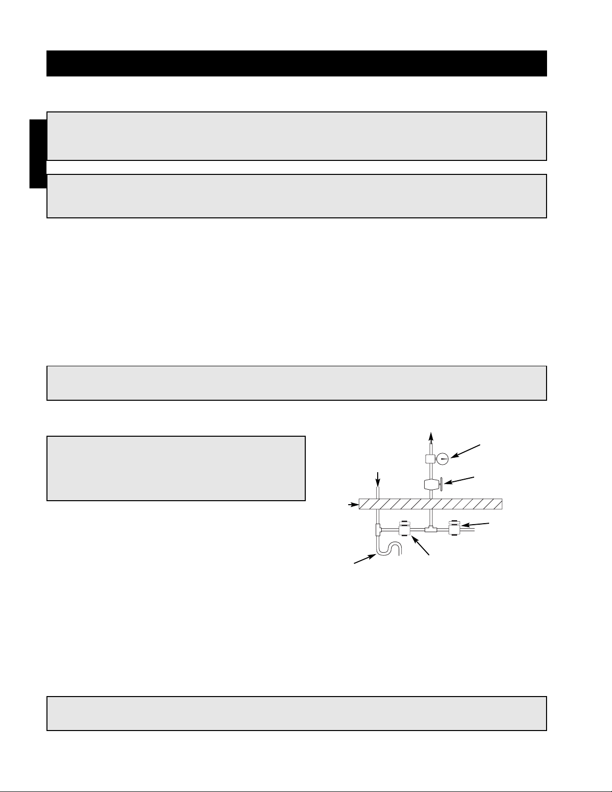
Step 3 Connect the Supply Gas Line
A manual shut off valve (gas cock), 1/8 inch plugged
test port and 6 inch drip leg must be installed prior to
the gas train. The valve and the test port must be
accessible for the connection of a test gauge. Supply
gas connections must be made by a qualified installer
and are not furnished by Greenheck.
Step 2 Install Additional Regulator if
Required
When the supply gas pressure exceeds the maximum
gas pressure shown on the unit’s nameplate, an
additional regulator (by others) is required to reduce
the pressure. The regulator must have a listed leak
limiting device or it must be vented to the outdoors.
From
Gas
Supply
Gas Cock
1/8 in. Plugged Tap
6 in. Trap
Ground Joint Union
Step 4 Test the System for Leaks
Check both the supply lines and the factory piping for
leaks. Apply a soap and water solution to all piping
and watch for bubbling which indicates a leak.
WARNING!
The factory piping has been checked for leaks, but should be rechecked due to shipping and
installation.
WARNING!
NEVER test for a gas leak with an open flame.
Supply Gas Pressure
Range (in. wc.)
Minimum Maximum
Natural 6 14
LP 10 14
Make-Up
Air Unit
Page 24
24
Installation - Evaporative Cooling Piping (Optional)
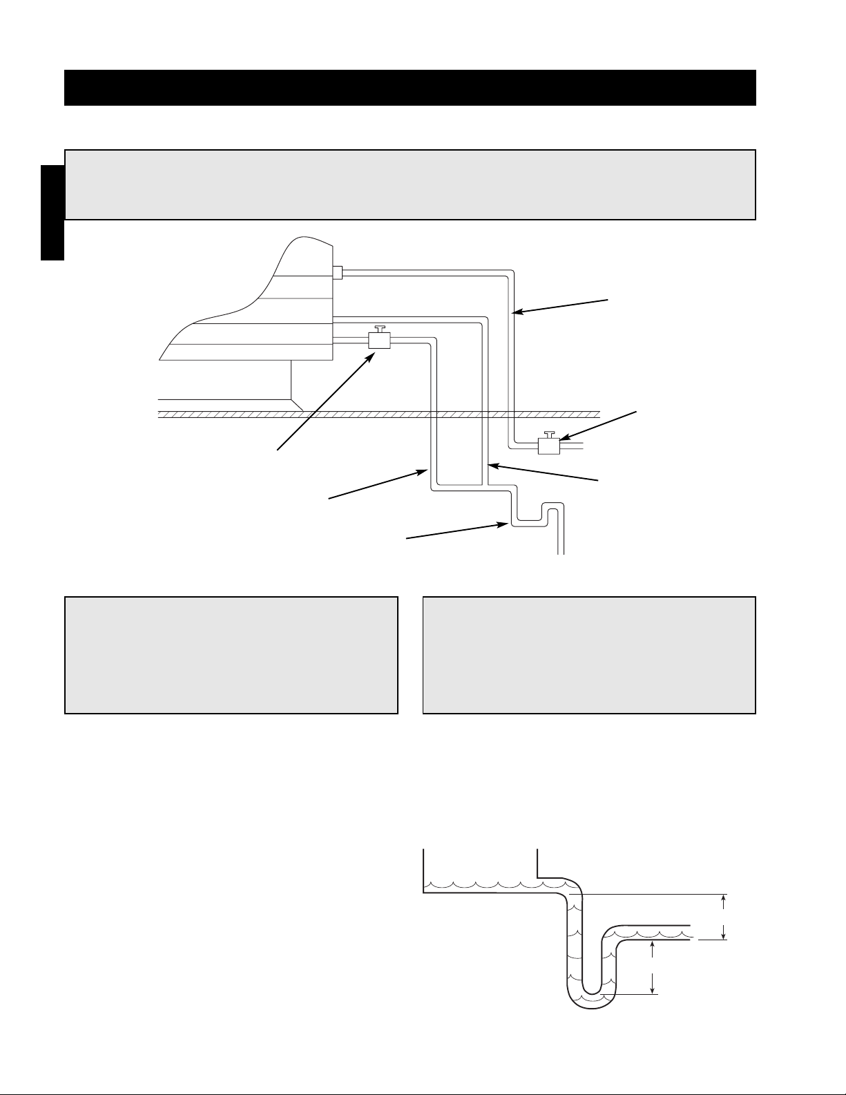
Evaporative Cooling with Bleed-Off
IMPORTANT!
The supply line should be of adequate size and
pressure to resupply the amount of water lost
due to bleed-off and evaporation. The drain line
should be the same size or larger than the
supply line.
NOTE!
The following instructions are provided for evaporative coolers with bleed-off only.
Additional instructions are provided for evaporative coolers equipped with the Water Wizard
or auto-drain and fill.
Step 1 Install the Water Supply Line
Connect the water supply line to the float valve in the evaporative cooling unit. Install a manual shutoff valve in
the supply line as shown above.
Step 2 Install the Drain Line
Connect an unobstructed drain line with a manual
shut-off valve from the sump drain to the main drain
line as shown above. A trap should be used to
prevent sewer gas from being drawn into the unit.
6 in. min.
6 in. min.
Supply
Line
Overflow
Trap
Drain Line
Valve
Drain
Line
Supply Line
Valve
CAUTION!
All solenoids, valves and traps must be installed
below the roof to protect the water supply line
from freezing. If they cannot be installed below
the roof, an alternative method must be used to
protect the lines from freezing
Installation
Page 25
25
Installation - Evaporative Cooling Piping (Optional)
IMPORTANT!
The supply line should be of adequate size and pressure to resupply the amount of water lost due to
bleed-off and evaporation. The drain line should be the same size or larger than the supply line.
CAUTION!
All solenoids, valves and traps must be installed
below the roof to protect the water supply line
from freezing. If they cannot be installed below
the roof, an alternative method must be used to
protect the lines from freezing
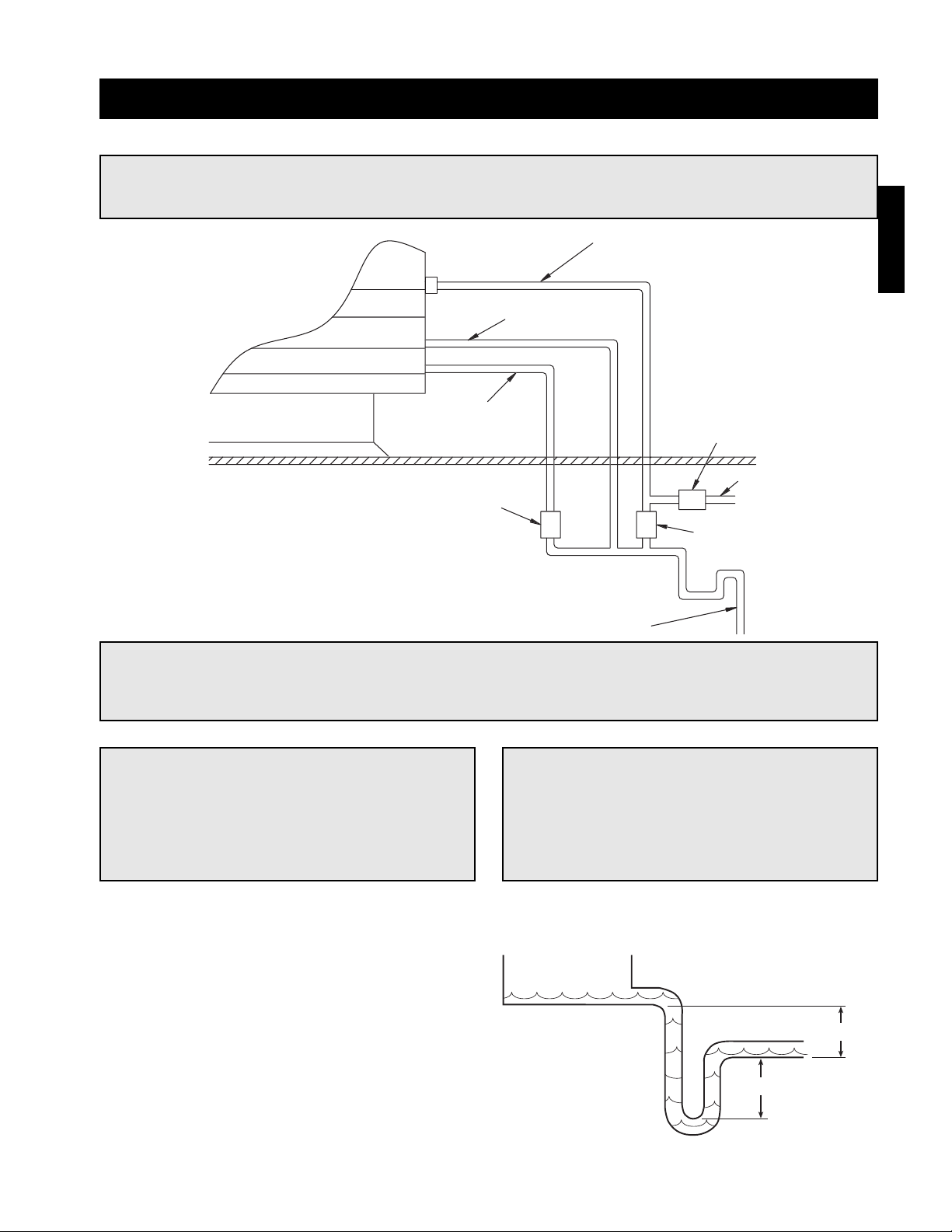
IMPORTANT!
The supply solenoid (Valve A) is NOT the same as
the drain solenoids (Valve B and Valve C). Make
sure to use the proper solenoid for each
location. Check your local code requirements for
proper installation of this type of system.
Step 1 Install the Water Supply Line
Connect the water supply line to the float valve in the
unit. Install the
1
⁄2 inch normally closed solenoid (Valve
A) in the supply line as shown above. Install the 1⁄4
inch normally open solenoid (Valve B) between the
supply line and the drain line as shown above.
Step 2 Install the Drain Line
Connect an unobstructed drain line to the sump drain.
Install the
3
⁄4 inch normally open solenoid (Valve C)
between the sump drain connection and the drain
line. A trap should be used to prevent sewer gas from
being drawn into the unit.
Evaporative Cooling with Auto Drain and Fill
g
S
n
S
e
w
Sump
n
e
A
y
B
C
6 in. min.
6 in. min.
Installation
NOTE!
The following instructions are provided for evaporative coolers with auto-drain and fill only. Additional
instructions are provided for evaporative coolers equipped with the Water Wizard or bleed-off.
Evaporative Coolin
ectio
Sump Overflo
Drai
Valve
upply Lin
Valve
To Water Suppl
Valve
Drain Lin
Page 26
26
Evaporative Cooling with the Water Wizard
Installation - Water Wizard (Optional)
Step 3 Wire the Solenoid(s)
Wire the supply solenoid to terminals X and 25 in the
control center. Wire the drain solenoid to terminals X and
26 in the control center.
Step 4 Wire the Temperature Sensor
If the evaporative cooler shipped separate from the unit, the temperature sensor must be wired. The sensor wire
is bundled inside the discharge end of the evaporative cooler. Wire the sensor wire to terminals AI2 and AIC on
the terminal strip in the unit’s control center.
Step 1 Install Supply Line/Solenoid
Connect the water supply line to the manual supply valve in the unit. Install the supply solenoid in the supply
line, upstream of the manual supply valve and below the roofline.
Step 2 Install Drain Line/Solenoid
Connect the drain line to the supply line between the manual supply valve and the supply solenoid. Install a
drain solenoid in the drain line, below the roof line.
CAUTION!
Any wiring deviations may result in personal injury
or property damage. Greenheck is not responsible
for any damage to, or failure of the unit caused by
incorrect final wiring.
NOTE!
The Water Wizard start-up must be completed for proper performance.
NOTE!
Solenoid(s) may be provided by Greenheck (if ordered) or by others.
WARNING!
Disconnect and lock-out all power and gas before performing any maintenance or service to the unit.
Failure to do so could result in serious injury or death and damage to equipment.
Drain Solenoid
Supply
Solenoid
Manual
Supply Valve
Pressure
Gauge
To Media
Sump
Drain
Roof
Line
Trap
Installation
NOTE!
The following instructions are provided for evaporative coolers equipped with the Water Wizard only.
Additional instructions are provided for evaporative coolers equipped with the auto-drain and fill or
bleed-off.
Page 27
27
Installation - Direct Expansion Coil Piping (Optional)
IMPORTANT!
Guidelines for the installation of direct expansion cooling coils have been provided to ensure proper
performance and longevity of the coils. These are general guidelines that may have to be tailored to
meet the specific requirements of any one job. As always, a qualified party or individual should
perform the installation and maintenance of any coil. Protective equipment such as safety glasses,
steel toe boots and gloves are recommended during the installation and maintenance of the coil.
IMPORTANT!
All field brazing and welding should be
performed using high quality materials and an
inert gas purge (such as nitrogen) to reduce
oxidation of the internal surface of the coil.
IMPORTANT!
All field piping must be self-supporting and
flexible enough to allow for the thermal
expansion of the coil.
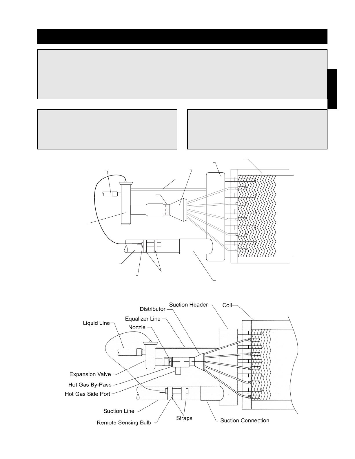
General
Hot Gas Bypass
(by others)
(by others)
Installation
Liquid Line
Equalizer Line
Nozzle
Expansion Valve
Suction Line
Remote Sensing Bulb
Suction Header
Distributor
Straps
Coil
Suction Connection
Page 28
28
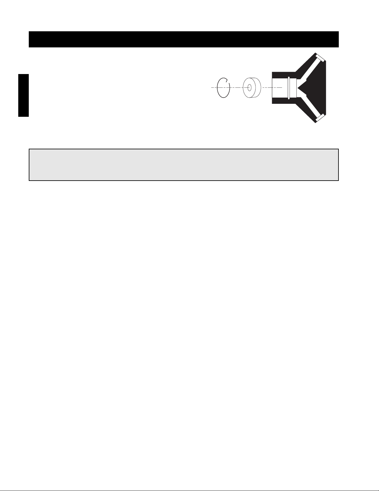
Step 1 Verify Nozzle Placement
Inspect the refrigerant distributor and verify that the
nozzle is in place. The nozzle is generally held in
place by a retaining ring or is an integral part of the
distributor itself.
Step 2 Install the Optional Hot Gas Bypass Kit (By Others)
If a hot gas bypass kit was ordered with the coil, install it now. Consult the IOM from the bypass kit supplier for
complete installation instructions. Align the side port with the hot gas line prior to brazing into place.
Step 3 Install Suction Line
Install a suction line from the compressor to the suction connection.
Step 4 Install the Thermal Expansion Valve (TEV) (By Others)
Follow the TEV manufacturer’s recommendations for installation to avoid damaging the valve. If the valve is
externally equalized, use a tubing cutter to cut off the plugged end of the factory installed equalizer line. Use a
de-burring tool to remove any loose metal from the equalizer line and attach it to the TEV. If the valve is
internally equalized, the factory installed equalizer line can be left as is.
Step 5 Mount the Remote Sensing Bulb (By Others)
The expansion valve’s remote sensing bulb should be securely strapped to the horizontal run of the suction line
at the 3 or 9 o’clock position and insulated.
Installation - Direct Expansion Coil Piping (Optional)
NOTE!
If a hot gas bypass kit was ordered, the nozzle will not be located in the distributor, it will be located in
the hot gas bypass kit.
Installation
Retainer
Ring
Nozzle Distributor
Page 29

29
Step 7 Evacuate and Charge the Coil
Use a vacuum pump to evacuate the coil and any interconnecting piping that has been open to the atmosphere.
Measure the vacuum in the piping using a micron gauge located as far from the pump as possible. Evacuate the
coil to 500 microns or less then close the valve between the pump and the system. If the vacuum holds to 500
microns or less for one minute, the system is ready to be charged or refrigerant in another portion of the system
can be opened to the coil. A steady rise in microns would indicate that moisture is still present and that the coil
should be further vacuumed until the moisture has been removed.
6 in. min.
6 in. min.
Step 8 Install the Drain Line
Connect an unobstructed drain line to the drain pan.
A trap should be used to prevent sewer gas from
being drawn into the unit.
NOTE!
Failure to obtain a high vacuum indicates a great deal of moisture or a small leak. Break the vacuum
with a charge of dry nitrogen or other suitable gas and recheck for leaks. If no leaks are found,
continue vacuuming the coil until the desired vacuum is reached.
Step 6 Check Coil Piping for Leaks
Pressurize the coil to 100 psig with dry nitrogen or other suitable gas. The coil should be left pressurized for a
minimum of 10 minutes. If the coil holds the pressure, the hook-up can be considered leak free. If the pressure
drops by 5 psig or less, re-pressurize the coil and wait another 10 minutes. If the pressure drops again there is
likely one or more small leaks which should be located and repaired. Pressure losses greater than 5 psig
indicate a large leak that should be isolated and repaired.
Installation - Direct Expansion Coil Piping (Optional)
IMPORTANT!
All traps must be installed below the roofline or
be otherwise protected from freezing.
Installation
Page 30

30
Installation
Step 1 Verify Coil Hand Designation
Check the coil hand designation to ensure that it
matches the system. Coils are generally plumbed with
the supply connection located on the bottom of the
leaving air-side of the coil and the return connection
at the top of the entering air-side of the coil. This
arrangement provides a counter flow heat exchanger
and positive coil drainage.
Step 2 Check the Coil for Leaks
Pressurize the coil to 100 psig with dry nitrogen or other suitable gas. The coil should be left pressurized for a
minimum of 10 minutes. If the coil holds the pressure, the hook-up can be considered leak free. If the pressure
drops by 5 psig or less, re-pressurize the coil and wait another 10 minutes. If the pressure drops again there is
likely one or more small leaks which should be located and repaired. Pressure losses greater than 5 psig
indicate a large leak that should be isolated and repaired.
Step 3 Connect the Supply and Return Lines
Connect the supply and return lines as shown above.
Installation - Chilled Water Coil Piping (Optional)
IMPORTANT!
Guidelines for the installation of the cooling coil have been provided to ensure proper performance of
the coils and their longevity. These are general guidelines that may have to be tailored to meet the
specific requirements of any one job. As always, a qualified party or individual should perform the
installation and maintenance of the coil. Protective equipment such as safety glasses, steel toe boots
and gloves are recommended during the installation and maintenance of the coil.
IMPORTANT!
When installing couplings, do not apply undue
stress to the connection. Use a backup pipe
wrench to avoid breaking the weld between the
coil connection and the header.
IMPORTANT!
All field piping must be self-supporting. System
piping should be flexible enough to allow for the
thermal expansion and contraction of the coil.
Step 4 Install the Drain Line
Connect an unobstructed drain line to the drain pan.
A trap should be installed to prevent sewer gas from
being drawn into the unit.
Hot Return
Connection
Cold Supply
Connection
Entering Air Leaving Air
IMPORTANT!
All traps must be installed below the roofline or
be otherwise protected from freezing.
6 in. min.
6 in. min.
Page 31

31
Step 1 Mount Pressure Tap
Using the factory provided bracket, mount the
pressure tap to the outside of the unit. Choose a
location out of the prevailing winds and away from
supply or exhaust fans to assure accurate readings.
Step 2 Run Pressure Tap Lines
Run a pressure tap line from the pressure tap on the
outside of the unit to the low pressure tap on the
back of the photohelic gauge. Run a second pressure
tap line from the high pressure tap on the back of the
photohelic gauge to the space. Fifty feet of tubing is
supplied with the unit.
Step 3 Set the Building Pressure
The pressure gauge (pictured bottom right) is used to
set the desired building pressure. The pressure is set
by adjusting the knobs for the upper and lower
pressure limits. Typical settings are 0.0 inch wc for
the lower and 0.10 inch wc for the upper pressure
setting.
Step 4 Check Control System
Before the unit is left in service, the recirculation
control system should be tested.
Turn both knobs to the upper most pressure setting.
You may have to remove the outdoor pressure tap
tubing. The return air damper should close (VAV
systems should go to max speed).
Set both knobs at the lowest setting, and the damper
should open (VAV systems should go to minimum
speed). It may take one to two minutes for the
damper to reach the desired position.
Reset the correct pressure limits before starting the
unit.
The picture on the bottom right shows a typical
photohelic setting. The needle in this photo indicates
a negative building pressure. During correct operation
the indicating needle will remain between or near the
setting needles.
Installation - Building Pressure Control (Optional)
Low
Pressure Tap
To Outside
Factory
Wiring
High Pressure Tap
To Space
Pressure Setting Knobs
Pressure Setting
Needles
Pressure Indicating
Needle
Installation
NOTE!
Blower start-up (S-1), steps 1-4 should be
performed before the blower is run.
Page 32
32
Start-Up - Blower
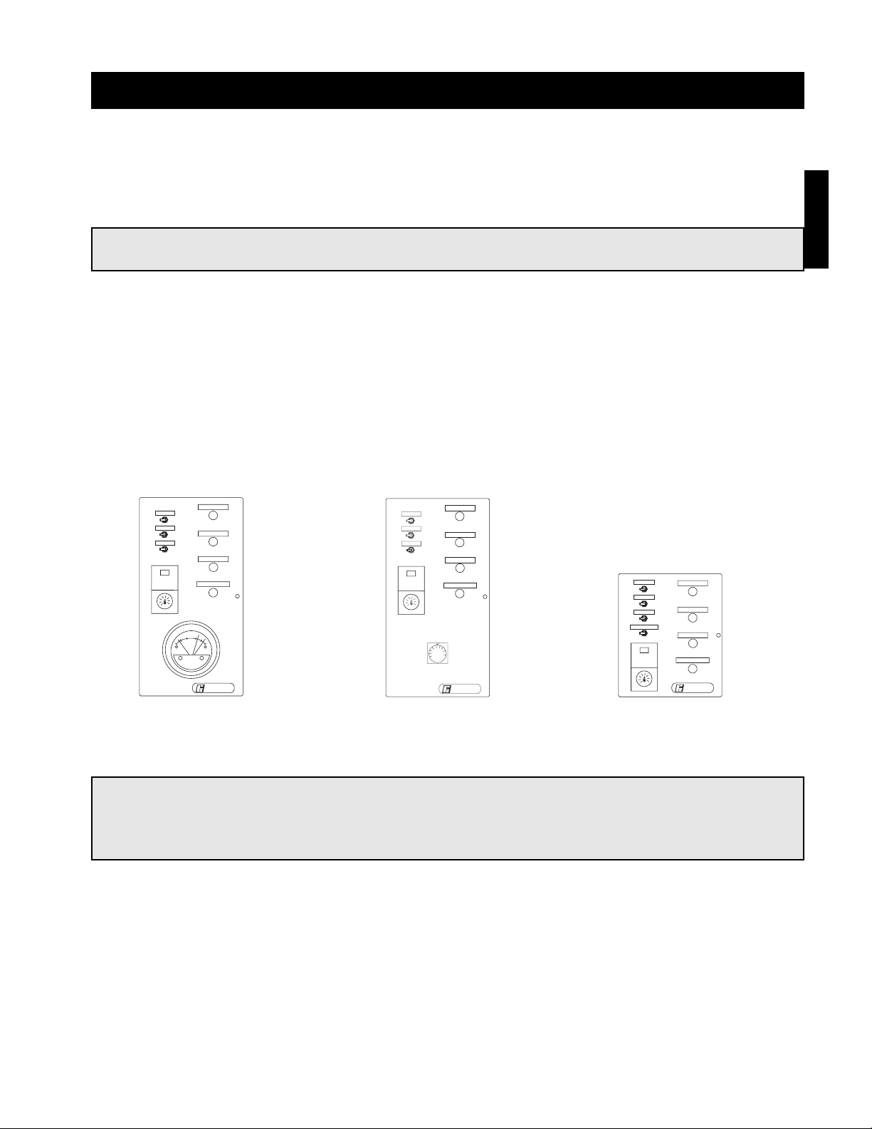
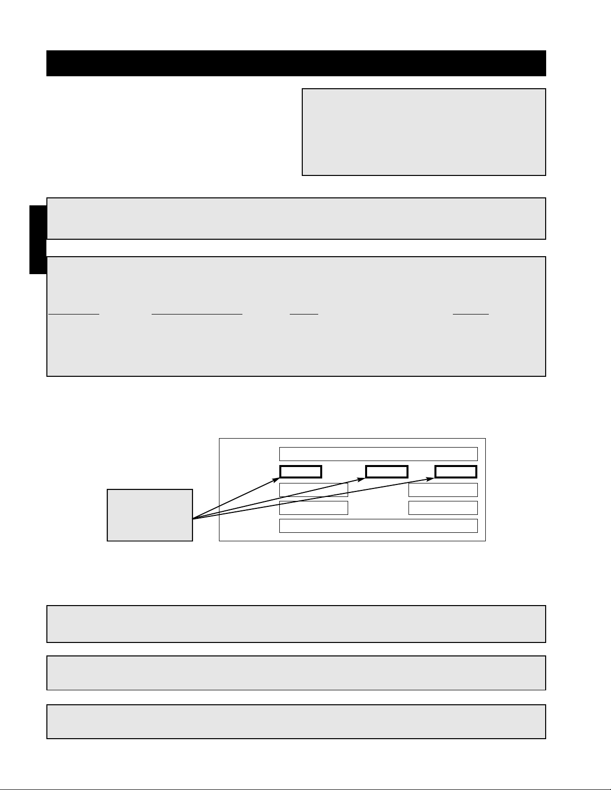
MODEL
VOLTS
SUP HP
MARK
AMPS
HTZ PH
S/N
EXH HP
Voltage, Hertz,
and Phase
Step 1 Check the Voltage
Before starting the unit, compare the supplied voltage, hertz, and phase with the unit and motor’s nameplate
information.
Step 2 Check the Blower Rotation
Open the blower access door and run the blower momentarily to determine the rotation. Arrows are placed on
the blower scroll to indicate the proper direction.
IMPORTANT!
If the blower is rotating in the wrong direction, the unit will move some air, but will not perform as
designed. Be sure to perform a visual inspection to guarantee the correct blower rotation.
SPECIAL EQUIPMENT REQUIRED
Below is a list of special tools that are required. A recommended model is shown, but equivalent
products may be used.
Description
Manufacturer-Model
Phone Website
Voltage Meter Fluke-23 1-800-44-FLUKE www.fluke.com
Amperage Meter Fluke-23 1-800-44-FLUKE www.fluke.com
Thermometer Fluke-50 1-800-44-FLUKE www.fluke.com
U-Tube manometer Dwyer-Slack Tube 1-219-897-8000 www.dwyer-inst.com
Tachometer Monarch-Pocket Tach 100 1-800-999-3390 www.monarchinstruments.com
WARNING!
Disconnect and lock-out all power and gas before
performing any maintenance or service to the
unit. Failure to do so could result in serious injury
or death and damage to equipment.
Pre Start-Up Check
Rotate the fan wheel by hand and make sure no parts
are rubbing. Check the V-belt drive for proper
alignment and tension (a guide for proper belt tension
and alignment is provided in the belt maintenance
section). Check fasteners, set screws and locking
collars on the fan, bearings, drive, motor base and
accessories for tightness. Remove any shipping
fasteners from the blower vibration isolators.
NOTE!
To reverse the rotation on three phase units, disconnect and lock-out the power, then interchange any
two power leads.
NOTE!
To reverse the rotation on single phase units, disconnect and lock-out the power, then rewire the
motor per the manufacturer’s instructions.
Start-Up
WARNING!
Check the housing, blower, weatherhood, filter section and ductwork for foreign objects and debris
before the blower is run.
Page 33
33
Start-Up - Blower
Step 5 Air Volume Measurement and
Check
Measure the unit’s air volume (CFM) and compare it
with its rated air volume. If the air volume is off, adjust
the fan’s RPM’s by changing the drive.
Step 6 Set-up Optional Components
Adjust the settings on the optional components. See the control center layout in the reference section for
location of optional components.
• Heating Inlet Air Sensor (typical setting: 60-70ºF)
• Cooling Inlet Air Sensor (typical setting: 75ºF)
• Building Freeze Protection (typical setting: 5 min at 45ºF)
• Dirty Filter Gauge (typical setting: settings vary greatly for each unit)
• Solid Fuel Time Delay (typical setting varies per application)
NOTE!
The most accurate way to measure the air
volume is by using a pilot traverse method
downstream of the blower. Other methods can
be used but should be proven and accurate.
NOTE!
If your unit is equipped with a 4:1 modulating or 8:1 staged control, the inlet air sensor and building
freeze protection may be included in furnace controller. If this is the case, instructions for setting the
inlet air sensor and building freeze protection are included in the furnace start-up.
IMPORTANT!
Changing the air volume can significantly increase the motor’s amps. If the air volume is changed, the
motor’s amps must be checked to prevent overloading the motor.
Step 3 Check for Vibration
Check for unusual noise, vibration or overheating of the bearings. Reference the troubleshooting section for
corrective actions.
IMPORTANT!
Excessive vibration may be experienced during
the initial start-up. Left unchecked, it can cause
a multitude of problems including structural
and/or component failure.
IMPORTANT!
Generally, fan vibration and noise is transmitted
to other parts of the building by the ductwork.
To minimize this undesirable effect, the use of
heavy canvas duct connectors is recommended.
Step 4 Motor Check
Measure the motor’s voltage, amps and RPM’s and compare to the specifications on the motor’s nameplate.
Check the overload setting and make sure it matches the motor’s amperage rating. If the motor’s actual amps
are greater than the nameplate amps, check and correct the supply voltage or air volume of the blower.
NOTE!
Additional starters and overloads may be provided in the make-up air control center for optional
exhaust blowers. Any additional overloads must be checked for proper voltage, amps and RPM’s.
Start-Up
Page 34

34
Start-up - Furnace (All Units)
NOTE!
There are four furnace control options available. Be sure to refer to the specific instructions for your
control type.
IMPORTANT!
Multi furnace units may use a combination of the available control options. Each furnace must be set-
up per the specific instructions for its control type.
IMPORTANT!
Multi furnace units will use one stage or modulation controller per unit and one or two ignition
controller(s) per furnace. Each furnace will have its own gas valve(s). Each valve must be set for high
and low fire.
IMPORTANT!
For the unit to function properly, all stage or modulating valves must be set for high and low fire.
NOTE!
To force the unit to light for set-up purposes, the heat switch must be closed or jumpered out. See the
ladder diagram on the inside of the control center door for proper terminals to jumper out.
NOTE!
If the unit is equipped with an independent inlet air sensor (not incorporated into the stage or
modulation controller), the unit will not light unless the outside air temperature is less than the inlet
air sensor setting. If the outside air is greater than the inlet air sensor setting, turn the setting to its
maximum position. When set-up is complete, reset the inlet air sensor to the proper temperature. If
the unit is equipped with a stage or modulation controller that includes an inlet air sensor function,
the inlet air sensor will be overridden when the unit is forced to high fire.
Available Control Options
Single Furnace Units
• 1:1 Staged (one 1-stage furnace)
• 2:1 Staged (one 2-stage furnace)
• 8:1 Staged (one 8-stage furnace)
• 2:1 Electronic Modulation (one 2:1 modulating furnace)
• 4:1 Electronic Modulation (one 4:1 modulating furnace)
Two Furnace Units
• 1:1 Staged (two 1-stage furnaces)
• 2:1 Staged (two 1-stage furnaces)
• 4:1 Staged (two 2-stage furnaces)
• 16:1 Staged (one 8-stage and one 1-stage furnace)
• 8:1 Electronic Modulation (one 4:1 modulating and one 2-stage furnace)
Three Furnace Units
• 1:1 Staged (three 1-stage furnaces)
• 3:1 Staged (three 1-stage furnaces)
• 6:1 Staged (three 2-stage furnaces)
• 24:1 Staged (one 8-stage and two 1-stage furnaces)
• 12:1 Electronic Modulation (one 4:1 modulating, one 2-stage and one 1-stage furnace)
Start-up
Page 35
35
Start-Up - Single Stage Control
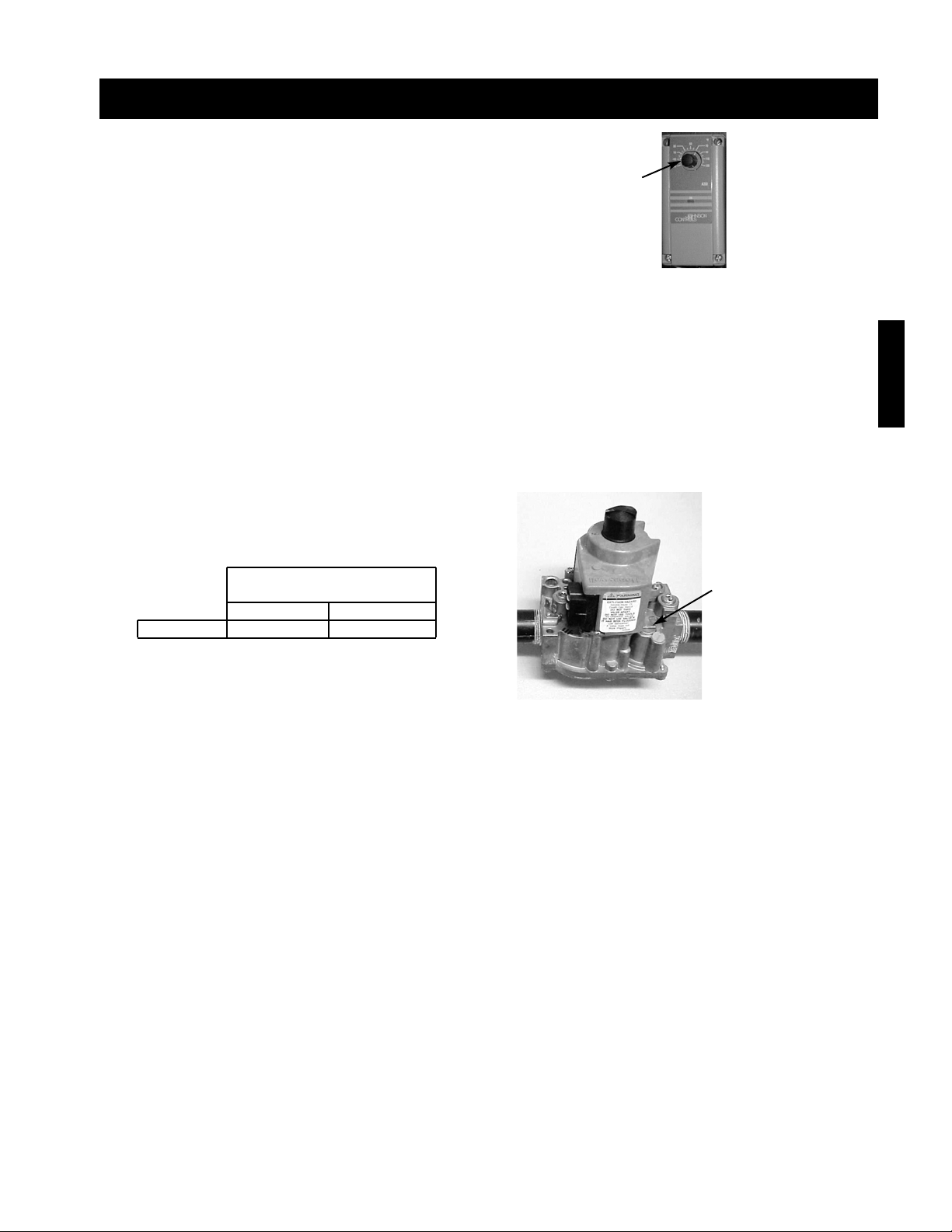
Step 1 Send Unit to High Fire
Send the unit to high fire by setting the temperature
selector to its maximum setting.
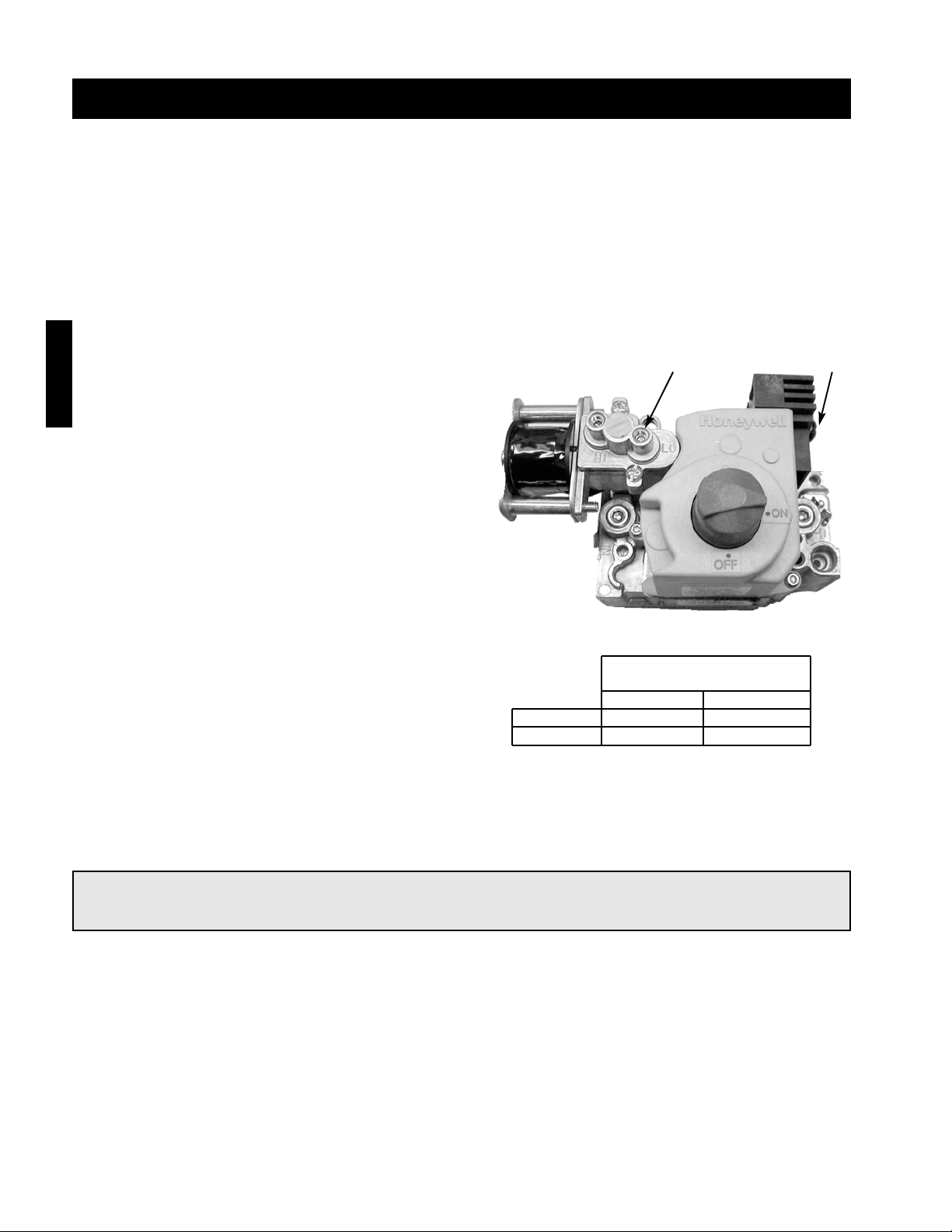
Step 2 Check the High Fire Manifold Pressure
Using a manometer, measure the burner manifold pressure at the manifold pressure test port. Refer to the gas
train layout in the reference section for the test port location.
The pressure on high fire should be 3
1
⁄2 inches wc for natural gas and 10 inches wc for LP gas.
If needed, use the high fire adjustment screw on the staged gas valve to adjust the high fire manifold pressure.
Counterclockwise rotation will decrease the gas pressure and clockwise rotation will increase the gas pressure.
Step 3 Reset the Temperature Setting
Reset the temperature setting on the temperature selector to the desired setting.
Single Stage Manifold
Pressure (inches wc)
Natural Gas LP
High Fire 3
1
⁄2 10
Start-Up
Temperature
Selector
High Fire
Adjustment
Page 36
36
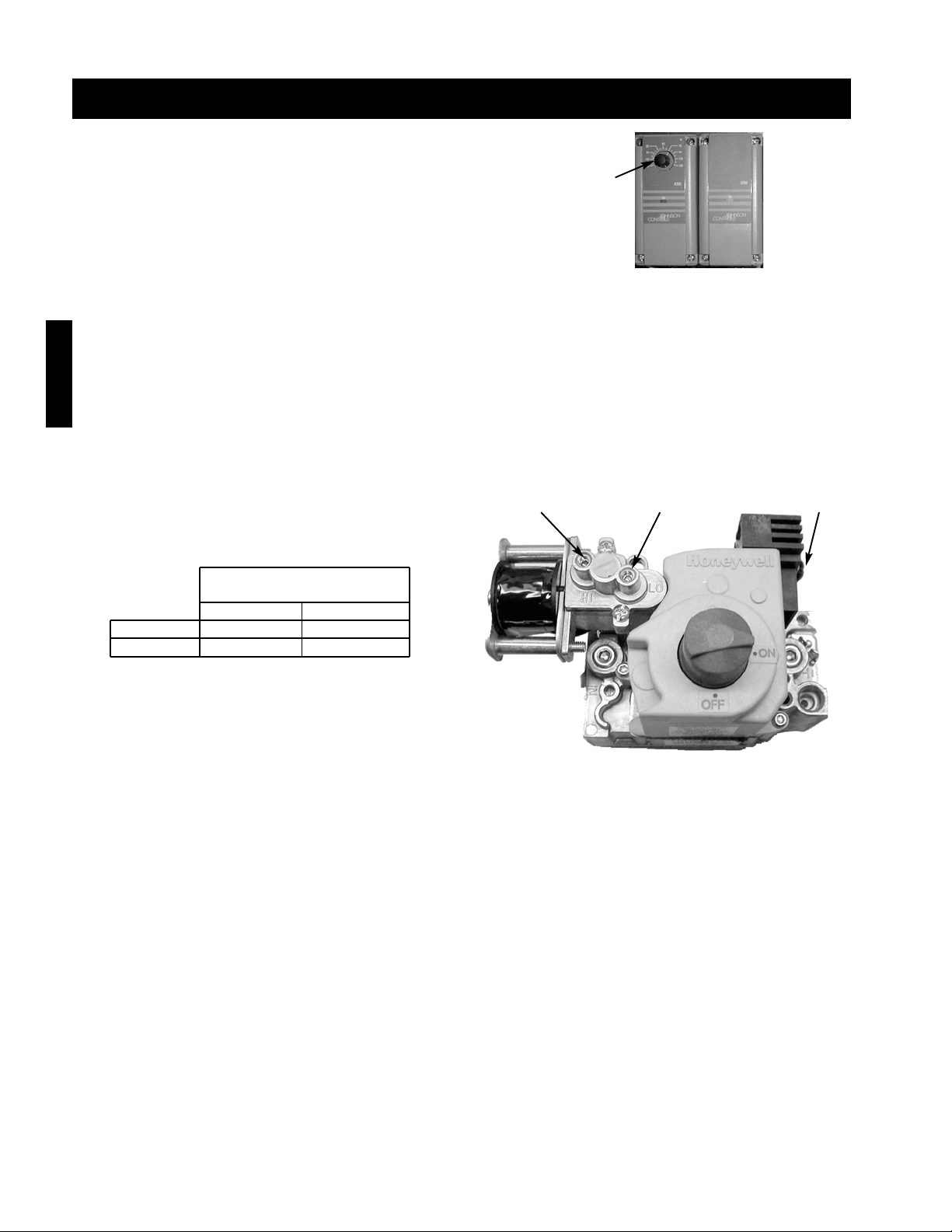
High Fire
Adjustment
Low Fire
Adjustment
High Fire
Terminal
Start-Up - 2:1 Staged Control
Step 1 Send Unit to High Fire
Send the unit to high fire by setting the temperature
selector to its maximum setting.
Step 3 Send Unit to Low Fire
Remove and isolate the wire from the high fire terminal on the combination gas valve to send the unit to low fire.
Step 2 Check the High Fire Manifold Pressure
Using a manometer, measure the burner manifold pressure at the manifold pressure test port. Refer to the gas
train layout in the reference section for the test port location.
The pressure on high fire should be 3
1
⁄2 inches wc for natural gas and 10 inches wc for LP gas.
If needed, use the high fire adjustment screw on the combination gas valve to adjust the high fire manifold
pressure. Counterclockwise rotation will decrease the gas pressure and clockwise rotation will increase the gas
pressure.
Step 4 Check the Low Fire Manifold Pressure
Using a manometer, measure the burner manifold pressure at the manifold pressure test port. Refer to the gas
train layout in the reference section for the test port location.
The pressure on low fire should be
7
⁄8 inches wc for natural gas and 21⁄2 inches wc for LP gas.
If needed use the low fire adjustment screw on the combination gas valve to adjust the low fire manifold
pressure. Counterclockwise rotation will decrease the gas pressure and clockwise rotation will increase the gas
pressure. Once the low fire manifold pressure is set, reattach the high fire wire to the high fire terminal.
Step 5 Reset the Temperature Setting
Reset the temperature setting on the temperature selector to the desired setting.
Two Stage Manifold
Pressure (inches wc)
Natural Gas LP
Low Fire
7
⁄8 21⁄2
High Fire 31⁄2 10
Temperature
Selector
Start-Up
Page 37
37
Start-Up - 8:1 Staged Control
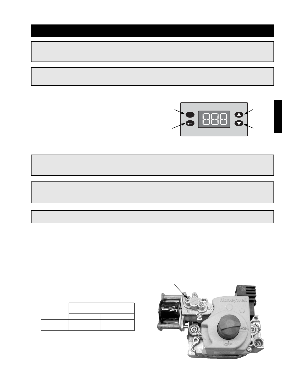
Step 1 Send the Unit to High Fire
For the furnace to light, the heat switch must be
closed or jumpered out. Reference the unit ladder
diagram for proper terminals to jumper.
To send the unit to high fire, press and hold the up,
down and enter keys. “HIF” will flash on the screen
when the unit is forced to high fire.
The unit will remain at high fire until the escape key is
pressed (“HIF” will stop flashing).
WARNING!
Once the unit is forced to high fire, it will remain at high fire until the escape key is pressed.
NOTE!
A second high limit with manual reset is located in the control center of the unit.
NOTE!
Forcing the unit to high fire during warm or hot weather conditions may cause the high limit switch to
trip. If the switch trips, it will reset once the discharge air temperature has reached a safe level.
Start-Up
IMPORTANT!
8:1 staged furnaces use two manifolds and two staged gas valves per furnace. The high and low fire
manifold pressure must be checked and properly set on each manifold.
IMPORTANT!
Confirm that the discharge air sensor is installed in the duct, at least three duct diameters
downstream of the furnace
Step 2 Check the High Fire Manifold Pressure
Using a manometer, measure the high fire burner manifold pressure for each furnace at the pressure test port.
Refer to the gas train layout in the reference section for the test port location.
The recommended high fire manifold pressure is 3
1
⁄2 inch wc for natural gas and 10 inch wc for LP Gas.
If needed, adjust the high fire screws on each staged gas valve to set both high fire manifold pressures.
Counterclockwise rotation will decrease the gas pressure and clockwise rotation will increase the gas pressure.
Eight Stage Manifold
Pressure (inches wc)
Natural Gas LP
Low Fire
7
⁄8 21⁄2
High Fire 31⁄2 10
High Fire
Adjustment
Escape
DownEnter
Up
Page 38
38
Step 3 Send the Unit to Low Fire
Disconnect and isolate the wire from the high fire terminal to send the unit to low fire.
WARNING!
Once the high and low fire have been set, be sure the press the escape key to end high fire mode. The
display will stop flashing “HIF” when high fire mode is off.
Step 4 Check the Low Fire Manifold
Pressure
Measure each valve’s low fire manifold pressure.
The recommended low fire manifold pressure is
7
⁄8 inch
wc for natural gas and 21⁄2 inches wc for LP.
If needed, use the low fire adjustment screw on each
staged gas valve to properly set both low manifold
settings. Counterclockwise rotation will decrease the
gas pressure and clockwise rotation will increase the
gas pressure.
When the low fire manifold pressure is properly set,
reattach the disconnected wire to the high fire
terminal, allow the heat switch to close or remove the
jumper (see step #1).
Start-Up - 8:1 Staged Control
Eight Stage Manifold
Pressure (inches wc)
Natural Gas LP
Low Fire
7
⁄8 21⁄2
High Fire 31⁄2 10
Low Fire
Adjustment
High Fire
Terminal
Start-Up
Page 39
39
NOTE!
Step 5-7 are for adjusting the discharge air setting. The discharge air temperature setting is factory
set to the recommended 70ºF. Only adjust the setting if needed.
NOTE!
After modifying a setting, the enter key must be pressed to save the change. If the enter key is not
pressed the display will return to the program menu without saving the change.
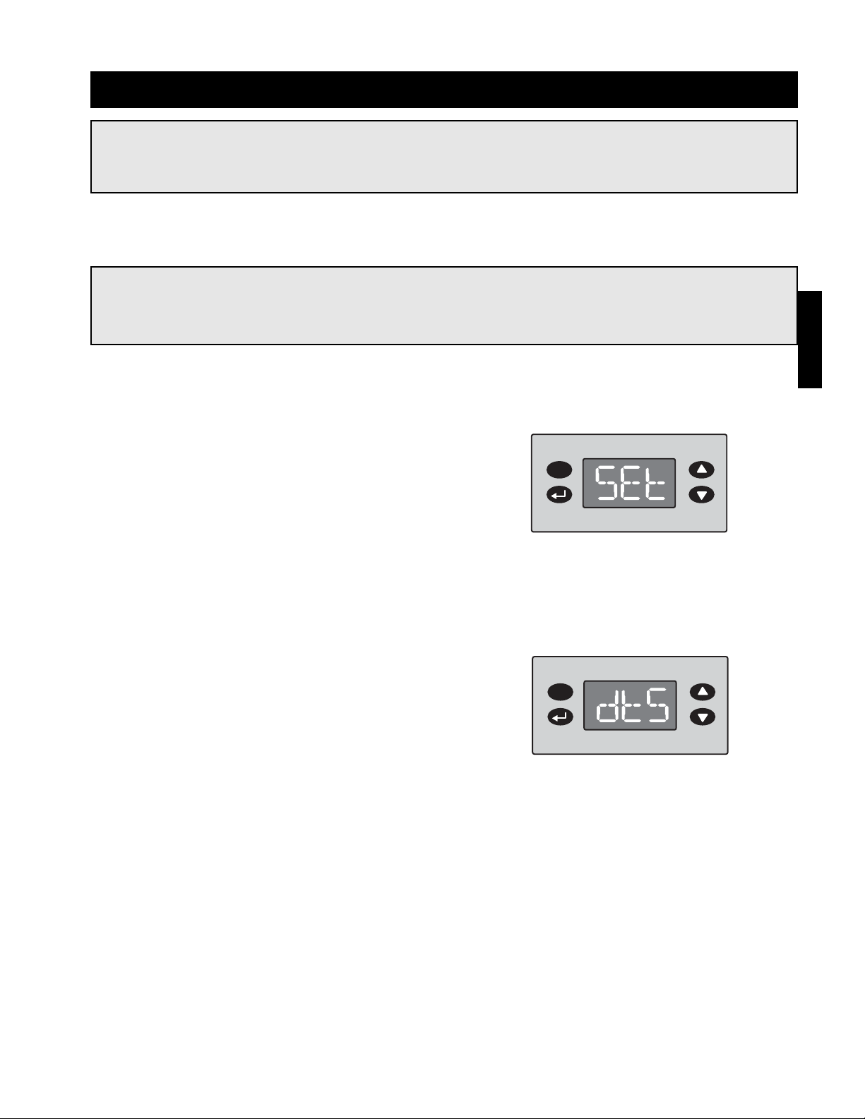
Step 6 Access the Discharge Air
Temperature Setting
Using the up or down key, scroll through the program
menu until the display reads “dtS,” then press the
enter key. The display will change to the discharge air
temperature setting.
Step 5 Access the Program Menu
Press and hold the escape key for three seconds to
access the program menu. The display will read
“SEt.”
Step 7 Edit the Setting
Use the up or down keys to change the discharge air temperature setting. When the correct setting is displayed,
press the enter key to save the setting and return to the program menu.
Start-Up - 8:1 Staged Control
Start-Up
Page 40
40
Start-Up - 8:1 Staged Control
Start-Up
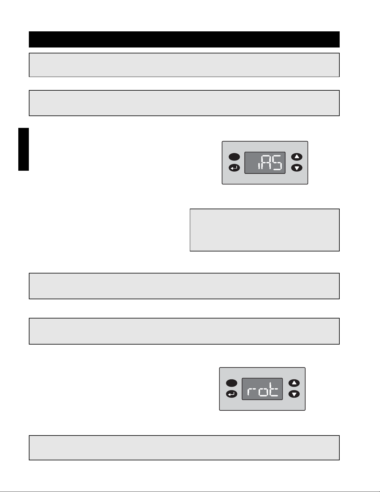
Step 8 Access the Inlet Air Sensor
Setting
From the program menu, use the up or down key to
navigate through the menu options until the display
reads “iAS.” Once the display reads “iAS,” press the
enter key. The display will change to the inlet air
sensor setting.
NOTE!
Steps 8 - 9 are provided for adjusting the inlet air set point. The inlet air sensor is preset to the
factory recommended 65ºF, only adjust if needed.
NOTE!
The inlet air sensor monitors the temperature of the inlet air. If the inlet air is above the sensor’s set
point, the inlet air sensor shuts off the furnace and continues to supply the warm outside air.
NOTE!
After modifying a setting, the enter key must be
pressed to save the change. If the enter key is
not pressed the display will return to the
program menu without saving the change.
NOTE!
The room override function requires a field supplied thermostat to be installed in the space and to be
wired between terminal 31 and 32 in the unit’s control center. Reference the unit ladder diagram.
Step 9 Edit the Setting
Use the up or down keys to change the inlet air
setting. When the correct setting is displayed, press
the enter key to save the setting and return to the
program menu.
NOTE!
Steps 10 - 11 are provided for adjusting the room override setting. Only adjust the setting if the room
override function is desired.
NOTE!
The room override function temporarily changes the discharge air temperature to the room override
setting if the room thermostat is not satisfied.
Step 10 Access the Room Override
Setting
From the program menu, use the up or down key to
navigate through the menu options until the display
reads “rot.” Once the display reads “rot,” press the
enter key. The display will change to the room
override setting.
Page 41
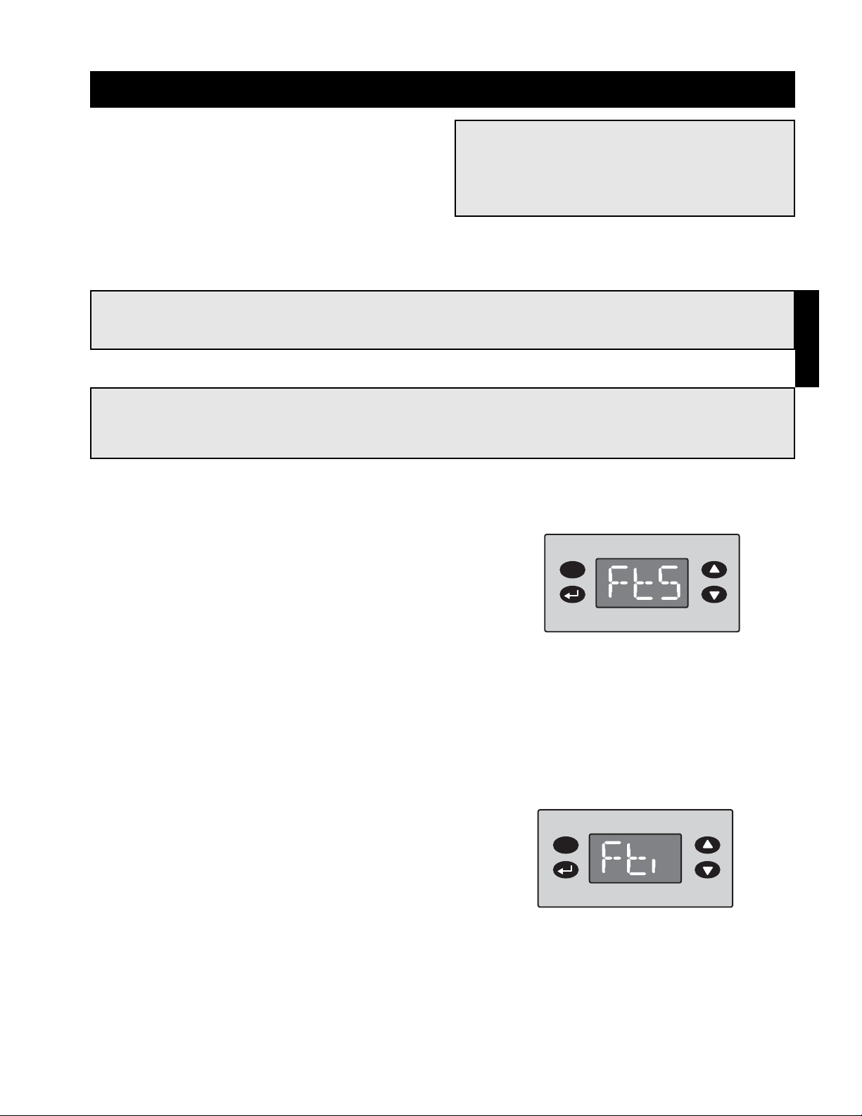
41
Start-Up - 8:1 Staged Control
NOTE!
If the discharge temperature drops below the freeze temperature setting and remains below the
setting for longer than the time delay setting, the blower and burner will shut down to prevent the
discharge of cold air into the building.
NOTE!
The freeze temperature and time delay setting are set to the factory recommended 45ºF and
300 seconds respectfully. Only follow steps 12 - 13 if you wish to change the recommended settings.
Step 12 Access the Freeze Temperature
Setting
From the program menu, use the up or down key to
navigate through the menu options until the display
reads “FtS”. Once the display reads “FtS,” press the
enter key. The display will change to the freeze
temperature setting.
Step 13 Edit the Setting
Use the up or down keys to change the freeze temperature setting. When the correct setting is displayed, press
the enter key to save the setting and return to the program menu.
Step 14 Access Time Delay Setting
From the program menu, use the up or down key to
navigate through the menu options until the display
reads “Fti.” Once the display reads “Fti,” press the
enter key. The display will change to the time delay
setting. The time is displayed in ten second
increments (1 = 10 sec).
Step 15 Edit the Setting
Use the up or down keys to change the time delay setting. When the correct setting is displayed, press the enter
key to save the setting and return to the program menu.
Start-Up
Step 11 Edit the Setting
Use the up or down keys to change the room override
setting. When the correct setting is displayed, press
the enter key to save the setting and return to the
program menu.
NOTE!
After modifying a setting, the enter key must be
pressed to save the change. If the enter key is
not pressed the display will return to the
program menu without saving the change.
Page 42

42
Start-Up
Start-Up - 2:1 Electronic Modulation
NOTE!
The low fire manifold pressure should always be
rechecked after adjusting the high fire.
Step 1 Send Unit to High Fire
Turn the temperature selector to its maximum setting to send the unit to high fire.
Step 3 Send Unit to Low Fire
Remove and isolate one wire from the modulating gas valve terminal to send the unit to low fire.
Step 2 Check the High Fire Manifold Pressure
With the unit at high fire, use a manometer to measure the burner manifold pressure at the manifold pressure
test port. See the gas train layout in the reference section for the manifold pressure test port location.
The recommended high fire manifold pressure is 31⁄2 inches wc for natural gas and 10 inches wc for LP Gas.
If needed, use the high fire adjustment screw on the shut-off gas valve to adjust the high fire manifold pressure.
Counterclockwise rotation will decrease the gas pressure and clockwise rotation will increase the gas pressure.
Step 4 Check the Low Fire Manifold Pressures
With the unit at low fire, use a manometer to measure the burner manifold pressure at the manifold pressure test
port. See the gas train layout in the reference section for the manifold pressure test port location.
The recommended low fire manifold pressure is
7
⁄8 inch wc for natural gas and 21⁄2 inches wc for LP Gas.
If needed use the low fire adjustment screw on the modulating gas valve to adjust the low fire manifold pressure.
Counterclockwise rotation will decrease the gas pressure and clockwise rotation will increase the gas pressure.
Once the low fire is set, reattach the disconnected wire to the modulating valve and reset the temperature
selector.
2:1 Manifold
Pressure (inches wc)
Natural Gas LP
Low Fire
7
⁄8 21⁄2
High Fire 31⁄2 10
Low Fire
Adjustment
Terminal
High Fire
Adjustment
IMPORTANT!
Once the high and low fire manifold pressures
are properly set, reset the discharge air
temperature to the desired setting.
Page 43

43
Start-Up - 4:1 Electronic Modulation
High Fire
Adjustment
Step 2 Check the High Fire Manifold
Pressure
Using a manometer, measure the high fire manifold
pressure at the pressure test port. Refer to the gas
train layout in the reference section for the test port
location.
The recommended high fire manifold pressure is 3
1
⁄2
inches wc for natural gas and 10 inches wc for LP
Gas.
If needed, adjust the high fire screw on the shut-off
valve to set the high fire manifold pressure.
Counterclockwise rotation will decrease the gas
pressure and clockwise rotation will increase the gas
pressure.
Step 1 Send the Unit to High Fire
To send the unit to high fire, press and hold the up,
down and enter keys. The unit will remain at high fire
until the escape key is pressed.
WARNING!
If the unit is forced to high fire, it will remain at high fire until the escape key is pressed.
NOTE!
Forcing the unit to high fire in mild weather conditions may cause the high limit switch to trip. If the
switch trips, it will reset once the discharge air temperature is at a safe level.
NOTE!
A second high limit with a manual reset is located in the control center.
NOTE!
After modifying a setting, the enter key must be pressed to save the change. If the enter key is not
pressed the display will return to the program menu without saving the change.
Step 3 Send Unit to Low Fire
Remove and isolate one wire from the modulating gas valve terminal to send the unit to low fire.
Start-Up
Escape
DownEnter
Up
4:1 Modulation Manifold
Pressure (in. wc)
Natural Gas LP
Low Fire
1
⁄3 1
High Fire 31⁄2 10
Page 44

44
Start-Up - 4:1 Electronic Modulation
4:1 Modulation Manifold
Pressure (in. wc)
Natural Gas LP
Low Fire
1
⁄3 1
High Fire 31⁄2 10
NOTE!
The low fire manifold pressure must be
rechecked after adjusting the high fire.
Step 5 Exit High Fire Mode
Press the escape key to exit high fire mode
Step 4 Check the Low Fire Manifold Pressures
With the unit at low fire use a manometer to check the manifold pressure. Refer to the gas train layout in the
reference section for the test port location.
The recommended low fire manifold pressure is 1⁄3 inches wc for natural gas and 1.0 inches wc for LP Gas.
If needed, use the low fire adjustment screws on the modulating valve to adjust the low fire manifold pressure.
Counterclockwise rotation will decrease the gas pressure and clockwise rotation will increase the gas pressure.
Once the low fire manifold pressure is set, reattach the wire to the modulating gas valve terminal.
Low Fire
Adjustment
Terminal
Step 7 Access the Discharge Air
Temperature Setting
Use the up and down key to scroll through the
program menu options until the display reads “dtS,”
then press the enter key. The display will change to
the discharge air temperature setting.
Step 6 Access the Program Menu
Press and hold the escape key for three seconds to
access the program menu. The display will read “SEt”
when program mode is active.
NOTE!
The following steps are for adjusting the discharge air setting. The discharge air temperature setting
is factory set to the recommended 70º F. Only adjust the setting if needed.
NOTE!
After modifying a setting, the enter key must be pressed to save the change. If the enter key is not
pressed the display will return to the program menu without saving the change.
Step 8 Edit the Setting
Use the up or down keys to change the discharge air temperature setting. When the correct setting is displayed,
press the enter key to save the setting and return to the program menu.
Start-Up
Page 45

45
Start-Up - 4:1 Electronic Modulation
Step 9 Access the Inlet Air Sensor
Setting
From the program menu, use the up or down key to
navigate through the menu options until the display
reads “iAS.” Once the display reads “iAS,” press the
enter key. The display will change to the inlet air
sensor setting.
NOTE!
Steps 8 - 10 are provided for adjusting the inlet air set point. The inlet air sensor is preset to the
factory recommended 60ºF, only adjust if needed.
NOTE!
The inlet air sensor monitors the temperature of the inlet air. If the inlet air is above the sensor’s set
point, the inlet air sensor shuts off the furnace and continues to supply the warm outside air.
NOTE!
After modifying a setting, the enter key must be
pressed to save the change. If the enter key is
not pressed the display will return to the
program menu without saving the change.
NOTE!
The room override function requires a field supplied thermostat to be installed in the space and to be
wired between terminal 31 and 32 in the unit’s control center.
Step 10 Edit the Setting
Use the up or down keys to edit the inlet air setting.
When the correct setting is displayed, press the enter
key to save the setting and return to the program
menu.
NOTE!
Steps 11 - 12 are provided for adjusting the room override setting. Only adjust the setting if the room
override function is desired.
NOTE!
The room override function temporarily changes the discharge air temperature to the room override
setting if a room thermostat is not satisfied.
Step 11 Access the Room Override
Setting
From the program menu, use the up or down key to
navigate through the menu options until the display
reads “rot.” Once the display reads “rot,” press the
enter key. The display will change to the room
override setting.
Start-Up
Page 46

46
NOTE!
If the discharge temperature drops below the freeze temperature setting and remains below the
setting for longer than the time delay setting, the blower and burner will shut down to prevent the
discharge of damagingly cold air into the building.
NOTE!
The freeze temperature and time delay setting are set to the factory recommended 45ºF and 300
seconds respectfully. Only follow steps 13-16 if you wish to change the factory settings.
Step 13 Access the Freeze Temperature
Setting
From the program menu, use the up or down key to
navigate through the menu options until the display
reads “FtS”. Once the display reads “FtS,” press the
enter key. The display will change to the freeze
temperature setting.
Step 14 Edit the Setting
Use the up or down keys to change the freeze temperature setting. When the correct setting is displayed, press
the enter key to save the setting and return to the program menu.
Step 15 Access Time Delay Setting
From the program menu, use the up or down key to
navigate through the menu options until the display
reads “Fti.” Once the display reads “Fti,” press the
enter key. The display will change to the time delay
setting. The time is displayed in ten second
increments (1 = 10 sec).
Step 16 Edit the Setting
Use the up or down keys to change the time delay setting. When the correct setting is displayed, press the enter
key to save the setting and return to the program menu.
Step 12 Edit the Setting
Use the up or down keys to change the room override
setting. When the correct setting is displayed, press
the enter key to save the setting and return to the
program menu.
NOTE!
After modifying a setting, the enter key must be
pressed to save the change. If the enter key is
not pressed the display will return to the
program menu without saving the change.
Start-Up - 4:1 Electronic Modulation
Start-Up
Page 47

47
Start-Up
Start-Up - Mixing Box (Optional)
Step 2 Set Minimum Outside Air
Set the minimum outside air position. HV-1 is designed for 0-30% outside air and HV-2 is designed for 31-75%
outside air.
All economizer options (EC-1, EC-2, EC-3 and EC-4) and mixing box option MB-1 use a potentiometer to set the
minimum outside air damper position. The potentiometer is located on the economizer for options EC-1, EC-2,
EC-3 and EC-4. The potentiometer may be factory mounted in the unit control center or field mounted in the
space for option MB-1.
MB-2 and MB-3 use an external signal from a building management system to position the dampers
MB-4 uses a manual quadrant located on the inlet damper to position the dampers.
Step 1 Verify Sensor Installation
All economizer options (EC) require an outdoor air temperature or enthalpy sensor to be field installed inside of
the weatherhood and field wired to terminals SO+ and SO- on the economizer.
Economizer options EC-3 and EC-4 require an outdoor air temperature or enthalpy sensor to be field installed in
the return air duct and field wired to terminals SR+ and SR- on the economizer.
Verify that all economizer sensors needed for your application are properly installed and wired.
NOTE!
Units with a mixing box are designed for either 0-30% outside air (HV-1), 31-75% outside air (HV-2) or
100% return air (HV-3). Refer to the CAPS submittal for the unit’s ventilation type.
NOTE!
HV-1 and HV-2 use economizer controls (EC) or mixing box controls (MB).
NOTE!
Economizer control may use outside air temperature reference (EC-1), outside enthalpy reference (EC-
2), differential temperature reference (EC-3) or differential temperature reference (EC-4).
IMPORTANT!
The outside air volume must be measured and compared to the total air volume when setting the
minimum outside air. The minimum outside air should never be set based on the inlet damper or
potentiometer position.
NOTE!
Mixing box control may use a potentiometer (MB-1), 2-10VDC signal (MB-2), 4-20mA signal (MB-3) or a
manual quadrant (MB-4).
NOTE!
To prevent premature heat exchanger failure, do not locate units where chlorinated, halogenated, or
acid vapors are present.
Page 48
48
Start-Up - Mixing Box (Optional)
Step 3 Set the Enthalpy Changeover Set Point (Optional)
If using an economizer, the enthalpy changeover setting must be set. If differential temperature or differential
enthalpy control is used, set the enthalpy changeover set point to D. If outside air temperature or enthalpy
reference is used, set the enthalpy changeover set point to the desired setting from the following table.
Step 4 Program Optional Room Stat
Program the optional room stat. Separate detailed instructions for programming the room stat ship with the
optional room stat.
NOTE!
For options EC-3 and EC-4 the enthalpy changeover set point is the temperature at which the
economizer will send the dampers to the minimum outside air position.
Enthalpy Changeover Setting
Setting
Changeover
Temperature* (ºF)
A73
B70
C67
D63
* Temperature at 50% relative humidity, see the Honeywell W7212
Economizer instructions for set points at other humidities.
Start-Up
Page 49
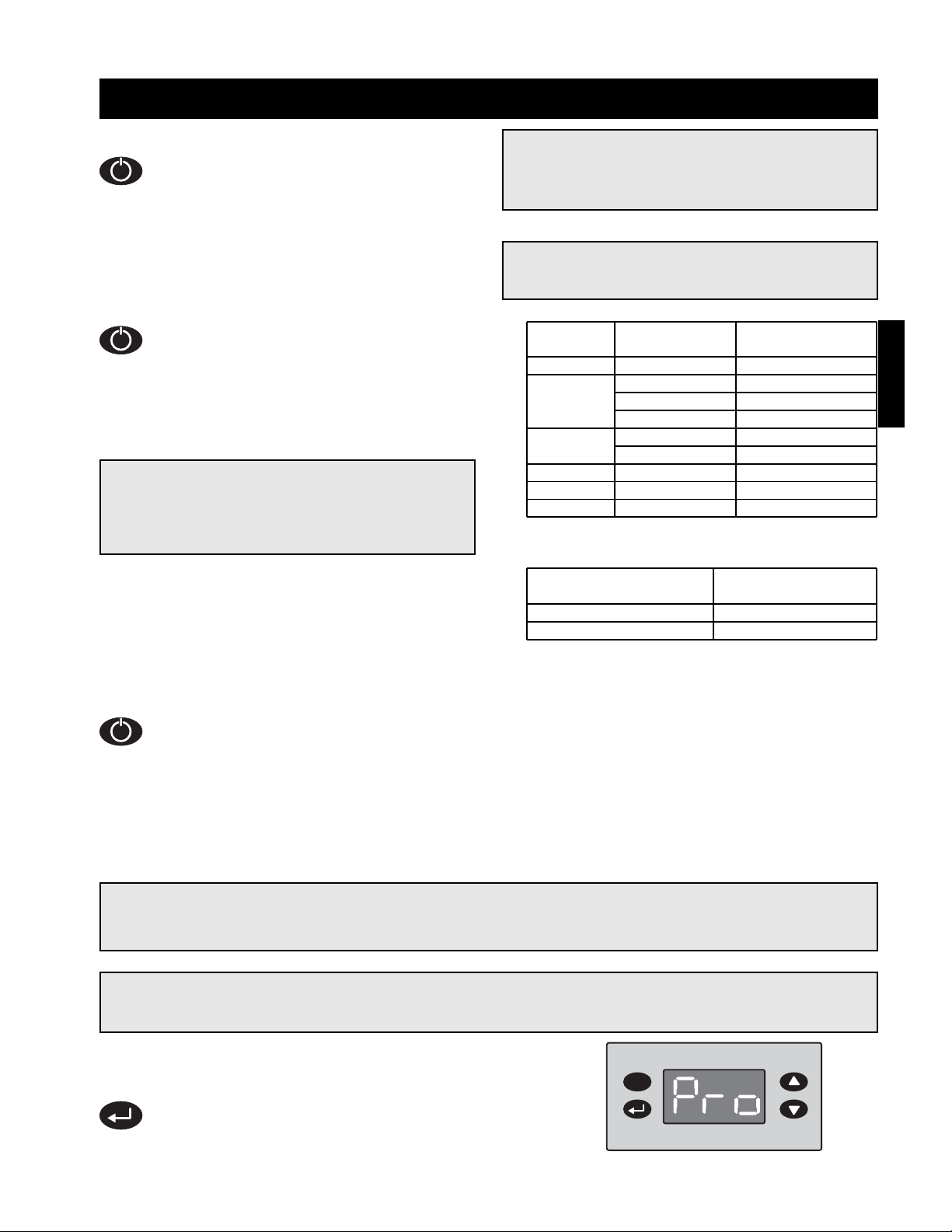
49
NOTE!
Steps 6-8 are provided to adjust the minimum cooling temperature. The minimum cooling temperature
is preset to the factory recommended 75ºF. Only adjust if needed.
NOTE!
The inlet air sensor function overrides and shuts down the evaporative cooler if the outside
temperature falls below the minimum cooling temperature.
Step 6 Enter Program Mode
Press and hold the enter key for three seconds.
The display will read “Pro” when program mode is
active.
Start-Up - Water Wizard (Optional)
NOTE!
The manual supply valve ships closed and must
be adjusted for proper performance.
NOTE!
The recommended water pressure for the model
IGX is set based on media width, model IG is set
based on air volume. A table is provided for
each. Be sure to refer to the correct table.
WARNING!
Opening the manual supply valve will allow water
to pass to the media. Be sure the sump is safely
draining before opening the manual supply valve.
Step 2 Set the Water Pressure
With the solenoid open, set the supply
water pressure to the correct setting from
the following tables. Use the manual supply
valve to adjust the supply pressure. A
pressure gauge is provided between the
manual supply valve and the media.
Step 3 Break-in Media
Leave the supply solenoid open to saturate
and break-in the media for 20 minutes with
the blower off.
Step 4 Close Solenoid
With the pressure set, press the function key for one second to deactivate flow test mode and allow
the supply solenoid to close.
Step 5 Check Media
Start the cooling cycle and check the media after one hour of operation. If the media is continuously
dry or if too much water is draining from the sump tank, refer to Water Wizard troubleshooting.
*Multiple media sections. Values represents total media width.
Step 1 Open the Solenoid
Confirm that the manual water supply valve
is closed. Press and hold the function
button for one second. L3 (refer to Water
Wizard operation in the reference section)
will begin blinking (short on, long off),
indicating that flow test mode is active and
the supply solenoid is open.
Start-Up
Model IG Water Pressure
CFM Range (in w.c.)
800 - 3500 50
3501 - 7000 74
IGX
Media Width Water Pressure
Housing
(inches) (in. w.c)
12 30 20
43
3
⁄4 36
22 48 42
60 61
32
66 72
96* 42
35 120* 61
38 180* 37
42 216* 51
Page 50
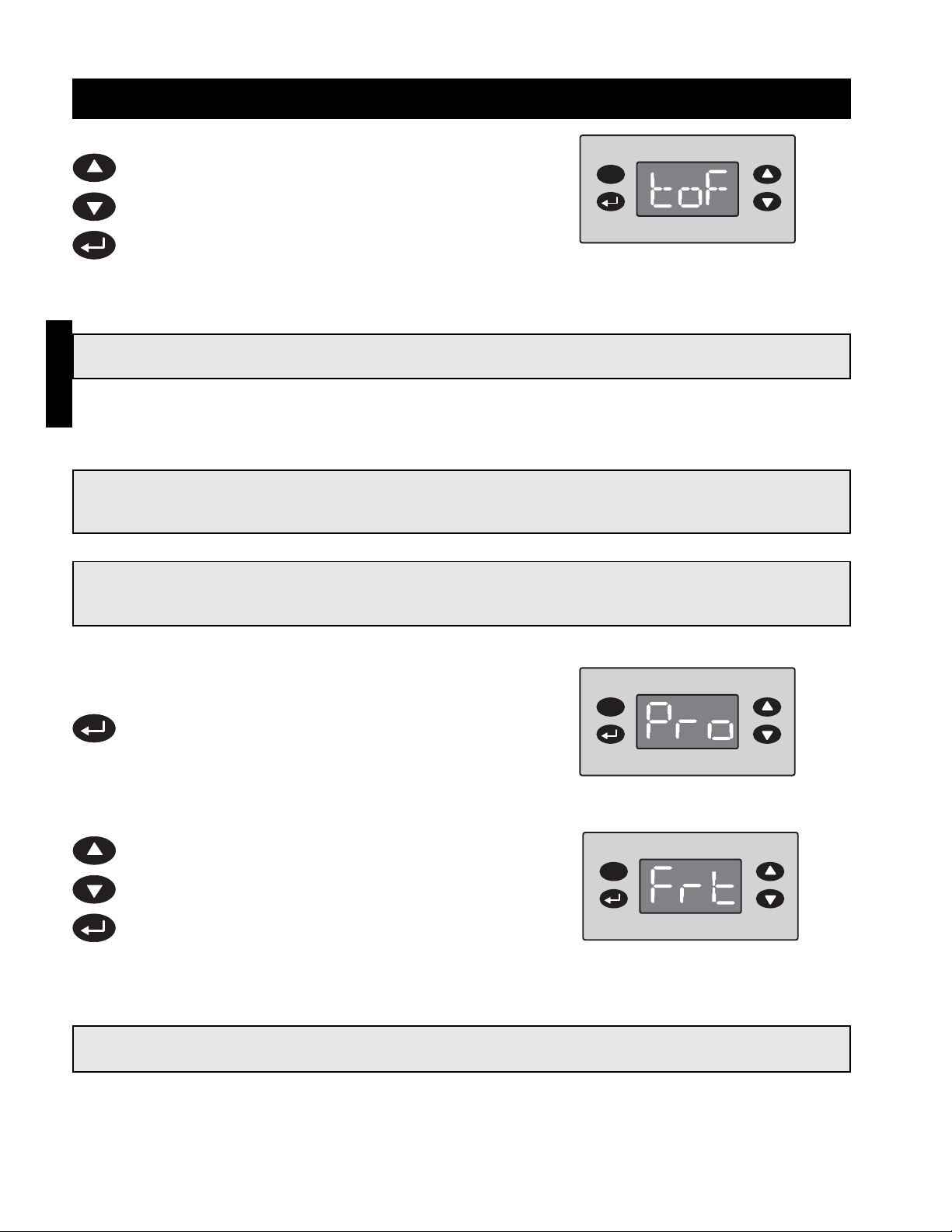
50
Step 9 Enter Program Mode
Press and hold the enter key for three seconds.
The display will read “Pro” when program mode is
active.
Step 10 Adjust the Freeze Temperature
While in program mode, use the up and down keys
to navigate through the menu options until “Frt” is
displayed. Press the enter key to access the
selected menu option setting. Use the up and
down keys to adjust the freeze temperature setting
as needed. Press the enter key to set the freeze
temperature and return to the program menu.
Step 11 Exit Program Mode
After ten seconds of idle time the controller will exit program mode.
Step 8 Exit Program Mode
After ten seconds of idle time the controller will exit program mode.
NOTE!
The freeze temperature is the temperature at which the supply solenoid closes and the drain solenoid
opens to drain the supply line, preventing possible freeze damage.
NOTE!
Steps 9-11 are provided to adjust the freeze temperature setting. The freeze temperature is preset to
the factory recommended 45ºF. Only adjust if needed.
Step 7 Adjust the Minimum Cooling
Temperature
While in the program menu, use the up and down
keys to navigate the menu options until “toF” is
displayed. Press the enter key to access the
selected menu option setting. Use the up and
down keys to adjust the minimum cooling
temperature as needed. Press the enter key to
save the new minimum cooling temperature setting
and return to the program menu.
IMPORTANT!
The enter key must be pressed to save the new freeze temperature.
IMPORTANT!
The enter key must be pressed to save the new minimum cooling temperature.
Start-Up - Water Wizard (Optional)
Start-Up
Page 51
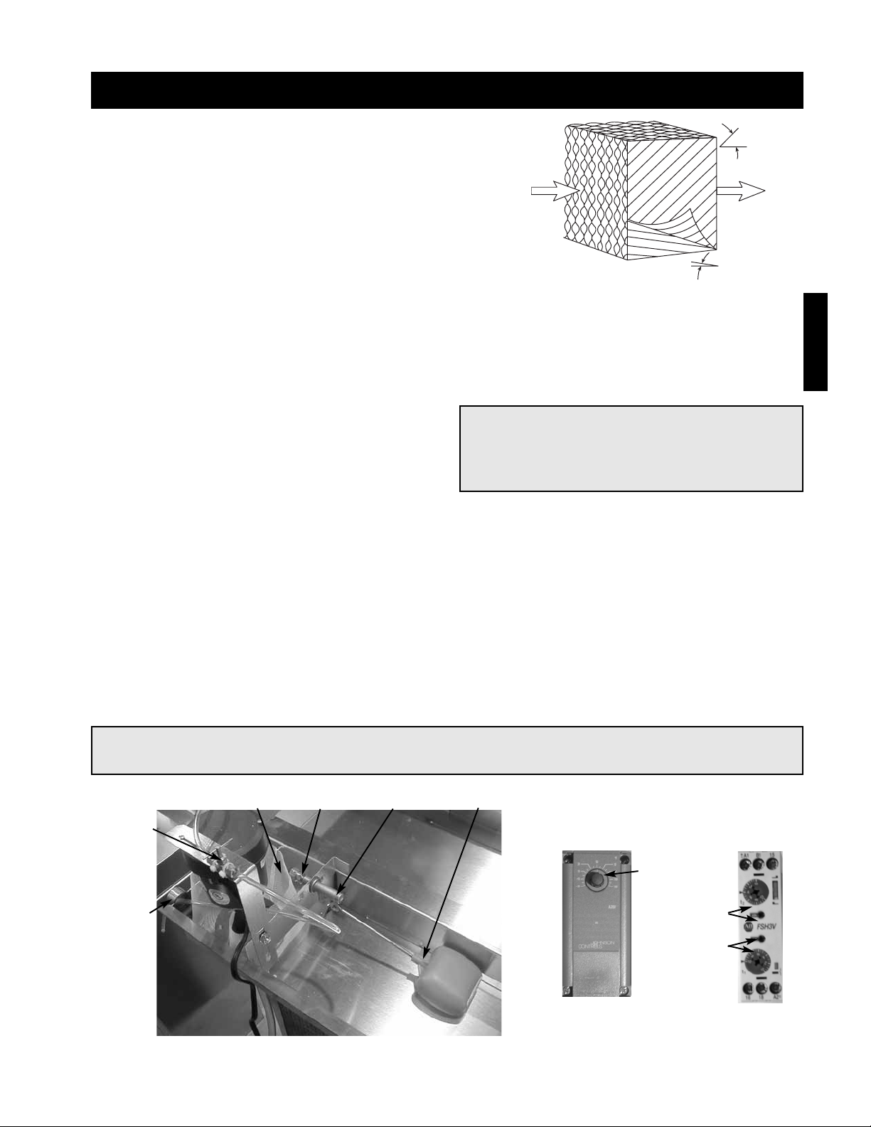
51
Step 6 Adjust the Water Bleed-Off Rate
The water bleed-off rate is dependent on the water’s mineral content. The bleed-off should be adjusted based
on the media’s mineral deposits after two weeks of service.
Step 8 Put the Unit into Service
Remove the jumper, and energize the blower(s). Verify proper operation.
Start-Up - Evaporative Cooling (Optional)
Step 1 Check the Installation
The media may have been removed during installation, so its
orientation should be double checked. The media should be
installed with the steeper flute angle sloping down towards the
entering air side.
Verify that the stainless steel caps and distribution headers
are in place. The headers should be located over the media
towards the entering air side. The caps should be placed over
the headers.
Leaving Air
Entering Air
45°
15°
Step 2 Check the Pump Filter
Check that the pump filter is around the pump inlet.
Step 3 Fill the Sump and Adjust the Float
Turn on the water supply and allow the sump tank to fill. Adjust the float valve to shut-off the water supply when
the sump is filled to within 1 in. of the bottom of the overflow.
Step 5 Check the Flow Rate
The pumps should provide enough water to saturate the media in 45 to 60 seconds. Consult the factory, if
adequate flow is not achieved.
Bleed-Off
Valve
Overflow
Pump
Filter
Threaded Float
Adjustment
Supply
Connection
Float
Valve
Step 7 Set the Optional Auto Drain and Fill
Set the auto drain and fill timer and temperature settings. Timer settings are t1: 1.0, 10min and t2: 0.4, 60h
Temperature is typically set to 45ºF.
IMPORTANT!
Check the media for minerals after two weeks of service and adjust the bleed-off rate accordingly.
NOTE!
A jumper will need to be installed in the control
center to power the evaporative pumps with the
blower(s) off. Reference the unit’s ladder
diagram to determine proper terminals.
Evaporative
Timer
t2 settings
t1 settings
Evaporative
Freeze Protection
Temperature
Setting
Step 4 Break-in the Media
Open the bleed-off valve completely and saturate the
media with the blower(s) off for no less than 20
minutes.
Start-Up
Page 52

52
Operation - 2:1 Staged Sequence
Optional Exhaust fan switch (S1) manually closed
• Power passes through N.C. exhaust fan overload (ST2 O.L.) which is closed if exhaust fan (M2) has not
overloaded
• Power passes to exhaust fan starter (ST2)
• N.O. Exhaust fan starter contactor (ST2) is energized and closed
• Power passes to and energizes exhaust fan (M2)
Supply fan switch (S2) manually closed
• Power passes through N.C. field supplied fire contact (FSC)
• Power passes through the optional N.O. exhaust fan contact (ST2) which is energized and closed
• Power passes to the optional freeze protection (FZ1) and through N.C. freeze protection contact (FZ1) which is
closed if temperature has remained above set point
• Power passes to and energizes optional inlet damper (D1) which opens. Power also reaches optional return air
damper (D3) which will now modulate or open depending on control
• Power passes through damper limit switch (DL1) which is energized and closed if the inlet damper is open. It
may take several minutes for the damper to fully open and for the damper limit switch to close.
• Power passes through N.C. supply starter overload (ST1 O.L.) which is closed if the supply fan has not
overloaded
• Power reaches supply fan starter (ST1)
• N.O. supply fan starter (ST1) is energized and closed
• Power reaches and energizes supply fan (M1)
Heat switch (S3) manually closed
• Power passes through N.O. supply fan starter (ST1) which is energized and closed
• Power passes through the optional N.O. inlet air sensor (TS1) which is closed if inlet air temperature has
remained below set point
• Power passes to the discharge air sensor (TS2)
• If the discharge air temperature is less than the discharge air sensor (TS2) set point, the furnace stage one N.O.
contact (SC1-1) will close, powering the ignition controller (IC1)
• If the discharge air temperature is also less than the discharge air sensor (TS2) set point, the furnace stage two
N.O. contact (SC1-2) will also close
• The ignition controller (IC1) will begin its sequence of operation
Ignition Controller (IC1) Sequence of Operation
• The N.O. low air proving switch (PS2) is open
• The ignition controller (IC1) energizes the combustion blower (CM1)
• The N.O. low air proving switch (PS2) closes
• The ignition controller completes a 15 second pre-purge
• The high fire relay (T2) is energized and the high fire contact (T2) closes
• The main gas valve (MV1) fully opens (100%)
• 10 second trial for ignition period begins
• Igniter begins sparking
• The furnace will light at high fire (100%)
• When the flame is detected the igniter stops sparking
• The furnace will remain at high fire (100%) for 10 seconds
• High fire contact (T2) will open
High Fire – Low Fire Sequence of Operation
• The furnace lights at high fire (100%), and remains at high fire for 10 seconds
• If the discharge temperature sensor (TS2) is above the discharge air sensor (TS2) set point, the furnace stage
two contact (SC1-2) will open and the furnace will go to low fire (50%)
• If the furnace is at low fire (50%) and the discharge temperature is above the discharge air sensor (TS2) set
point, the furnace stage one contact (SC1-1) will open and the furnace will shut down
• If the furnace is at low fire (50%), and the discharge temperature sensor (TS2) remains below the discharge air
sensor (TS2) set point, the furnace stage two contact (SC2-1) will close and the furnace will go to high fire
(100%)
Sequence of Operation
Operation
Page 53

53
Operation - 2:1 Modulating Sequence
Optional Exhaust fan switch (S1) manually closed
• Power passes through N.C. exhaust fan overload (ST2 O.L.) which is closed if exhaust fan (M2) has not
overloaded
• Power passes to exhaust fan starter (ST2)
• N.O. Exhaust fan starter contactor (ST2) is energized and closed
• Power passes to and energizes exhaust fan (M2)
Supply fan switch (S2) manually closed
• Power passes through N.C. field supplied fire contact (FSC)
• Power passes through the optional N.O. exhaust fan contact (ST2) which is energized and closed
• Power passes to the optional freeze protection (FZ1) and through N.C. freeze protection contact (FZ1) which is
closed if temperature has remained above set point
• Power passes to and energizes the optional inlet damper (D1) which opens. Power also reaches the optional
return air damper (D3) which will now modulate or open depending on control
• Power passes through damper limit switch (DL1) which is energized and closed if the inlet damper is open. It
may take several minutes for the damper to fully open and for the damper limit switch to close.
• Power passes through N.C. supply starter overload (ST1 O.L.) which is closed if the supply fan has not
overloaded
• Power reaches supply fan starter (ST1)
• N.O. supply fan starter (ST1) is energized and closed
• Power reaches and energizes supply fan (M1)
Heat switch (S3) manually closed
• Power passes through N.O. supply fan contact (ST1) which is energized and closed
• Power passes to the amplifier
• If the discharge air sensor (TS2) reading is less than the temperature selector (TS3) setting, the amplifier sends
a call for heating to the ignition controller (IC1)
Ignition Controller (IC1) Sequence of Operation
• The N.O. low air proving switch (PS2) is open
• The ignition controller (IC1) energizes the combustion blower (CM1)
• The N.O. low air proving switch (PS2) closes
• The ignition controller completes a 15 second pre-purge
• The high fire relay (T2) is energized and the high fire contact (T2) closes
• The main gas valve (MV2) fully opens (100%)
• 10 second trial for ignition period begins
• Igniter begins sparking
• The furnace will light at high fire (100%)
• When the flame is detected the igniter stops sparking
• The furnace will remain at high fire (100%) for at least 10 seconds
• High fire contact (T2) will open
High Fire – Low Fire Sequence of Operation
• The furnace lights at, and remains at high fire (100%) for 10 seconds
• If the discharge temperature sensor (TS2) is above the temperature selector (TS3) set point, and the furnace is
not at low fire, the amplifier will modulate the gas valve (MDV) down until the discharge air sensor (TS2) reading
equals the temperature selector (TS3) setting
• If the discharge temperature sensor (TS2) is below the temperature selector (TS3) set point, and the furnace is
not at high fire, the amplifier will modulate the gas valve (MDV) up until the discharge temperature sensor (TS2)
reading equals the temperature selector (TS2) set point
• If the furnace is at low fire and the discharge air sensor (TS2) is above the temperature selector (TS3) set point
the amplifier will end the call for heat and the ignition controller (IC1) will shut down the furnace
Sequence of Operation
Operation
Page 54
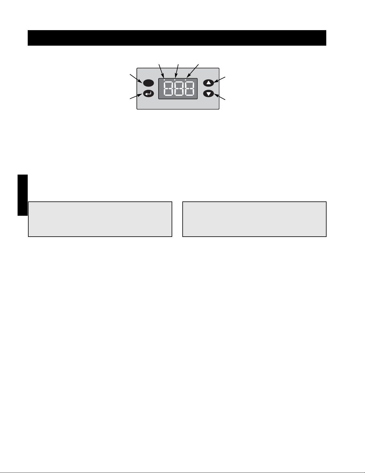
54
Operation - 4:1 Modulation & 8:1 Staged User Interface
Escape
Key
L1 L2 L3
Enter
Key
Up Key
Down
Key
Program Mode
Program mode allows the user to view the program menu and edit the factory default settings. To access
program mode and view the program menu press and hold the escape key for three seconds. While viewing the
program menu press the up and down keys to scroll through the menu options. To view the setting of the
selected menu option press the enter key. To edit the setting, press the up or down key while viewing the
setting. To save the setting and return to the program menu press the enter key. To return to the program menu
without saving the change, wait 10 seconds. To exit program mode from the program menu, wait 10 seconds.
Inlet Air Sensor (IAS)
The inlet air sensor monitors the temperature of the
inlet air. If the inlet air is above the sensor’s set point,
the inlet air sensor shuts off the furnace and
continues to supply the warm outside air. The inlet air
sensor is preset to the factory recommended 65ºF for
8:1 and 60ºF for 4:1.
Discharge Air Temperature (DtS)
The discharge air temperature setting is the
temperature that the unit will discharge. The
discharge air temperature is preset to the factory
recommended 70ºF. The actual discharge air
temperature is the default display.
Optional Freeze Protection (FtS)
If the discharge temperature drops below the freeze
temperature setting (default 45ºF) and remains below
the setting for longer than the time delay setting
(default 300 sec), the blower and burner will shut
down to prevent the discharge of cold air into the
building.
Optional Room Override (ROt)
When the room override function is triggered, the
discharge air temperature (70ºF default) is temporarily
changed to the room override setting (90ºF default).
When the room override function is released the
discharge air temperature returns to the default
temperature.
NOTE!
The enter key must be pressed to save any
changes made to a setting.
WARNING!
Changing the default settings will significantly
affect performance. Only change a setting after
reading and understanding this entire manual.
Outside Air Temperature (OAt)
To temporarily display the outside air temperature,
use the up and down keys until the display reads
“OAt,” then press the enter key.
Program Revision Number
To access the program revision number from the
default display, press the up or down keys until the
display reads F##, J## or I##. The two numbers
following the letter indicate the revision number. For
example, F12 indicates program F, revision twelve.
Operation
Page 55
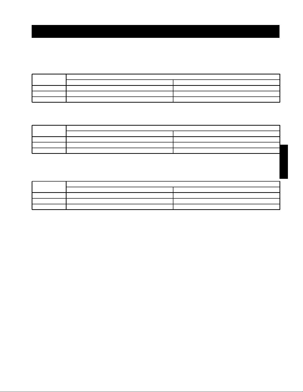
55
Operation - 4:1 Modulation & 8:1 Staged User Interface
Indicating Lights
Three indicating lights are located across the top of the display to indicate the status of the furnace.
4:1 Electronic Modulation
Light
On Off
L1 Call for Heat No Call for Heat
L2 Supply Fan On Supply Fan Off
L3 Freeze Protection Tripped Freeze Protection Satisfied
8:1 Staged Control (Single Furnace Units)
Light
On Blinking
L1 Call for Heat n/a
L2 n/a Furnace at High Fire
L3 Burner Locked Out Freeze Protection Tripped
8:1 Staged Control (Multi Furnace Units)
Light
On Blinking
L1 n/a n/a
L2 n/a Alarm
L3 Program Mode Saving New Settings
Operation
Page 56

56
Operation - 4:1 Electronic Modulation
Optional Exhaust fan switch (S1) manually closed
• Power passes through N.C. exhaust fan overload (ST2 O.L.) which is closed if exhaust fan (M2) has not
overloaded
• Power passes to exhaust fan starter (ST2)
• N.O. Exhaust fan starter contactor (ST2) is energized and closed
• Power passes to and energizes exhaust fan (M2)
Supply fan switch (S2) manually closed
• Power passes through N.C. field supplied fire contact (FSC)
• Power passes through optional N.O. exhaust fan contact (ST2) which is energized and closed
• Power passes through optional N.O. freeze protection contact (FZ1) which is closed if temperature has
remained above freeze protection set point
• Power passes to and energizes optional inlet damper (D1) which opens. Power also reaches optional return air
damper (D3) which will now modulate or open depending on control
• Power passes through damper limit switch (DL1) which is energized and closed if the inlet damper is open. It
may take several minutes for the damper to fully open and for the damper limit switch to close.
• Power passes through N.C. supply starter overload (ST1 O.L.) which is closed if supply fan has not overloaded
• Power reaches supply fan starter (ST1)
• N.O. supply fan starter (ST1) is energized and closed
• Power reaches and energizes supply fan (M1)
Heat switch (S3) manually closed
• Power passes through N.O. supply fan contact (ST1) which is energized and closed
• Power passes through call for heat relay (CH) which energizes and closes the N.O. call for heat contactor (Call
for Heat Contactor)
• The modulating controller (FX) compares the discharge temperature or space temperature to the set point and
sends a call for heat to the ignition controller (IC1)
Ignition Controller (IC1) Sequence of Operation
• The N.O. low air proving switch (PSL) is open
• The ignition controller (IC1) energizes the combustion blower (CM1)
• The N.O. low air proving switch (PSL) closes
• The ignition controller completes a 15 second pre-purge
• The main gas valve (MV1) is powered open
• 10 second trial for ignition period begins
• Igniter begins sparking
• The furnace will light at high fire
• When a flame is detected the igniter stops sparking
• The furnace will remain at high fire for 30 seconds
• The modulation controller (FX) will modulate the gas valve (MDV) and the combustion blower (CM1) as needed
between low fire and high fire
• The modulating controller (FX) will monitor the high pressure switch (PSH) and shut down the furnace if the
furnace is at high fire and the high pressure switch is not satisfied
High Fire – Low Fire Sequence of Operation
• The furnace lights at, and remains at high fire (100%) for 30 seconds
• If the discharge temperature is above the discharge temperature set point, and the furnace is not at low fire,
the modulation controller (FX) will modulate the gas valve (MDV) down until the discharge temperature equals
the discharge temperature setting.
• If the discharge temperature is below the discharge temperature set point, and the furnace is not at high fire,
the modulation controller (FX) will modulate the gas valve (MDV) up until the discharge temperature equals the
discharge temperature set point
Sequence of Operation
Operation
Page 57

57
Operation - 8:1 Staged Control
Optional Exhaust fan switch (S1) manually closed
• Power passes through N.C. exhaust fan overload (ST2 O.L.) which is closed if supply fan (M1) has not
overloaded
• Power passes to exhaust fan starter (ST2)
• N.O. Exhaust fan starter contactor (ST2) is energized and closed
• Power passes to and energizes exhaust fan (M2)
Supply fan switch (S2) manually closed
• Power passes through N.C. field supplied fire contact (FSC)
• Power passes through N.O. exhaust fan contact (ST2) which is energized and closed
• Power passes through optional N.O. freeze protection contact (FZ1) which is closed if temperature has
remained above freeze protection set point
• Power passes to and energizes inlet damper (D1) which opens. Power also reaches optional return air damper
(D3) which will now modulate or open depending on control
• Power passes through damper limit switch (DL1) which is energized and closed if the inlet damper is open. It
may take several minutes for the damper to fully open and for the damper limit switch to close.
• Power passes through N.C. supply starter overload which is closed if the supply fan has not overloaded
• Power reaches supply fan starter (ST1)
• N.O. supply fan starter (ST1) is energized and closed
• Power reaches and energizes supply fan (M1)
Heat switch (S3) manually closed
• Power passes through N.O. supply fan starter (ST1) which is energized and closed
• Power passes through call for heat relay (CH) which energizes and closes the N.O. call for heat contactor (CH)
• The modulating controller (FX) compares the discharge temperature or space temperature to the set point and
sends a call for heat to the ignition controller (IC1) when needed
Ignition Controller (IC1) Sequence of Operation
• The N.O. air proving switch (PSH#) is open
• The ignition controller (IC1) energizes the combustion blower (CM1)
• The N.O. air proving switch (PSH#) closes
• The ignition controller completes a 30 second pre-purge
• The main gas valve (MV1) is powered open
• 10 second trial for ignition period begins
• Igniter begins sparking
• The furnace will light
• The controller will choose which stage to light the furnace at, based on the discharge air temperature set point
and the outside air temperature
• When a flame is detected the igniter stops sparking
• The furnace will remain at high fire for 20 seconds
• The stage controller (FX) will stage the gas valves (MV#) as needed between low fire, high fire and off
• The stage controller (FX) will monitor the pressure switch (PSH#) and shut down the furnace if the furnace is at
high fire and the high pressure switch is not satisfied
• If the furnace is at low fire and the discharge temperature remains above the set point for more than six
minutes the furnace will shut down
Staging Sequence of Operation
• If the temperature is more than 1ºF below the discharge air temperature setting the furnace will stage up
• If the temperature is more than 1ºF above the discharge air temperature setting the furnace will stage down
• If the temperature is above the set temperature and the furnace is at low fire, the furnace will shut off
• The furnace will not stage consecutively in the same direction more than once every six minutes
• If the furnace is at high fire and the discharge air temperature setting is not satisfied, the furnace will remain at
high fire
• If the furnace is at low fire and the discharge air temperature setting is satisfied, the furnace will shut off
Sequence of Operation
Operation
Page 58

58
Operation - Recirculating / VAV Units
Manual Quadrant Damper Control
A manual quadrant damper in the return air flow controls the amount of recirculated air. This damper can be
adjusted by hand and locked in position for either 100% outside air or maximum recirculation air.
2-Position Damper Control
A 2-position spring return actuator is used to control the return air amounts. The damper moves from open to
closed. If power is cut to the unit, the damper will fail close. The volume of recirculation air is set in the factory
by baffles in the return air opening. These baffles should not be removed or adjusted in the field.
Potentiometer Control
A modulating spring return actuator is used to control the return air amounts. The damper moves from fully open
to fully closed. The amount of return air is determined by the position of a remote potentiometer.
Building Pressure Control
A modulating spring return actuator is used to control the return air amounts according to input from a pressure
sensing device. The recirculation damper moves from fully open to fully closed.
2-Speed Control
A 2-speed motor is used to control air volumes. The motor can be switched to low or high speed from a remote
control panel. One-half or one-third reduction motors are used.
Potentiometer Control
A variable frequency drive is controlled by input from a remote speed selector (potentiometer). This unit allows
easy manual adjustment of make-up air volumes.
Building Pressure Control
A variable frequency drive is controlled according to input from a pressure sensing device.
Variable Frequency Drives
For maintenance issues associated with the variable frequency drives, please consult the drive’s manual
supplied with the unit. The drives are programmed in the factory and should not need any adjustment during
installation and start-up. For kitchen applications, the drive is located in the kitchen, not in the unit.
Recirculation (Optional)
Variable Volume Operation (Optional)
Operation
Page 59

59
Operation - Economizer
NOTE!
Only models IG-HV and IGX-HV with options EC-1, 2, 3 or 4 use an economizer.
Option EC-1 (Outside Air Temperature Reference)
This option uses one dry bulb temperature sensor, field installed in the inlet of the unit. A second dry bulb
temperature sensor is factory installed in the discharge of the unit.
After a call for cooling, the outside air temperature is compared to the economizer set point. If the outside air
temperature is above the economizer set point, the economizer sends the dampers to the minimum outside air
position and calls for mechanical cooling. If the outside air temperature is between the economizer set point and
55ºF, the economizer sends the dampers to the 100% outside air position. If the outside air is less than 55ºF, the
economizer modulates the dampers to achieve a 55ºF mixed air temperature.
Option EC-2 (Outside Air Enthalpy Reference)
This option uses one enthalpy sensor field installed in the inlet of the unit. A dry bulb temperature sensor is
installed in the discharge of the unit.
After a call for cooling, the outside air enthalpy is compared to the field adjustable enthalpy changeover set
point. If the outside air enthalpy is less than the set point, the dampers will modulate to provide a 55ºF mixed air
temperature. If the outside air enthalpy is greater than the set point, the economizer sends the damper to the
minimum outside air position and sends a call for mechanical cooling.
Option EC-3 (Differential Temperature Control)
This option uses one dry bulb temperature sensor, field installed in the inlet of the unit. A second dry bulb
temperature sensor is factory installed in the discharge of the unit. A third dry bulb temperature sensor is field
installed in the return air duct.
After a call for cooling the economizer compares the outdoor and return air temperatures. If the outdoor air
temperature is greater than the return air dry bulb temperature, the economizer sends the dampers to the
minimum outside air position and sends a call for mechanical cooling. If the outside air temperature is less than
the return air temperature, the economizer will modulate the dampers to achieve a 55ºF mixed air temperature. If
the outside air temperature is less than the return air temperature, but a 55ºF mixed air temperature cannot be
achieved, the programmable room thermostat may call for mechanical cooling.
Option EC-4 (Differential Enthalpy Control)
This option uses one enthalpy sensor, field installed in the inlet of the unit. A second enthalpy sensor is factory
installed in the return air duct. A dry bulb temperature sensor is field installed in the discharge of the unit.
After a call for cooling the economizer compares the outdoor and return air enthalpies. If the outdoor air enthalpy
is greater than the return air enthalpy, the economizer sends the dampers to the minimum outside air position
and sends a call for mechanical cooling. If the outside enthalpy is less than the return air enthalpy, the
economizer will modulate the dampers to achieve a 55ºF mixed air temperature. If the outside enthalpy is less
than the return air temperature, but a 55ºF mixed air temperature cannot be achieved, the programmable room
thermostat may call for mechanical cooling.
Operation
Page 60

60
Operation - Water Wizard
Key Functions
Function Key
L1 L2 L3
Enter Key
Up Key
Down Key
Flow Test Mode
Activating flow test mode opens the supply solenoid and allows water to pass to the manual supply valve. To
activate flow test mode, press and hold the function key for one second (L3 will flash). To deactivate flow test
mode and allow the supply solenoid to close, press and hold the function key again for one second.
Program Mode
Program mode allows the user to view the program menu and edit the factory default settings. To access
program mode and view the program menu press and hold the enter key for three seconds. While viewing the
program menu press the up and down keys to scroll through the menu options. To view the setting of the
selected menu option press the enter key. To edit the setting, press the up or down key while viewing the
setting. To save the setting and return to the program menu press the enter key. To return to the program menu
without saving the change, wait 10 seconds. To exit program mode from the program menu, wait 10 seconds.
Drain Mode
Drain mode locks open the drain solenoid and drains the supply line between the supply solenoid and the
media. To activate drain mode simultaneously press the function and enter keys (L2 will light). To deactivate
drain mode and unlock the drain solenoid, simultaneously press the function and enter keys again.
Dry Bulb Temperature
The default display is the dry bulb temperature of the
outside air.
Wet Bulb Temperature
To view the wet bulb temperature, simultaneously
press and hold the up and down keys.
CAUTION!
The sump drain line must be clear and draining
to a safe location before using flow test mode.
NOTE!
The enter key must be pressed to save any
changes made to a setting.
WARNING!
Changing the default settings will significantly
affect performance. Only change a setting after
reading and understanding this entire manual.
CAUTION!
Be aware of the water level in the sump tank at
all times when using the flow test mode.
Indicating Lights
Three indicating lights are located across the top of the display to indicate the status of the Water Wizard.
Light Status
On Off
Blinking Blinking
(Long on, short off) (Short on, long off)
L1 Call For Cooling
No Call For
N/A N/A
Cooling
L2
Drain Solenoid Drain Solenoid
N/A N/A
Open Closed
L3 Cooling On Cooling Off
Supply Solenoid Flow Test Mode
Locked Closed Active
Operation
Page 61

61
Troubleshooting
Check Main Voltage
(See Blower Start-Up Step #1)
Main Disconnect (DS1) Off
(Turn Main Disconnect DS1 On)
Primary Fuses (FU6) or Secondary Fuses (FU7/8) Blown
(Replace Fuses)
Main Transformer (TR1) Defective
(Replace Transformer TR1)
24 VAC between
terminals R and X?
24 VAC between
terminals 8 and X?
Supply Fan Overload (ST1 OL) Tripped
(Reset and check motor amps, reference blower start-up #4)
24 VAC between
terminals 7 and X?
Damper Limit Switch (DL1) Holding
(Wait for actuator to open fully or adjust limit switch)
Damper Limit Switch Jumper Missing
(Install jumper, reference the units ladder diagram for terminals)
24 VAC between
terminals 6 and X?
Optional Exhaust Fan Interlocks (ST2-ST5) Open
(Correct/Replace)
Freeze Protection (FZ1) Tripped
(Reset)
24 VAC between
terminals G and X?
Supply Switch (S2) Off
(Turn Supply Switch S2 On)
Fire system contact (FSC) tripped
(Correct/Replace)
No
No
No
No
No
Yes
Yes
Yes
Yes
Note: At this time the supply contactor (ST1) should pull in passing
power to the supply motor and the blower should start.
Yes
Blower Does Not Operate
Broken Fan Belt
(Replace - Reference maintenance section)
Defective motor or capacitor
(Repair/Replace)
Blown Motor Fuse
(Replace)
One or more legs of 3 phase is out
(Restore missing legs)
Troubleshooting
Page 62

62
Troubleshooting
Motor Overamps
Air volume too high?
(Reference blower start-up step #5)
Adjust drives or increase external static pressure as
needed.
Motor horsepower too low?
Resize motor.
Motor voltage correct?
(Reference blower start-up step #1)
Provide proper power supply.
Blower rotation correct?
(Reference blower start-up step #2)
Reverse blower rotation.
Actual external static pressure
lower than design?
Adjust drives to reduce blower RPM.
No
No
Yes
Yes
Yes
Yes
No
Yes
No
No
Shorted windings in motor?
Replace motor.
Yes
Troubleshooting
Everything is working
properly, consult factory.
Yes
Page 63

63
Troubleshooting
Damper(s) not fully opened?
Adjust damper linkage(s), or replace faulty actuator(s).
Filters dirty or clogged
Clean or replace filters.
(Reference the maintenance section).
Blower speed too low?
Adjust drives as needed.
System static losses too high?
Reduce losses by improving ductwork.
Yes
Yes
Yes
Yes
No
No
No
No
No
Leaks in ductwork
Repair leaks.
Yes
Belt slipping
Replace or tighten belt.
Yes
Insufficient Airflow
Troubleshooting
Everything is working
properly, consult factory.
Yes
Page 64
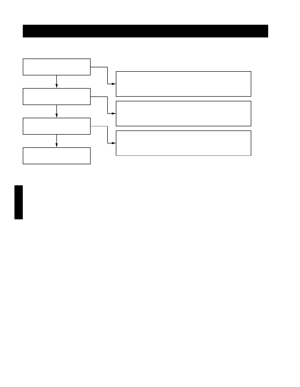
64
Troubleshooting
Blower speed too high?
Adjust drives as needed.
Insufficient external static
pressure?
Increase external static pressure.
Filters not in place?
Install filters.
Yes
Yes
Yes
No
No
Too Much Airflow
Troubleshooting
Everything is working
properly, consult factory.
No
Page 65
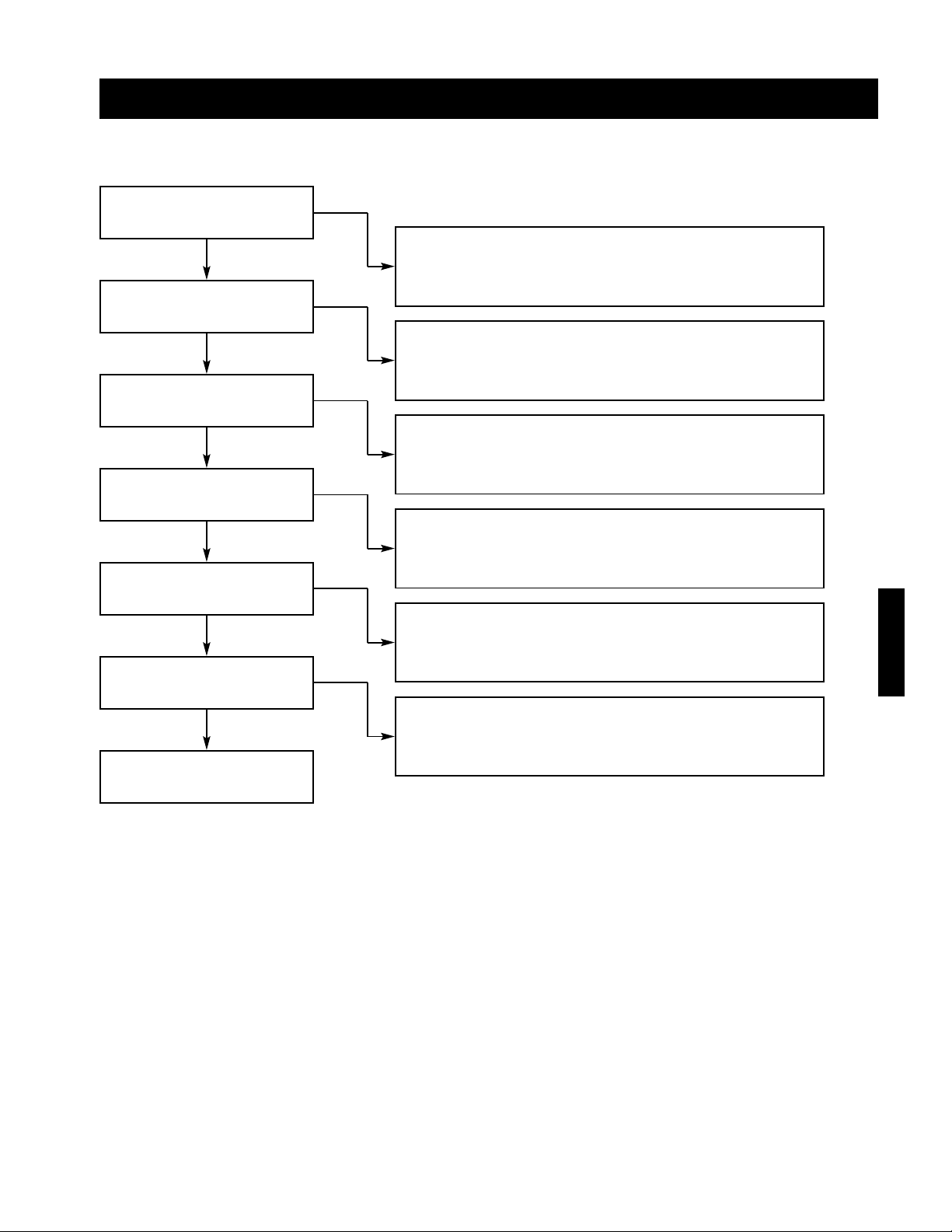
65
Troubleshooting
Excessive Noise or Vibration
Belts worn or loose?
Replace worn belts or tighten loose belts.
(Reference V-Belt drive maintenance in the maintenance section)
Wheel(s) rubbing on inlet?
Adjust wheel(s) or inlet.
Bearings worn or need
lubrication?
Replace worn bearings or lubricate bearings as needed.
(Reference bearing maintenance in the maintenance section)
Wheel(s) unbalanced?
Clean and/or balance wheel(s).
Sheaves aligned?
Align sheaves
(Reference V-Belt drive maintenance in the maintenance section)
Yes
Yes
No
Yes
Yes
No
No
No
Yes
Shipping fasteners removed from
blower vibration isolators.
Remove shipping fasteners from blower vibration isolators.
No
Yes
Troubleshooting
Everything is working
properly, consult factory.
No
Page 66
66
Troubleshooting
Single Stage or 2:1 Staged Furnace Will Not Light
Internal control failure?
(ignition controller LED on)
Ignition controller (IC1) failed.
(Replace ignition controller)
High limit (HLC#) open?
Discharge temperature was above high limit setting.
Wait for high limit to cool and reset.
24 VAC across A and X?
Discharge air selector (TS2) improperly set or faulty
Adjust setting (see staged start-up) or replace sensor
Furnace stage one contact (SC1-1) defective (stage only)
Replace furnace stage one contact
24 VAC across 20 and X?
Supply starter relay (ST1) defective
Replace supply starter relay
Optional inlet air sensor contact (TS1) open
Adjust inlet air sensor setting (refer to blower start-up)
Yes
No
No
Yes
No
Yes
Yes
24 VAC across W1 and X?
Heat switch (S3) open or not wired
Close or replace heat switch
No
Yes
24 VAC across R and X?
Main disconnect (DS1) open or defective
Close, repair or replace
Fusing (FU6 and/or FU8) blown
Replace blown fusing
Main transformer (TR1) fault
Replace main transformer
No
Yes
Airflow fault?
(ignition controller LED
blinking once)
Combustion blower (CM1) not functioning
Replace fusing (FU9), combusting blower or relay (CM1)
Air proving switch (PS2) defective.
Replace air proving switch
Yes
No
Ignition lockout?
(ignition controller LED
blinking three times)
Improper manifold pressure
Set high and low manifold pressure (refer to start-up)
Faulty spark rod or spark gap does not equal
1
⁄8 in.
Replace spark rod or adjust gap to 1⁄8 in.
Yes
No
Troubleshooting
Everything is working
properly, consult factory.
Yes
Page 67
67
Troubleshooting
Troubleshooting
2:1 Modulating Furnace Will Not Light
Internal control failure?
(ignition controller LED on)
Ignition controller (IC1) failed
(Replace ignition controller)
High limit (HLC#) open?
Discharge temperature was above high limit setting
Wait for high limit to cool and reset.
24 VAC across A and X?
Discharge air selector (TS2) improperly set or faulty
Adjust setting (see staged start-up) or replace sensor
Furnace stage one contact (SC1-1) defective (stage only)
Replace furnace stage one contact
24 VAC across 20 and X?
Supply starter relay (ST1) defective
Replace supply starter relay
Optional inlet air sensor contact (TS1) open
Adjust inlet air sensor setting (refer to blower start-up)
Yes
No
No
Yes
No
Yes
Yes
24 VAC across W1 and X?
Heat switch (S3) open or not wired
Close or replace heat switch
No
Yes
24 VAC across R and X?
Main disconnect (DS1) open or defective
Close, repair or replace
Fusing (FU6 and/or FU8) blown
Replace blown fusing
Main transformer (TR1) fault
Replace main transformer
No
Yes
Airflow fault?
(ignition controller LED
blinking once)
Combustion blower (CM1) not functioning
Replace fusing (FU9), combusting blower or relay (CM1)
Air proving switch (PS2) defective
Replace air proving switch
Yes
No
Ignition lockout?
(ignition controller LED
blinking three times)
Improper manifold pressure
Set high and low manifold pressure (refer to start-up)
Faulty spark rod or spark gap does not equal
1
⁄8 in.
Replace spark rod or adjust gap to 1⁄8 in.
Yes
No
Everything is working
properly, consult factory.
Yes
Page 68
68
24 VAC across terminals
X and A?
Internal high limit switch tripped
Allow discharge temperature to cool
Inlet air sensor contact open
Adjust inlet air sensor setting (refer to 4:1 modulation start-up)
Furnace controller (FX) defective
Replace furnace controller (FX)
24 VAC across 20 and X?
Supply starter relay (ST1) defective or not wired
Replace or wire supply starter relay
No
No
Yes
Yes
Call for heat relay (CH)
closed?
Call for heat relay (CH) defective
Replace call for heat relay (CH).
No
Yes
24 VAC across W1 and X?
Heat switch (S3) open or not wired
Close or replace heat switch
No
Yes
24 VAC across R and X?
Main disconnect (DS1) open or defective
Close, repair or replace
Fusing (FU6 and/or FU8) blown
Replace blown fusing
Main transformer (TR1) fault
Replace main transformer
No
Yes
Continues on next page...
4:1 Modulating Furnace Will Not Light
Troubleshooting
DT1 displayed on furnace
controller?
Discharge air sensor (TS2) not wired or defective
Wire or replace discharge air sensor (TS2)
Yes
No
OT1 displayed on furnace
controller?
Outdoor air sensor (TS6) not wired or defective
Wire or replace outdoor temperature sensor (TS6)
Yes
No
Blank screen on furnace
controller?
Furnace controller (FX) defective or not powered
Replace or wire furnace controller (FX)
Yes
No
Troubleshooting
Page 69
69
Internal control failure?
(ignition controller(s) LED on)
Ignition controller(s) (IC#) failed
Replace faulty ignition controller(s)
High limit switch (HLC#) open?
Discharge temperature was above high limit setting
Let cool then reset high limit.
Yes
Yes
No
Airflow fault?
(ignition controller LED
blinking once)
Pressure switch (PSL) failure
Repair or replace pressure switch (PSL)
Combustion blower (CM#) not functioning
Replace fusing (FU9), combustion blower or relay (CM#)
Yes
No
Ignition lockout?
(ignition controller LED
blinking three times)
Improper manifold pressure
Set high and low manifold pressure (refer to 4:1 mod. start-up)
Faulty spark rod or spark gap does not equal 1⁄8 in.
Replace spark rod or adjust gap to
1
⁄8 in.
Yes
No
120 VAC between terminals
101 and 102?
...continued from previous
page
Secondary fuse (FU7) blown
Replace secondary fuse (FU7)
Main transformer (TR1) defective
Replace main transformer (TR1)
Secondary transformer (TR2) defective
Replace secondary transformer (TR2)
A200 defective
Replace A200
Furnace controller (FX) defective
Replace furnace controller (FX)
No
No
Yes
24 VAC between terminals
1 and 2 on the A200
No
Yes
24 VDC between terminals
3 and 4 on the A200
No
Yes
10 VDC between terminals
5 and 6 on the A200
Everything is working
properly, consult factory.
No
Yes
4:1 Modulating Furnace Will Not Light
Troubleshooting
Troubleshooting
Page 70
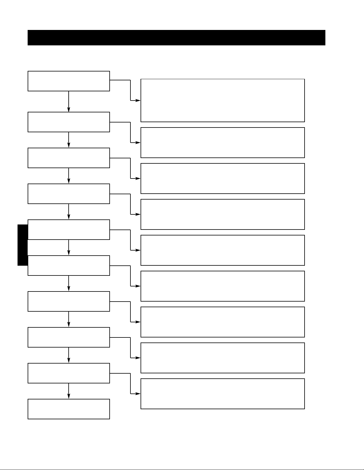
70
8:1 Staged Furnace Will Not Light
Troubleshooting
24 VAC across 20 and X?
Supply starter relay (ST1) defective or not wired
Replace or wire supply starter relay
No
Yes
Call for heat relay (CH)
closed?
Call for heat relay (CH) defective
Replace call for heat relay (CH)
No
Yes
24 VAC across W1 and X?
Heat switch (S3) open or not wired
Wire, close or replace heat switch
No
Yes
24 VAC across R and X?
Main disconnect (DS1) open or defective
Close, repaIr or replace main disconnect
Fusing (FU6 and/or FU8) blown
Replace blown fusing
Main transformer (TR1) defective
Replace main transformer
No
Yes
High limit switch (HLC#) open?
Discharge temperature above high limit setting
Let cool then reset high limit (HLC#)
Yes
No
DTI displayed on furnace
controller?
Discharge air sensor (TS2) not wired or defective
Wire or replace discharge air sensor (TS2)
Yes
No
OT1 displayed on furnace
controller?
Outdoor air sensor (TS6) not wired or defective
Wire or replace outdoor air sensor (TS6)
Yes
No
Blank screen on furnace
controller?
Furnace controller (FX) defective or not powered
Replace or wire furnace controller (FX)
Yes
No
With the combustion blower
(CM#) off, is the N.O. airflow
switch (PSH#) closed?
Continues on next page...
Airflow switch (PSH#) defective
Replace defective airflow switch (PSH#)
Yes
No
Troubleshooting
Page 71
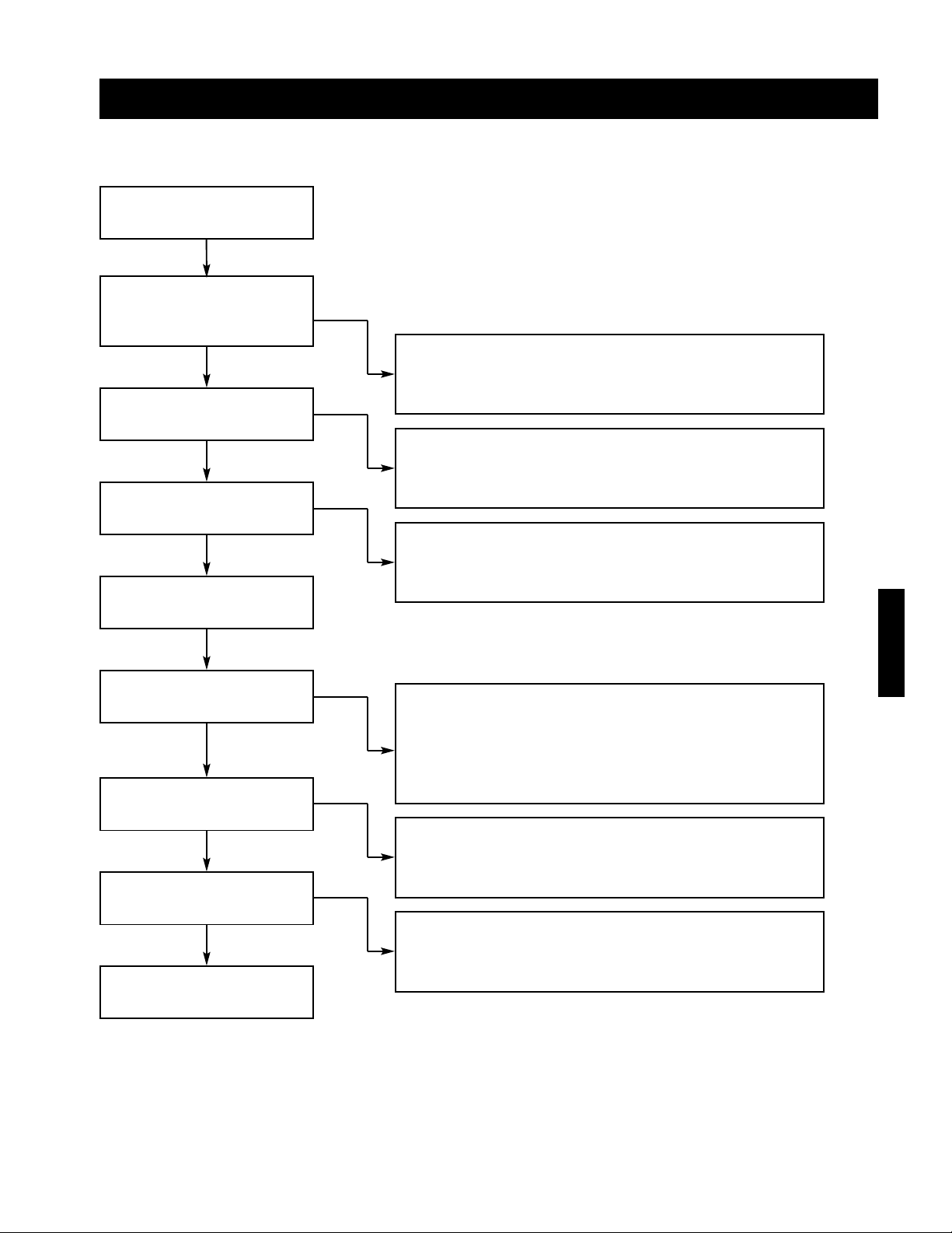
71
8:1 Staged Furnace Will Not Light
Troubleshooting
Internal control failure?
(ignition controller(s) LED on)
Ignition controller(s) (IC#) failed
Replace faulty ignition controller(s)
Yes
... continued from previous
page.
Does the combustion relay
(IR# or CR#) close?
Internal high limit tripped (temperature above set point)
Let temperatures cool
Internal inlet air sensor open
Adjust inlet air sensor setting (refer to 8:1 staged start-up)
Combustion relay (IR# or CR#) defective
Replace defective combustion relay (IR# or CR#)
No
Yes
Does the combustion blower
(CM#) run?
Combustion blower fuse (FU9) blown
Replace combustion blower fuse (FU9)
Combustion blower (CM#) defective
Replace defective combustion blower (CM#)
No
Yes
No
Ignition lockout?
(ignition controller LED
blinking three times)
No
Cycle power to the unit and
wait 30 seconds
Everything is working
properly, consult factory.
Improper manifold pressure
Set high and low manifold pressure (refer to 8:1 staged start-up)
Faulty spark rod or spark gap does not equal 1⁄8 in.
Replace spark rod or adjust gap to
1
⁄8 in.
Yes
Does the combustion blower
stop after 30 seconds of
operation?
Airflow switch (PSH#) defective
Replace defective airflow switch
Airflow relay (PSR) defective
Replace defective airflow relay (PSR)
Yes
No
With the combustion blower
(CM#) on for at least 30
seconds, is there 24 VAC
across X and A1 or A2?
Furnace controller (FX) defective
Replace furnace controller (FX)
No
Yes
Troubleshooting
Page 72
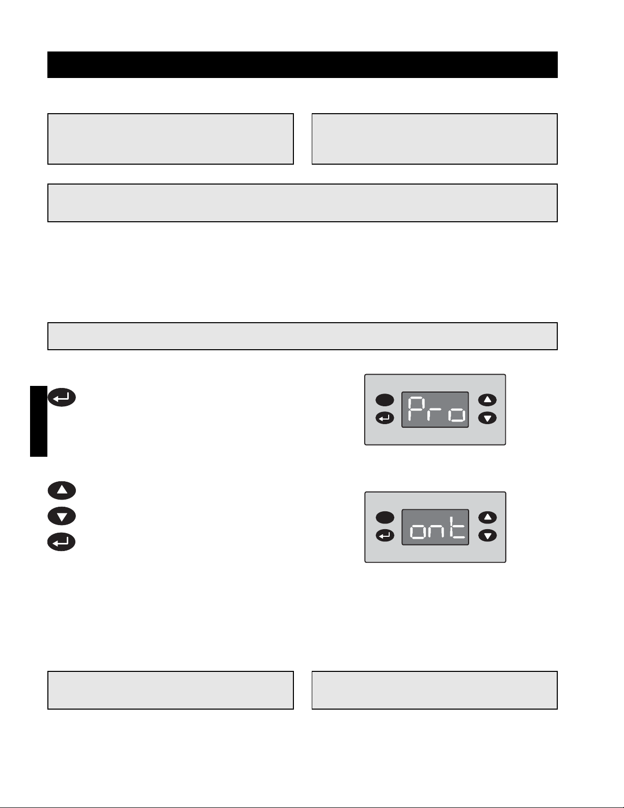
72
Troubleshooting
CAUTION!
Only proceed to steps two and three if step one does not correct the problem.
Step 2 Enter Program Mode
Press and hold the enter key for three
seconds to enter program mode. The
display will read “Pro” when program mode
is active.
Step 1 Adjust the Manual Supply Valve
Adjust the manual supply valve (refer to Water Wizard Start-Up Step #2). If the recommended water
pressure does not provide enough water, increase the pressure until the desired water supply is
achieved. If the recommended water pressure provides too much water, decrease the water pressure
until the desired water supply is achieved
Step 3 Adjust the On Time Factor
While in the program menu, use the up and
down keys to navigate through the menu
options until “ont” is displayed.
With “ont” displayed, press the enter key to
access the setting.
With the setting displayed, use the up and
down keys to adjust the setting as needed.
Increase the factor to increase the water
supply or decrease the factor to decrease
the water supply.
Press the enter key to save the new on
time factor and return to the program
menu.
Step 4 Exit Program Mode
After ten seconds of idle time the controller will automatically exit program mode.
NOTE!
If the water supply is too low, the media will
continuously appear dry.
NOTE!
Changing the on time factor by (1) will change
the water supply by approximately 3%.
NOTE!
If the water supply is too high, the media will be
saturated and excessive water will be draining
from the sump tank.
NOTE!
Some water drainage is desired to keep the media flushed, but it should be minimized to utilize the
Water Wizard.
IMPORTANT!
The enter key must be pressed to save the new
on time factor.
Water Wizard Water Supply
Troubleshooting
Page 73
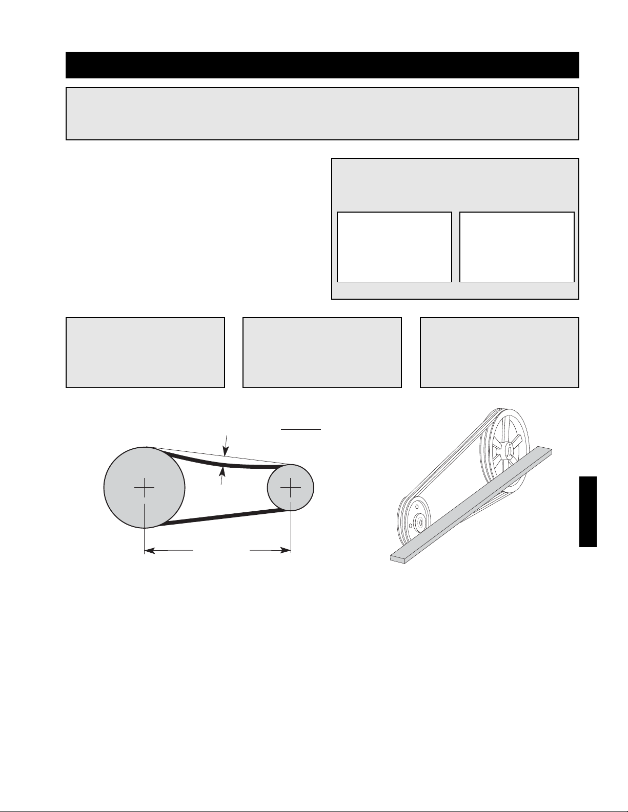
73
Maintenance - Routine
CAUTION!
Lock-out the gas and the electrical power to the unit before performing any maintenance or service
operations to this unit.
IMPORTANT!
Do not install new belts on worn
sheaves. If the sheaves have
grooves worn in them, they must
be replaced before new belts are
installed.
IMPORTANT!
Premature or frequent belt failures can be caused by
improper belt tension or misaligned sheaves.
Abnormally low belt tension
will cause squealing on
start-up, excessive belt
flutter, slippage and
overheated sheaves
Abnormally high belt tension
or drive misalignment will
cause excessive bearing
loads and may result in
failure of the fan and/or
motor bearings.
IMPORTANT!
When replacing V-belts on
multiple groove drives, all belts
should be changed to provide
uniform drive loading.
IMPORTANT!
Do not pry belts on or off the
sheave. Loosen belt tension until
belts can be removed by simply
lifting the belts off the sheaves.
V-Belt Drives
V-belt drives must be checked on a regular basis for
wear, tension, alignment and dirt accumulation.
Check the alignment by using a straight edge across
both sheaves as shown below.
Check the tension by measuring the deflection in the
belt as shown below.
Snow Accumulation
Clear snow away from roof mounted units. Keep the snow clear of the intake, access doors and any vent piping.
Maintenance
Belt Span
Deflection =
Belt Span
64
Page 74

74
Maintenance - Routine
Recommended Bearing Lubrication Schedule for Greenheck Fans
Relubrication Schedule in Months*
Bearings
The bearings for Greenheck fans are carefully
selected to match the maximum load and operating
conditions of the specific class, arrangement and fan
size. The instructions provided in this manual and
those provided by the bearing manufacturer will
minimize any bearing problems.
Fan RPM Bearing Bore Size (inches)
1/2 - 1 1 1/8 - 1 1/2 1 5/8 - 1 7/8 1 15/16 - 2 3/16 2 7/16 - 3
25066666
50066654
75065433
1000 53211
1250 53211
1500 52110.5
2000 5 1 1 0.5 0.25
* Suggested initial greasing interval is based on 12 hour per day operation and 150°F maximum
housing temperature. For continuous (24 hour) operation, decrease greasing interval by 50%
- If extended grease lines are present, relubricate while in operation, only without endangering
personnel.
- For ball bearings (operating) relubricate until clean grease is seen purging at the seals. Be sure not
to unseat the seal by over lubricating.
- For ball bearings (idle) add 1-2 shots of grease up to 2 inch bore size, and 4-5 shots above 2 inch
bore sizes with a hand grease gun.
- For roller bearings add 4 shot of grease up to 2 inch bore size, and 8 shots for 2 inch - 5 inch
bore size with a hand grease gun.
- Adjust relubrication frequency based on condition of purged grease.
- A high quality lithium based grease conforming to NLGI Grade 2 consistency, such as those listed
below should be used:
Mobil 532 Texaco Multifak #2 B Shell Alavania #2
Mobilux #2 Texaco Premium #2 Exxon Unirex N2
WARNING!
Lubricate bearings prior to periods of extended
shutdowns or storage and rotate shaft monthly
to aid in corrosion prevention. If the fan is
stored more than three months, purge the
bearings with new grease prior to start-up.
Motors
Motor maintenance is generally limited to cleaning
and lubrication (where applicable).
Cleaning should be limited to exterior surfaces only.
Removing dust and grease build-up on the motor
assures proper motor cooling.
Motors supplied with grease fittings should be
greased in accordance with the manufacturer’s
recommendations.
CAUTION!
Do not allow water or solvents to enter the motor
or bearings. Motors and bearings should never
be sprayed with steam, water or solvents.
WARNING!
Greasing motors is only intended when fittings
are provided. Many motors are permanently
lubricated, requiring no additional lubrication.
Wheels
Wheels require little attention when moving clean air.
Occasionally oil and dust may accumulate on the
wheel causing imbalance. When this occurs the
wheel and housing should be cleaned to assure
proper operation.
Maintenance
Page 75

75
Maintenance - Routine
Filters
Filter maintenance is generally limited to cleaning and
replacement.
If aluminum mesh filters are installed, they can be washed in
warm soapy water.
An adhesive spray can be added to aluminum mesh filters to
increase their efficiency.
If disposable filters are installed, they can be checked by
holding up to a light source. If light cannot pass through the
filter, it should be replaced.
IMPORTANT!
When reinstalling filters be sure to install
them with the airflow in the correct
direction. An airflow direction arrow is
located on the side of the filters.
IMPORTANT!
Replacement filters should be from the
same manufacturer and the same size as
the original filters provided with the unit.
Evaporative Coolers
The media should be periodically brushed lightly with a soft
bristle brush in an up and down motion while flushing with
water. This aids in reducing the amount of mineral build-up.
For large amounts of mineral build-up, clean or replace the
media and increase the water bleed-off or flush rate.
The cooling media has a useful life of 3 to 5 years depending
on the water quality and the bleed-off or flush rate.
Leaving Air
Entering Air
45°
15°
IMPORTANT!
Replacement media should be from the same
manufacturer and be the same size as the original
media provided with the unit.
IMPORTANT!
When reinstalling the evaporative media,
make sure that it is installed correctly.
Reference the drawing shown below.
Cooling Coils
Inspect the coil for signs of corrosion and/or leaks. Repair
any leaks as required.
Inspect the coil’s surface for foreign material. If the coil
surface needs cleaning, clean the coil from the leaving airside so that foreign material will be washed out of the coil
rather than pushed farther in.
Inspect and clean the drain pan to prevent the growth of
algae and other organisms.
IMPORTANT!
Be sure to read and follow the
manufacturer’s recommendations before
using any cleaning fluid.
WARNING!
Repair and replacement of the coil and
the connecting piping, valves, etc.,
should be performed by a qualified
individual.
Chilled Water Coils
Test the circulating fluid for sediment, corrosive products,
biological contaminants and make the necessary corrective
measures.
Maintain adequate fluid velocities and proper filtering of the
fluid.
If automatic air vents are not utilized, periodic venting of the
coil is recommended to remove accumulated air.
CAUTION!
Caution should be used to avoid injury
when venting the coil. High pressure
and/or high temperature fluids can cause
serious injuries.
Maintenance
Page 76

76
Maintenance - Fall
Evaporative Coolers
The water should be shut off and all the lines drained when the outside temperature drops below 45°F.
Remove drain plugs for the winter.
Clean all interior parts of any mineral deposits or foreign materials that may have built-up during the cooling
season.
Replace any worn or non-functioning parts.
Gas Line
Remove the drip leg and clean any liquid or debris that may have accumulated. Once the drip leg is cleaned,
reattach it.
Vent Piping
Remove any debris from the drip legs on the combustion air and exhaust pipes.
Burners and Orifices
Before each heating season, examine the burners and gas orifices to make sure they are clear of any debris such
as spider webs, etc. Clean burner as follows:
• Turn off both electrical and gas supplies to the unit.
• Disconnect union between manifold and gas valve.
• Remove manifold and burner assembly.
• Inspect and clean orifices and burners as necessary. Avoid using any hard or sharp instruments which
could cause damage to the orifices or burners.
- Remove any soot deposits from the burner with a wire brush.
- Clean the ports with an aerosol degreaser or compressed air.
- Wipe the inside of the burner clean. Cleaning the burner with a degreaser will slow the future build-up
of dirt.
• Before reinstalling the burner assembly, look down the heat exchanger tubes to make sure they are
clear of any debris.
• Reinstall manifold and burner assembly, reconnect wire leads and gas supply piping.
• Turn on the electrical power and gas supply.
• Follow the start-up procedure to light the burners and verify proper operation.
Heat Exchanger
The heat exchanger should be checked annually for cracks. If a crack is detected, the heat exchanger should be
replaced before the unit is put back into operation. Also, airflow across the heat exchanger should be checked to
make sure the blower is operating properly.
Flue Collector Box
The flue passageway and flue collector box should be inspected prior to each heating season and cleared of any
debris.
Electrical Wiring
The electrical wiring should be checked annually for loose connections or deterioration.
Replacement Parts
When ordering replacement parts, include the complete unit model number and serial number listed on the unit
rating plate.
CAUTION!
Lock-out the gas and the electrical power to the unit before performing any maintenance or service
operations to this unit.
Maintenance
Page 77

77
Maintenance - Log
Job Information
Job Name: ____________________________________
Address: ______________________________________
City: ________________ State: ________ Zip:_______
Phone: __________________ Fax:_________________
Contact Person: _______________________________
Service Organization: _____________________________
Address: ________________________________________
City: ________________ State: ________ Zip: _________
Phone: __________________ Fax: ___________________
Work Done By:___________________________________
Name Plate Information
Model:________________________________________
Volts: ___________ Hertz: __________ Phase: ______
Amps: __________________ Mark: ________________
Supply hp: _____________ Exhaust hp: ___________
Serial Number:_________________________________
Motor Voltage:
Motor Amperage:
Fan rpm:
Maintenance
Field Start-Up Documentation
Actual Voltage: Hertz: Phase:
Actual Amperage:
Blower Rotation
Air Volume Design
cfm
Actual
cfm
High Fire Manifold Pressure:
Low Fire Manifold Pressure:
Date Time Notes:
Maintenance
Page 78

78
Date Time Notes:
Maintenance - Log
Maintenance
Page 79

79
Date Time Notes:
Maintenance - Log
Maintenance
Page 80
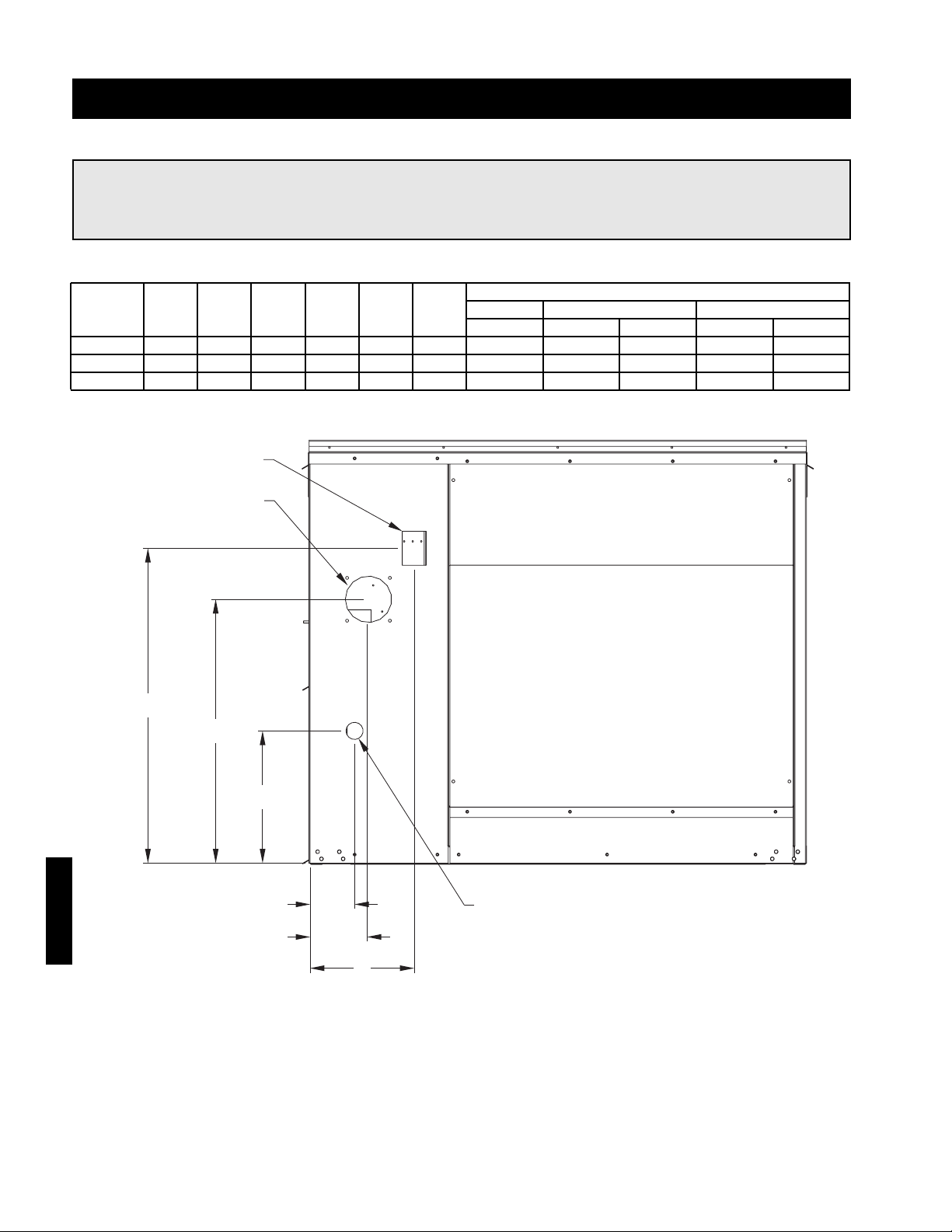
80
Reference - Venting Connection Location
Flue Connection Size (Diameter)
IG
A B C D E F Standard Non-Concentric Concentric
Housing
Exhaust Exhaust Intake Exhaust Intake
10 3.89 5.12 9.12 11.59 23.11 27.58 4.0 4.0 4.0 4.0 6.0
20 3.91 3.89 7.89 11.62 25.34 32.27 6.0 6.0 6.0 6.0 8.0
30 3.91 3.89 7.89 11.62 25.34 32.27 6.0 6.0 6.0 6.0 8.0
Model IG
Discharge End
NOTE!
All dimensions are in inches. Dimensions B and E are not needed for standard venting. A round
adapter should be used for the exhaust connection.
Reference
Exhaust Outlet
Combustion Air Inlet
F
E
D
A
B
C
3/4" Gas Connection
Page 81
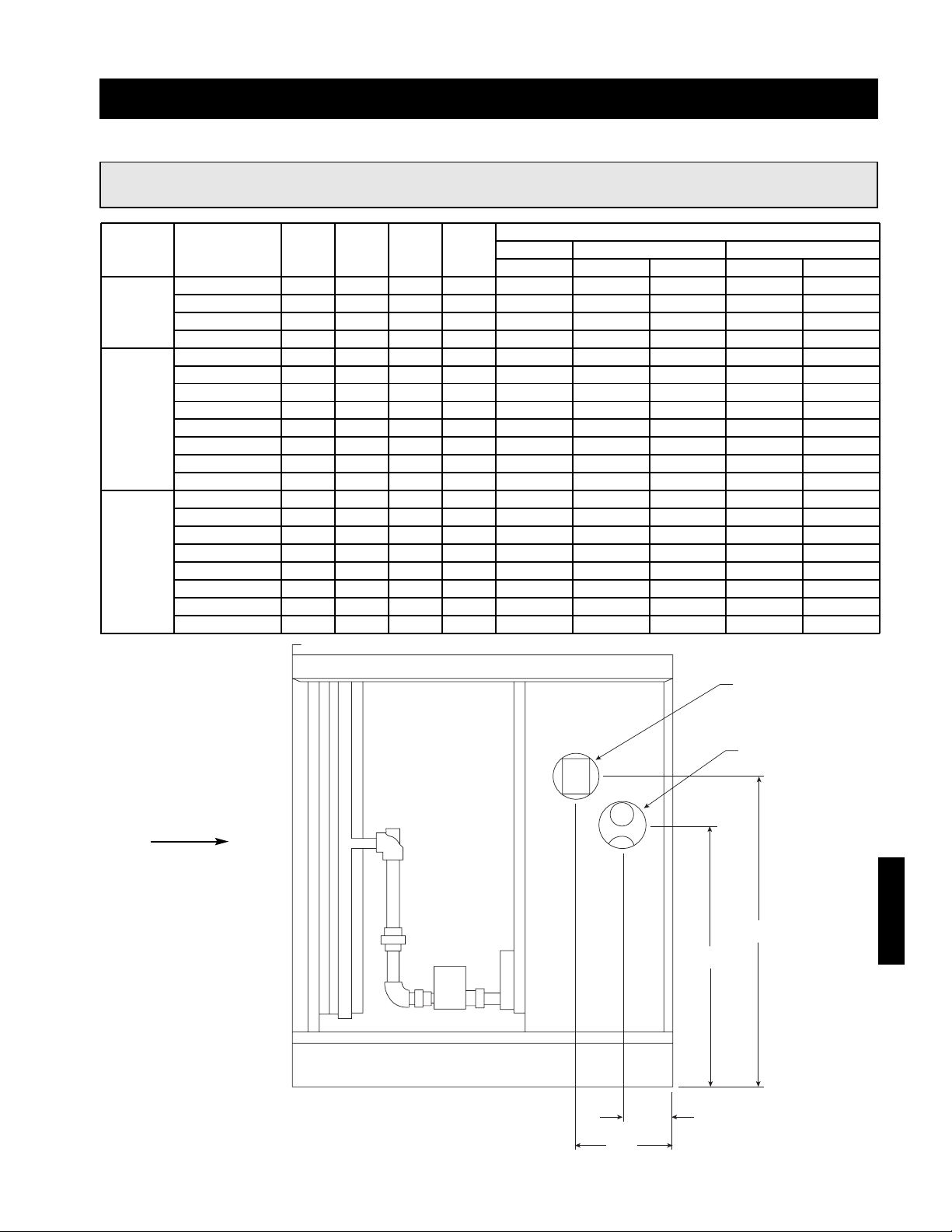
81
Reference - Venting Connection Location
Exhaust Air Outlet
Combustion Air Intake
C
D
A
B
Flue Connection Size (Diameter)
Housing Furnace Size
A B C D Standard Non-Concentric Concentric
IGX (MBH)
Exhaust Exhaust Intake Exhaust Intake
100 4.45 8.45 23.43 27.90 4.0 4.0 4.0 4.0 6.0
12
150 4.45 8.45 23.43 27.90 4.0 4.0 4.0 4.0 6.0
200 5.64 9.64 23.97 30.90 6.0 6.0 6.0 6.0 8.0
250 5.64 9.64 23.97 30.90 6.0 6.0 6.0 6.0 8.0
150 4.45 8.45 29.38 33.85 4.0 4.0 4.0 4.0 6.0
200 5.67 9.67 24.97 31.90 6.0 6.0 6.0 6.0 8.0
250 5.67 9.67 24.97 31.90 6.0 6.0 6.0 6.0 8.0
22
300 5.67 9.67 24.97 31.90 6.0 6.0 6.0 6.0 8.0
350 5.67 9.67 19.01 25.94 6.0 6.0 6.0 6.0 8.0
400 5.67 9.67 19.01 25.94 6.0 6.0 6.0 6.0 8.0
500 5.67 9.67 24.97 31.90 6.0 6.0 6.0 6.0 8.0
600 5.67 9.67 24.97 31.90 6.0 6.0 6.0 6.0 8.0
350 5.96 9.71 28.31 35.24 6.0 6.0 6.0 6.0 8.0
400 5.96 9.71 28.31 35.24 6.0 6.0 6.0 6.0 8.0
500 5.96 9.71 28.31 35.24 6.0 6.0 6.0 6.0 8.0
32
600 5.96 9.71 28.31 35.24 6.0 6.0 6.0 6.0 8.0
700 5.96 9.71 28.31 35.24 6.0 6.0 6.0 6.0 8.0
800 5.96 9.71 28.31 35.24 6.0 6.0 6.0 6.0 8.0
1050 5.96 9.71 28.31 35.24 6.0 6.0 6.0 6.0 8.0
1200 5.96 9.71 28.31 35.24 6.0 6.0 6.0 6.0 8.0
Model IGX
Airflow
NOTE!
All dimensions are in inches. Dimensions A and C are not needed for standard venting.
Reference
Page 82
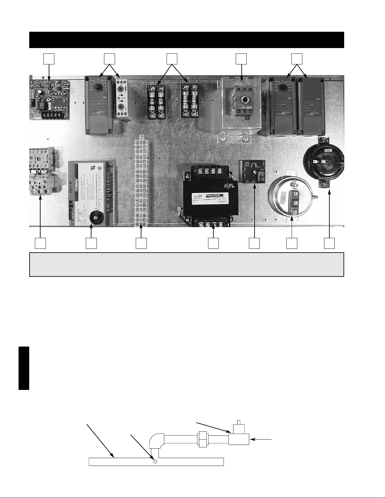
82
Reference - Model IG (Single or 2 Stage)
3
⁄4 inch Gas Supply
Connection
Staged Gas
Valve
Manifold
Gas Pressure
Test Port
Reference
1
6 7 8 9 10 11 12
2 3 4 5
1. Building Freeze Protection - Prevents the discharge of cold air into the building
2. Evaporative Cooling Controls (Optional) - Controls the evaporative cooler.
3. Fusing - Provides 24 VAC fusing for controls and fusing for the combustion blower.
4. Main Disconnect - Provides single point power connection to the unit.
5. Stage Controller - Provides single or two stage control of the furnace.
6. Motor Starter(s) - Magnetic contact(s) for starting motor(s). Comes standard with electronic overload,
auxiliary contact(s) optional.
7. Ignition Controller - Controls the ignition of the furnace. Maintains safe operation of the furnace.
8. Terminal Strip - Provides easy, number coded wiring of the control.
9. Main Transformer - Provides 24 VAC for controls.
10. Time Delay - Temporarily runs the combustion blower after the furnace has shut down (post-purge).
11. Dirty Filter Switch - Switch trips when filter are dirty and pressure loss is higher than set point.
12. Airflow Switch - Monitors the airflow inside the heat exchanger.
13. Inlet Air Sensor (not shown) - Shuts down furnace when the outside air is above the set point.
14. Grounding Lugs (not shown) - Completes electrical circuit.
15. Heat/Cool Relay (not shown) - Passes power to the furnace or cooling controls.
NOTE!
This is a typical blower control center, the control center in your unit may be different. Reference the
ladder diagram on the inside of the control center door for a unit specific wiring diagram.
Page 83
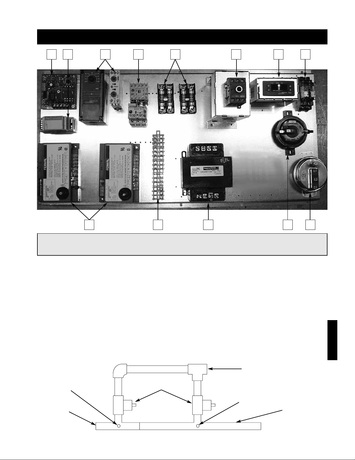
83
Reference - Model IG (8:1 Staged)
Large
Manifold
Small
Manifold
Gas Pressure
Test Port
Gas Pressure
Test Port
3
⁄4 inch Gas Supply
Connection
Staged Gas
Valves
Reference
1. Building Freeze Protection - Prevents the discharge of cold air into the building.
2. Input Converter - Receives and converts signal from building management system.
3. Evaporative Cooling Controls (Optional) - Controls the evaporative cooler.
4. Motor Starter(s) - Magnetic contact(s) for starting motor(s). Comes standard with electronic overload,
auxiliary contact(s) optional.
5. Fusing - Provides 24 VAC fusing for controls and fusing for the combustion blower.
6. Main Disconnect - Provides single point power connection to the unit.
7. Stage Controller - Provides 8-stage control of the furnace.
8. Relays - Call for heat and airflow switch relays.
9. Ignition Controllers - Controls the ignition of the furnace. Maintains safe operation of the furnace.
10. Terminal Strip - Provides easy, number coded wiring of the control.
11. Main Transformer - Provides 24 VAC for controls.
12. Airflow Switch - Monitors the airflow inside the heat exchanger.
13. Dirty Filter Switch - Switch trips when filters are dirty and pressure loss is higher than set point.
14. Grounding Lugs (not shown) - Completes electrical circuit.
1
9
2
11
12 13
4
10
3
5
6 7
8
NOTE!
This is a typical blower control center, the control center in your unit may be different. Reference the
ladder diagram on the inside of the control center door for a unit specific wiring diagram.
Page 84
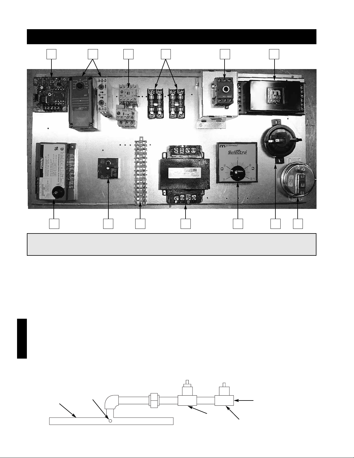
84
Reference - Model IG (2:1 Modulating)
Manifold
Gas Pressure
Test Port
3
⁄4 inch Gas Supply
Connection
Staged Gas
Valve
Modulating
Gas Valve
Reference
1
7 9 10 11
3
8 12 13
2 4 5 6
1. Building Freeze Protection - Prevents the discharge of cold air into the building.
2. Evaporative Cooling Controls (Optional) - Controls the evaporative cooler.
3. Motor Starter(s) - Magnetic contact(s) for starting motor(s). Comes standard with electronic overload,
auxiliary contact(s) optional.
4. Fusing - Provides 24 VAC fusing for controls and fusing for the combustion blower.
5. Main Disconnect - Provides single point power connection to the unit.
6. Amplifier - Controls the modulating valve based on input from the temperature selector and the
discharge air sensor.
7. Ignition Controller - Controls the ignition of the furnace. Maintains safe operation of the furnace.
8. Time Delay - Temporarily runs the combustion blower after the furnace has shut down (post-purge).
9. Terminal Strip - Provides easy, number coded wiring of the control.
10. Main Transformer - Provides 24 VAC for controls.
11. Temperature Selector - Allows the user to adjust the discharge air temperature.
12. Airflow Switch - Monitors the airflow inside the heat exchanger.
13. Dirty Filter Switch - Switch trips when filters are dirty and pressure loss is higher than set point.
14. Inlet Air Sensor (not shown) - Shuts down furnace when the outside air is above the set point.
15. Grounding Lugs (not shown) - Completes electrical circuit.
NOTE!
This is a typical blower control center, the control center in your unit may be different. Reference the
ladder diagram on the inside of the control center door for a unit specific wiring diagram.
Page 85
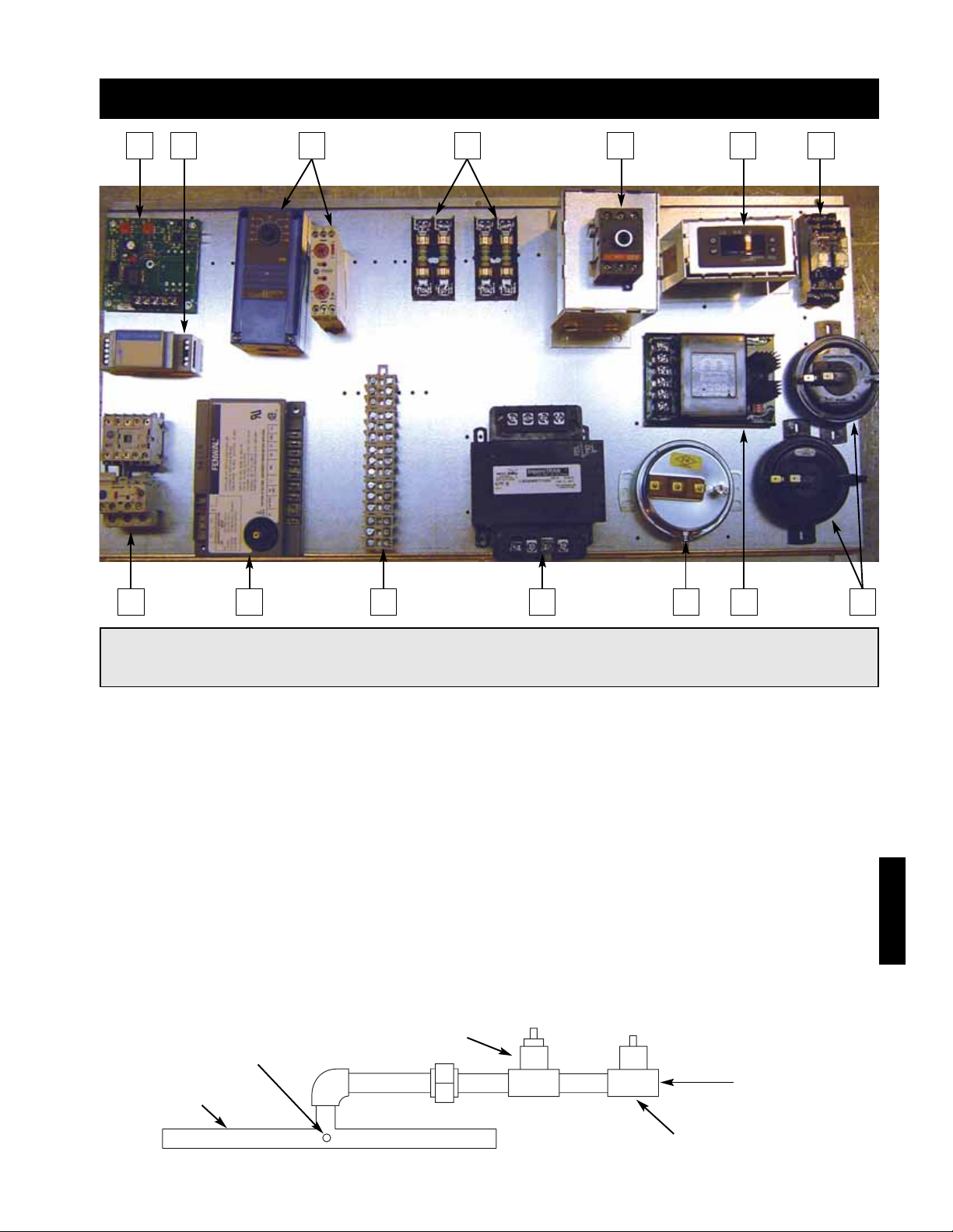
85
Reference - Model IG (4:1 Modulating)
Manifold
Gas Pressure
Test Port
3
⁄4 inch Gas Supply
Connection
Staged Gas
Valve
Modulating
Gas Valve
Reference
1 2
11 12 13 14108 9
3
4
5 6
7
1. Building Freeze Protection - Prevents the discharge of cold air into the building.
2. Input Converter - Receives and converts signal from building management system.
3. Evaporative Cooling Controls (Optional) - Controls the evaporative cooler.
4. Fusing - Provides 24 VAC fusing for controls and fusing for the combustion blower.
5. Main Disconnect - Provides single point power connection to the unit.
6. Modulation Controller - Provides 4:1 modulating turndown control of the furnace.
7. Relays - Call for heat and pressure switch relays.
8. Motor Starter(s) - Magnetic contact(s) for starting motor(s). Comes standard with electronic overload,
auxiliary contact(s) optional.
9. Ignition Controller - Controls the ignition of the furnace. Maintains safe operation of the furnace.
10. Terminal Strip - Provides easy, number coded wiring of the control.
11. Main Transformer - Provides 24 VAC for controls.
12. Dirty Filter Switch - Switch trips when filters are dirty and pressure loss is higher than set point.
13. Amplifier - Controls the modulating valve based on input from the temperature selector and the
discharge air sensor.
14. Airflow Switches - Monitors the airflow inside the heat exchanger.
15. Grounding Lugs (not shown) - Completes electrical circuit.
NOTE!
This is a typical blower control center, the control center in your unit may be different. Reference the
ladder diagram on the inside of the control center door for a unit specific wiring diagram.
Page 86
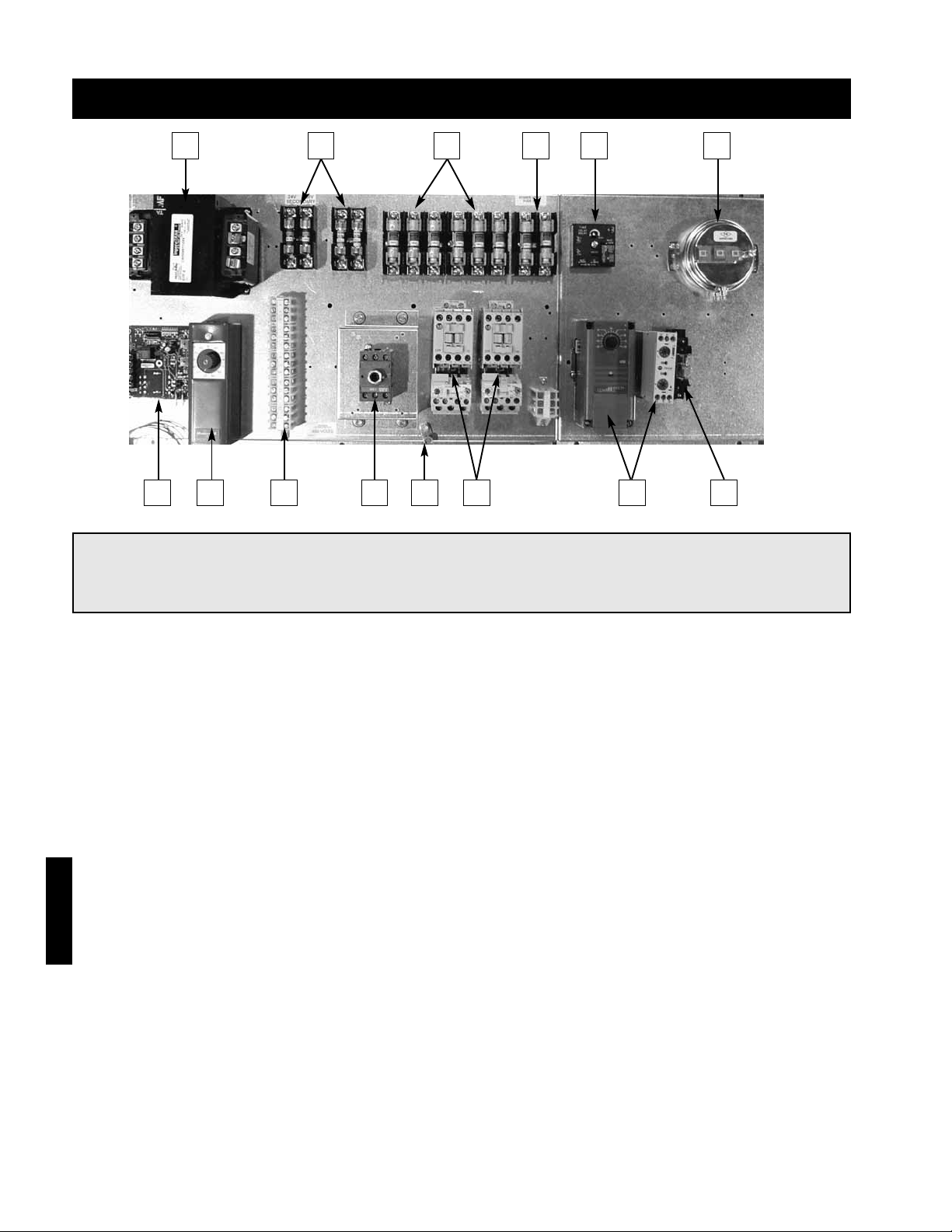
86
Reference - Model IGX (Blower Control Center)
1 2 3 4 5 6
7 8 9 10 11 12 13 14
1. Main Transformer - Provides 24 VAC for controls.
2. Control Fusing - Provides 24 VAC fusing for controls.
3. Blower Fusing - Provides fusing for supply and optional exhaust blower(s).
4. Combustion Blower Fusing - Provides fusing for combustion blower(s).
5. Solid Fuel Time Delay - Temporarily runs blower(s) after the unit has been manually shutdown.
6. Dirty Filter Switch - Switch trips when filters are dirty and pressure loss is higher than set point.
7. Building Freeze Protection - Shuts down blower when discharge air temperature drops below set point
and remains below set point for longer than the time delay. Prevents the discharge of cold air into the
building.
8. Inlet Air Sensor - Shuts down furnace when the outside air is above the set point.
9. Terminal Strip - Provides easy, number coded wiring of the control.
10. Main Disconnect - Provides single point power connection to the unit.
11. Grounding Lugs - Completes electrical circuit.
12. Motor Starter(s) - Magnetic contact(s) for starting motor(s). Comes standard with electronic overload,
auxiliary contact(s) optional.
13. Evaporative Cooling Controls (Optional) - Controls the evaporative cooler.
14. Heat/Cool Relay - Passes power to the furnace or cooling controls.
NOTE!
This is a typical blower control center, the control center in your unit may be different. Reference the
ladder diagram on the inside of the control center door for a unit specific wiring diagram.
Reference
Page 87
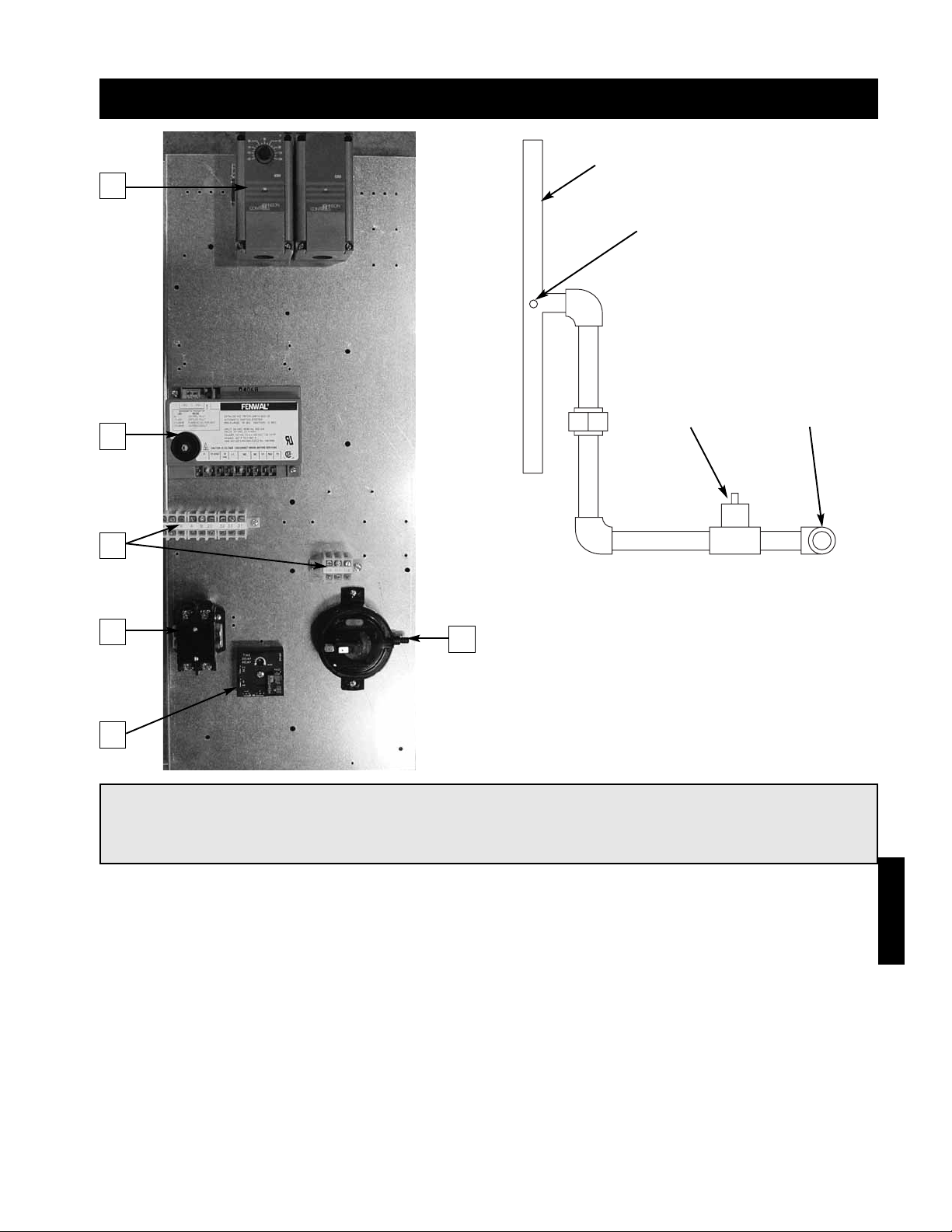
87
Reference - Model IGX (Single or 2 Stage)
Gas Pressure
Test Port
3
⁄4 inch Gas Supply
Connection
Staged Gas
Valve
Manifold
1
2
3
4
6
5
1. Stage Control - Provides single or 2-stage control of the furnace.
2. Ignition Controller - Controls the ignition of the furnace. Maintains safe operation of the furnace.
3. Terminal Strip - Provides easy, number coded wiring of the control.
4. Combustion Blower Contact - Passes power to the combustion blower.
5. Airflow Switch - Monitors the airflow inside the heat exchanger.
6. Time Delay - Temporarily runs the combustion blower after the furnace has shut down (post-purge).
NOTE!
This is a typical furnace control center, the control center in your unit may be different. Reference the
ladder diagram on the inside of the control center door for a unit specific wiring diagram.
Reference
Page 88
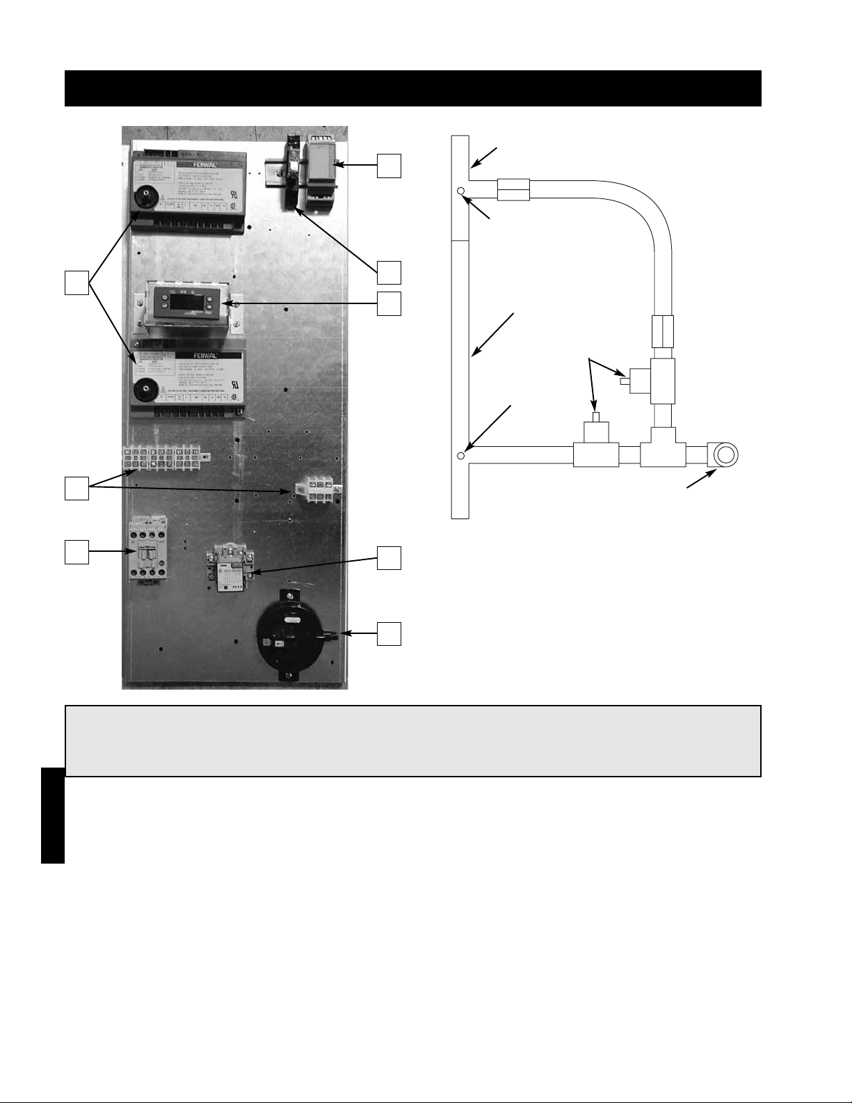
88
Reference
Reference - Model IGX (8:1 Staged)
Large
Manifold
Small Manifold
Gas Pressure
Test Port
Gas Pressure
Test Port
3
⁄4 inch Gas Supply
Connection
Staged Gas
Valve
1
2
3
4
5
6
7
8
1. Input Converter - Receives and converts signal from a building management system.
2. Call for Heat Relay - Passes power to furnace controls when there is a call for heat.
3. Ignition Controllers - Controls the ignition of the furnace. Maintains safe operation of the furnace.
4. Stage Controller - Provides 8-stage control of the furnace.
5. Terminal Strip - Provides easy, number coded wiring of the control.
6. Combustion Blower Contact - Passes power to the combustion blower.
7. Pressure Switch Relay - Functions as a relay for the pressure switch.
8. Airflow Switch - Monitors the airflow inside the heat exchanger.
NOTE!
This is a typical furnace control center, the control center in your unit may be different. Reference the
ladder diagram on the inside of the control center door for a unit specific wiring diagram.
Page 89
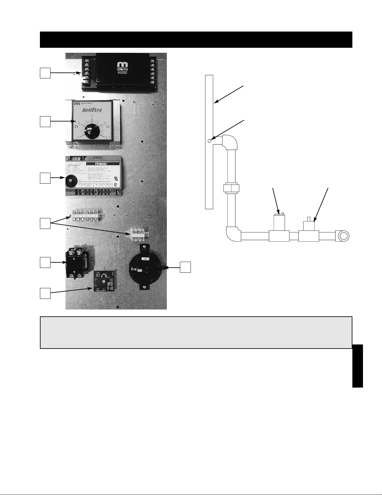
89
Reference - Model IGX (2:1 Modulation)
Gas Pressure
Test Port
Modulating
Gas Valve
Staged Gas
Valve
Manifold
1
2
3
4
5
6
7
1. Amplifier - Controls the modulating valve based on input from the temperature selector and the
discharge air sensor.
2. Temperature Selector - Allows the user to adjust the discharge air temperature.
3. Ignition Controllers - Controls the ignition of the furnace. Maintains safe operation of the furnace.
4. Terminal Strip - Provides easy, number coded wiring of the control.
5. Combustion Blower Contact - Passes power to the combustion blower.
6. Airflow Switch - Monitors the airflow inside the heat exchanger.
7. Time Delay - Temporarily runs the combustion blower after the furnace has shut down (post-purge).
NOTE!
This is a typical furnace control center, the control center in your unit may be different. Reference the
ladder diagram on the inside of the control center door for a unit specific wiring diagram.
Reference
Page 90

90
Reference - Model IGX (4:1 Modulation)
Gas Pressure
Test Port
Modulating
Gas Valve
Staged Gas
Valve
Manifold
1
2
3
4
6
7
8
5
1. Amplifier - Controls the modulating valve based on input from the temperature selector and the
discharge air sensor.
2. Combustion Blower Relays - Pass power to the variable speed combustion blower.
3. Transformer - Provides 24V power to the amplifier.
4. Modulation Controller - Provides 4:1 modulation control of the furnace.
5. Ignition Controller - Controls the ignition of the furnace. Maintains safe operation of the furnace.
6. Terminal Strip - Provides easy, number coded wiring of the control.
7. Input Converter - Receives and converts signal from a building management system.
8. Airflow Switch - Monitors the airflow inside the heat exchanger.
NOTE!
This is a typical furnace control center, the control center in your unit may be different. Reference the
ladder diagram on the inside of the control center door for a unit specific wiring diagram.
Reference
Page 91
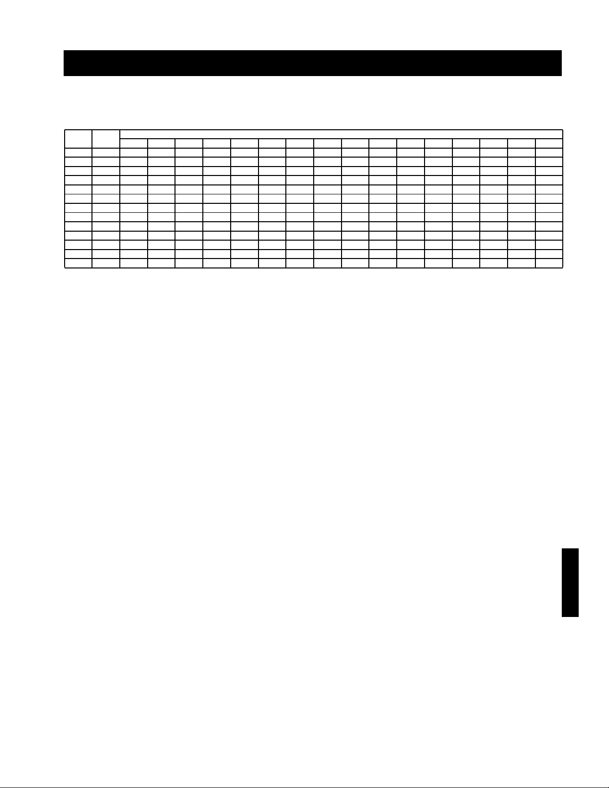
91
Reference
Reference - Performance Table
Input Output Temperature Rise (ºF)
(MBH) (MBH) 25 30 35 40 45 50 55 60 65 70 75 80 85 90 95 100
100 80 2963 2469 2116 1852 1646 1481 1347 1235 1140 1058 988 926 871 823 780 741
150 120 4444 3704 3175 2778 2469 2222 2020 1852 1709 1587 1481 1389 1307 1235 1170 1111
200 160 5926 4938 4233 3704 3292 2963 2694 2469 2279 2116 1975 1852 1743 1646 1559 1481
250 200 7407 6173 5291 4630 4115 3704 3367 3086 2849 2646 2469 2315 2179 2058 1949 1852
300 240 8889 7407 6349 5556 4938 4444 4040 3704 3419 3175 2963 2778 2614 2469 2339 2222
350 280 10370 8642 7407 6481 5761 5185 4714 4321 3989 3704 3457 3241 3050 2881 2729 2593
400 320 11852 9877 8466 7407 6584 5926 5387 4938 4558 4233 3951 3704 3486 3292 3119 2963
500 400 14815 12346 10582 9259 8230 7407 6734 6173 5698 5291 4938 4630 4357 4115 3899 3704
600 480
N
⁄A 14815 12698 11111 9877 8889 8081 7407 6838 6349 5926 5556 5229 4938 4678 4444
700 560
N
⁄A
N
⁄A 14815 12963 11523 10370 9428 8642 7977 7407 6914 6481 6100 5761 5458 5185
800 640
N
⁄A
N
⁄A
N
⁄A 14815 13169 11852 10774 9877 9117 8466 7901 7407 6972 6584 6238 5926
1,050 840
N
⁄A
N
⁄A
N
⁄A
N
⁄A
N
⁄A
N
⁄A 14141 12963 11966 11111 10370 9722 9150 8642 8187 7778
1,200 960
N
⁄A
N
⁄A
N
⁄A
N
⁄A
N
⁄A
N
⁄A
N
⁄A 14815 13675 12698 11852 11111 10458 9877 9357 8889
Performance Table
The following table gives the air volume in cubic feet per minute that is required to provide the desired
temperature rise for a given heating input. Model IG has a maximum 7,000 CFM capacity.
Page 92

IG/IGX IOM FS
Rev 2 May 2005
Copyright © 2005 Greenheck Fan Corp.
Warranty
Greenheck warrants this equipment to be free from defects in material and workmanship for a period of one year from
the purchase date. Any units or parts which prove defective during the warranty period will be replaced at our option
when returned to our factory, transportation prepaid.
Motors are warranted by the motor manufacturer for a period of one year. Should motors furnished by Greenheck
prove defective during this period, they should be returned to the nearest authorized motor service station. Greenheck
will not be responsible for any removal or installation costs.
As a result of our commitment to continuous improvement,
Greenheck reserves the right to change specifications without notice.
This manual is the property of the owner and is required for future maintenance.
Please leave it with the owner when you complete the job.
GREENHECK
P.O. BOX 410 SCHOFIELD, WISCONSIN 54476-0410
PH. 715-359-6171
www.greenheck.com
 Loading...