

Page 1
Indirect Gas-Fired
Technical Guide
May
2005
®
Page 2
2
TYPICAL
SPECIFICATIONS
H & V
CONTROLS
MUA
CONTROLS
FILTERS
DIFFUSERS
FURNACE
VENTING
MODEL IGX
DATA
MODEL IG
DATA
Table of Contents
Model Name Description. . . . . . . . . . . . . . . . . . . . . . . . . . . . . . . . . . . . . . . . . . . . . . . . . . . . . . . . . . . . . . . . . . 2
Technical Guide: Heat Exchange Material Design . . . . . . . . . . . . . . . . . . . . . . . . . . . . . . . . . . . . . . . . . . . . . . 3
Technical Guide: S-tube Furnace Design. . . . . . . . . . . . . . . . . . . . . . . . . . . . . . . . . . . . . . . . . . . . . . . . . . . . . 4
Model IG or IGX? . . . . . . . . . . . . . . . . . . . . . . . . . . . . . . . . . . . . . . . . . . . . . . . . . . . . . . . . . . . . . . . . . . . . . . . . 5
Model IG Performance Data . . . . . . . . . . . . . . . . . . . . . . . . . . . . . . . . . . . . . . . . . . . . . . . . . . . . . . . . . . . . . . . 6
Model IG Unit Dimensions and Weights . . . . . . . . . . . . . . . . . . . . . . . . . . . . . . . . . . . . . . . . . . . . . . . . . . . . . 7
Model IG Roof Curbs. . . . . . . . . . . . . . . . . . . . . . . . . . . . . . . . . . . . . . . . . . . . . . . . . . . . . . . . . . . . . . . . . . . . . 8
Model IG Evaporative Cooling . . . . . . . . . . . . . . . . . . . . . . . . . . . . . . . . . . . . . . . . . . . . . . . . . . . . . . . . . . . . . 9
Model IGX Performance Data & Motor Weights . . . . . . . . . . . . . . . . . . . . . . . . . . . . . . . . . . . . . . . . . . . . . . 10
Model IGX Unit Dimensions and Weights. . . . . . . . . . . . . . . . . . . . . . . . . . . . . . . . . . . . . . . . . . . . . . . . . 11-12
Model IGX Roof Curbs . . . . . . . . . . . . . . . . . . . . . . . . . . . . . . . . . . . . . . . . . . . . . . . . . . . . . . . . . . . . . . . . . . 13
Model IGX Evaporative Cooling . . . . . . . . . . . . . . . . . . . . . . . . . . . . . . . . . . . . . . . . . . . . . . . . . . . . . . . . . . . 14
Model IGX DX and Chilled Water Cooling Coil . . . . . . . . . . . . . . . . . . . . . . . . . . . . . . . . . . . . . . . . . . . . . . . 15
Furnace Venting Options . . . . . . . . . . . . . . . . . . . . . . . . . . . . . . . . . . . . . . . . . . . . . . . . . . . . . . . . . . . . . . 16-17
Weatherhood & Filter Options . . . . . . . . . . . . . . . . . . . . . . . . . . . . . . . . . . . . . . . . . . . . . . . . . . . . . . . . . . . . 18
Diffuser Options . . . . . . . . . . . . . . . . . . . . . . . . . . . . . . . . . . . . . . . . . . . . . . . . . . . . . . . . . . . . . . . . . . . . . . . . 19
Make-Up Air Furnace and Temperature Controls . . . . . . . . . . . . . . . . . . . . . . . . . . . . . . . . . . . . . . . . . . . . . 20
Technical Guide: Furnace Control and Turndown Ratio . . . . . . . . . . . . . . . . . . . . . . . . . . . . . . . . . . . . . . . . 21
Make-Up Air - Air Flow and Evaporative Cooling Controls. . . . . . . . . . . . . . . . . . . . . . . . . . . . . . . . . . . . . . 22
Industrial Make-Up Air Temperature Control Recommendation. . . . . . . . . . . . . . . . . . . . . . . . . . . . . . . . . . 23
TSCP Industrial Type Remote Control Panel . . . . . . . . . . . . . . . . . . . . . . . . . . . . . . . . . . . . . . . . . . . . . . . . . 24
Commercial Kitchen Make-Up Air Temperature Control Recommendation . . . . . . . . . . . . . . . . . . . . . . . . 25
Make-Up Air Controls . . . . . . . . . . . . . . . . . . . . . . . . . . . . . . . . . . . . . . . . . . . . . . . . . . . . . . . . . . . . . . . . . . . 26
Heating & Ventilating Controls. . . . . . . . . . . . . . . . . . . . . . . . . . . . . . . . . . . . . . . . . . . . . . . . . . . . . . . . . . 28-30
IG Typical Specification . . . . . . . . . . . . . . . . . . . . . . . . . . . . . . . . . . . . . . . . . . . . . . . . . . . . . . . . . . . . . . . . . . 32
IGX Typical Specification. . . . . . . . . . . . . . . . . . . . . . . . . . . . . . . . . . . . . . . . . . . . . . . . . . . . . . . . . . . . . . . . . 33
IG-HV Typical Specification. . . . . . . . . . . . . . . . . . . . . . . . . . . . . . . . . . . . . . . . . . . . . . . . . . . . . . . . . . . . . . . 34
IGX-HV Typical Specification . . . . . . . . . . . . . . . . . . . . . . . . . . . . . . . . . . . . . . . . . . . . . . . . . . . . . . . . . . . . . 35
Make-Up Air Product Selection Guide . . . . . . . . . . . . . . . . . . . . . . . . . . . . . . . . . . . . . . . . . . . . . . . . . . . . . . 36
Indirect Gas Furnace is ETL and cETL listed to ANSI Z83.8-2002
Indirect Gas Units are listed to UL1995.
Both are harmonized standards between USA and Canada
Model Name Description
IGX–115–H22
Model (X indicates
modular construction)
Blower Quantity
Blower Size
Housing Size
®
Page 3
3
Technical Guide: Heat Exchanger Material Selection
One important consideration when selecting an
indirect gas-fired furnace for a Make-Up Air or Heating
& Ventilating application is the heat exchanger
material. The conditions created inside of the heat
exchanger by the combustion process are the
greatest factor limiting the life of the furnace.
Selecting the proper heat exchanger material can
greatly reduce the effects of these conditions and
yield a long furnace life. To select the best heat
exchanger material, the application and climate
should be considered.
Corrosion and Thermal Expansion:
The first factor limiting the life of the heat exchanger
is the by-products of the combustion process. During
combustion process, water, nitrogen and sulfur form
inside of the heat exchanger, creating a highly
corrosive environment. The second factor is the high
temperature of the heat exchanger. Like any material,
a heat exchanger expands and contracts with
changes in temperature. The expansion and
contraction leads to high stresses in the heat
exchanger. The corrosive conditions, combined with
high stress can reduce furnace life if the wrong heat
exchanger material is selected.
Available Materials:
Greenheck offers two material options for heat
exchangers: aluminized steel and stainless steel. Both
are selected for the specific application of indirect gasfired heat exchangers, but have different strengths.
The first material option is aluminized steel; steel that
has been hot dipped in a molten aluminum bath. The
result is a triple layer of protection on the inside and
outside of the heat exchanger. The first protective
layer is an aluminum coating that is the first line of
defense against the corrosive conditions. Between the
aluminum and the steel is a second protective alloy
layer. As the outer aluminum corrodes, aluminum oxide
forms and provides a third layer of protection. In order
for the steel to begin corrosion, condensation must
penetrate the aluminum oxide, aluminum and the alloy.
Stainless steel is the second available material option.
Stainless gets its corrosive resistive properties from
its chromium content. As stainless is exposed to a
corrosive environment the chromium oxidizes and
forms a single protective layer over the steel that
slows corrosion.
Both materials are very effective at resisting corrosion,
but stainless holds up better to the extreme
temperatures found in some common applications. As
aluminized steel approaches 1100ºF the aluminum
begins scaling, exposing the steel. This temperature
corresponds to an air stream temperature rise of
approximately 70ºF. However, at temperatures below
the aluminized steel scaling point, the aluminized steel
tends to outperform stainless steel with respect to
heat stress
cracking.
From this
information,
Greenheck
recommends
aluminized
steel for
temperature
rises of 60ºF
or less and
stainless for
temperature rises greater than 60ºF.
Application and Climate Considerations:
Other than a corrosive environment, the air stream
temperature rise is the largest factor driving heat
exchanger material selection. With this in mind, we
will consider two distinct applications for indirect gasfired heaters: Heating & Ventilating and Make-Up Air.
From this, guidelines can be created to properly select
the heat exchanger material.
Most Heating
& Ventilating
applications
use a small
amount of
outside air (030%) which is
mixed with a
large amount of recirculated room air (70-100%). The
relatively warm mixed air typically requires a
temperature rise less than 50ºF, as illustrated in the
table to the right. As a result, aluminized steel heat
exchangers are recommended for H&V applications.
Make-up air applications are 100% outside air. As a
result, the required temperature rise of the heat
exchanger depends heavily on the climate. In mild
climates, with outdoor winter design temperatures
above 10ºF, a temperature rise of 60ºF or less is
typical and aluminized steel is recommended (based
upon a 70ºF discharge temperature). In colder
climates with outdoor winter design temperatures less
than 10ºF, the air stream
temperature rise often exceed
60ºF. When this occurs,
stainless steel is
recommended.
Summary:
For Heating & Ventilating applications and Make-Up
Air applications in mild climates, where the air stream
temperature rise is less than 60ºF, aluminized steel will
offer long furnace life and minimize the chance of heat
exchanger stress cracking. For Make-up Air
Applications in cold climates, where air stream
temperature rise exceeds 60ºF, stainless steel is
recommended.
Winter
Design
Temp.
Outside
Air
Percentage
Mixed
Air
Temp.
Required
Temp.
Rise*
Recommended
Heat Exchanger
Material
-20 15 57 34 Aluminized
-20 30 43 47 Aluminized
0 15 60 31 Aluminized
0 30 49 41 Aluminized
30 15 64 26 Aluminized
30 30 58 32 Aluminized
* Assumes 70ºF space temperature and 90ºF discharge temperature
Winter
Design
Temp.
Required
Temp.
Rise*
Recommended
Heat Exchanger
Material
-10 80 Stainless
0 70 Stainless
10 60 Aluminized
20 50 Aluminized
30 40 Aluminized
*Assumes a discharge temperature of 70ºF
®
Page 4
4
TYPICAL
SPECIFICATIONS
H & V
CONTROLS
MUA
CONTROLS
FILTERS
DIFFUSERS
FURNACE
VENTING
MODEL IGX
DATA
MODEL IG
DATA
The Problem
Many of today’s indirect gas-fired make-up furnace
specifications are based on yesterday’s technology
and often call for unneeded components that add
unneeded cost. Yesterday’s furnaces often featured a
clamshell style heat exchanger, which due to inherent
design problems resulted in condensation on the
burner and in the housing. To manage the
condensation and prevent corrosion, most clamshell
specifications call for stainless steel burners and drip
pans. Greenheck’s s-tube style furnace first limits
condensation, then manages any condensation that
does occur in a way that eliminates the need for
stainless steel burners and drip pans.
The largest inherent problem with a clamshell furnace
is the vertical heat exchanger configuration. The
burners fire vertically up into the heat exchanger. The
hot combustion gases travel up the straight single
pass heat exchangers and collect at the top where
they are vented. Because of the vertical configuration,
any condensation that develops in the heat exchanger
falls onto the burner and runs into the furnace
housing. The condensation contains by-products of
combustion, which are highly corrosive and destroy
the furnace. To protect the furnace section and
maintain an acceptable life, clamshell furnaces
include costly stainless steel burners and drip pans.
Many clamshell furnaces are gravity vented, which is
another problem that makes stainless steel burners
and drip pans necessary. Gravity venting means that
the combustion gases naturally vent through a stack,
like smoke in a fireplace naturally escapes through a
chimney. Gravity vented furnace efficiency is
dependent on the outside conditions. Wind blowing
over the stack can push the efficiency too high,
resulting in excessive condensation. Even more
condensation will develop when the furnace shuts
down. Any combustion gases remaining in the heat
exchanger will cool, condense and run down onto the
burner and into the housing.
Clamshell furnaces also present a significant design
limitation. The manifold, burners and drip pan are
located under the heat exchanger, preventing a
downblast discharge from the furnace section. If your
application calls for a downblast discharge, an
additional downturned section is required which
increases the unit footprint and cost.
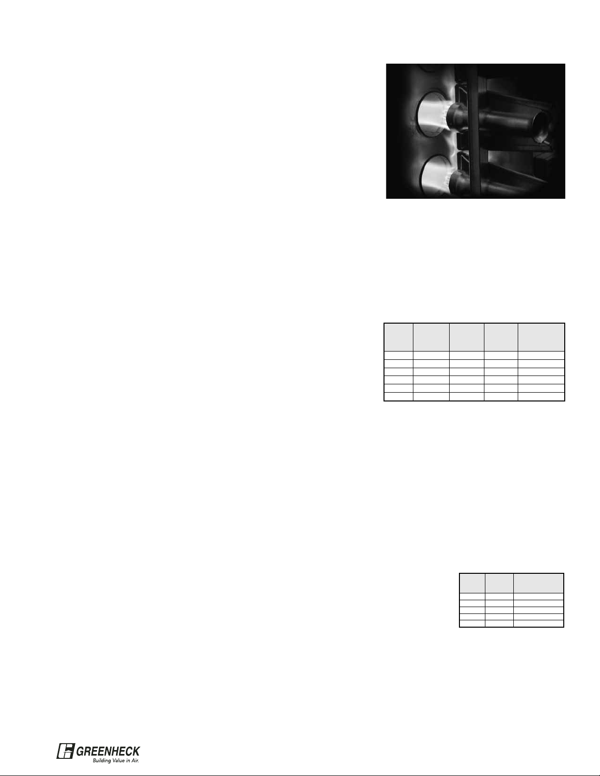
The S-tube Solution
Greenheck’s
furnace design
features
horizontally firing
burners and
power venting
with post purge
cycle which
together provide
flexibility,
maximum heat
exchanger life
and make
stainless steel
burners unnecessary and
drip pans obsolete.
Power venting maintains optimum combustion levels,
helping prevent the furnace efficiency from reaching
the level where condensation begins. The combustion
blower also enables a post purge cycle. When the
furnace shuts down, the combustion blower continues
to run, venting any combustion gases and drying the
heat exchanger. Unless removed, this combination of
gases and moisture would attack the inside of the
heat exchanger and promote corrosion.
Greenheck’s horizontally firing heat exchanger means
that the burners, manifold and gas train are located on
the side of the furnace, rather than below it. And
unlike a clamshell furnace, there is no drain pan under
the furnace. With the bottom of the furnace free and
clear, a downblast discharge is easily integrated into
the furnace section. Unlike a clamshell style furnace,
Greenheck furnace offers you the same compact
design, whether your application calls for a horizontal
or downblast discharge. The horizontally firing heat
exchanger also stops condensation from dripping
onto the burners and into the housing. Any
condensation will remain in the corrosion resistant
heat exchanger until it is power vented to the
outdoors.
Summary
When your application calls for indirect gas-fired
make-up air, be sure to specify the latest technology.
Horizontally firing burners and s-tube heat exchangers
with power venting and post purge cycle guarantee a
long furnace life in the most compact and flexible unit
configuration available.
Technical Guide: S-Tube Furnace Design
®
Page 5
5
• Stainless steel or aluminized heat exchanger
• 80% thermal efficiency
• Power vented furnace with post purge cycle
• Double wall furnace section
• G90 galvanized steel housing
• Factory wired control center
• Single point power connection
• Optional painted finish
• Optional separated combustion for indoor
installations
• Optional evaporative cooling
• Optional mixing box with controls
Model IG Model IGX
The Model IG has a less complex design and therefore typically offers the most economical solutions. The
information below identifies application parameters for the IG and IGX.
Model IG Model IGX
• Airflow up to 7,000 CFM • Airflow up to 23,000 CFM
• Heat up to 400 MBH • Heating up to 2,400 MBH
• Single speed fan • Two speed fan option
• Variable volume fan option
• DX and chilled water cooling options
• Occupied / Unoccupied control option (IGX-HV Only)
Model IG or IGX?
Greenheck offers two models of indirect gas-fired make-up air and heating units. Both IG and IGX models
include the following features and options:
®
Page 6
6
TYPICAL
SPECIFICATIONS
H & V
CONTROLS
MUA
CONTROLS
FILTERS
DIFFUSERS
FURNACE
VENTING
MODEL IGX
DATA
MODEL IG
DATA
Model Housing
MBH (input)
CFM RPM/BHP
Total Static Pressure in inches of WG
Min. Max 0.75 1.00 1.25 1.50 1.75
IG-108 H10 75 125
800
RPM 1109 1216 1311 1399 -
BHP 0.26 0.31 0.35 0.40 -
1,200
RPM 1347 1445 1530 - -
BHP 0.59 0.68 0.75 - -
IG-109
H10 75 175 1,400
RPM 998 1128 1245 1352 1456
BHP 0.41 0.48 0.57 0.67 0.78
H20 75 250 2,400
RPM 1216 1306 1397 1484 1569
BHP 1.10 1.31 1.40 1.60 1.70
IG-110
H10 150 175
2,000
RPM 912 1013 1110 1199 -
H20 200 300 BHP 0.59 0.71 0.80 1.0 -
H30 325 400 3,000
RPM 1097 1172 1244 1315 1386
BHP 1.4 1.6 1.7 1.9 2.1
IG-112
H20 175 300 2,600
RPM 761 853 934 1009 -
BHP 0.7 0.9 1.0 1.2 -
H30 175 400 4,400
RPM 939 1006 1073 1137 1197
BHP 2.1 2.4 2.6 2.9 3.1
IG-115
H20 250 300 4,000
RPM 681 756 822 892 -
BHP 1.3 1.5 1.8 2.1 -
H30 250 400 7,000
RPM 889 943 994 1044 1093
BHP 4.2 4.6 5.0 5.5 5.9
Air Performance Data & Furnace Availability
Note: The air performance data shown does not include internal static pressure losses due to items such as
filters, dampers and furnaces. For exact air performance data based on specific unit configuration, use the
Greenheck CAPS selection program.
Model IG Performance Data
IG Maximum Motor Size
IG Pressure Loss Table
Maximum Motor Size by Fan Size
Housing 108 109 110 112 115
H10
3
⁄4 11⁄2 3- -
H20 -3355
H30 --357
1
⁄2
Housing Size CFM Housing
Louvered
Weatherhood
Aluminum Mesh
V-Bank Filters
Inlet Damper Furnace
Evaporative
Cooler
H10
1200 0.12 0.02 < 0.01 < 0.01 0.23 0.03
2400 0.25 0.10 0.03 0.01 0.90 0.12
3000 0.26 0.16 0.04 0.02 1.41 0.19
H20
1500 0.10 0.03 < 0.01 < 0.01 0.12 0.05
3000 0.26 0.10 0.03 0.01 0.50 0.19
4400 0.34 0.23 0.06 0.03 1.07 0.20
H30
3000 0.16 0.10 0.03 0.01 0.23 0.19
5000 0.23 0.29 0.08 0.03 0.65 0.26
7000 0.45 0.57 0.15 0.07 1.28 0.50
Note: The 3, 5, and 71⁄2 HP motors are not available with
115V supply power. The 71⁄2 HP motor is only available
with 3 phase supply power.
®
Page 7
7
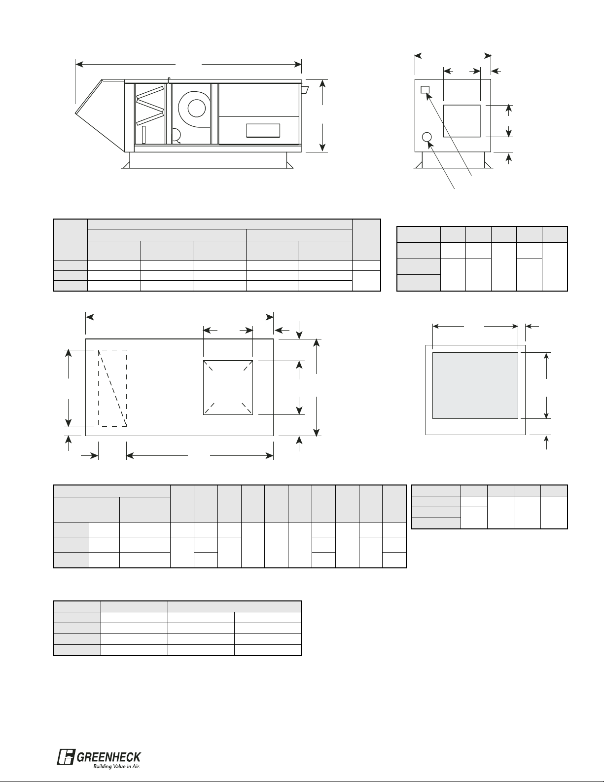
A
36 in.
Weatherhood
with Birdscreen
(Optional)
All IG housing sizes
are the same height.
Optional roof curb
G
JL
K
M
N
H
PR
T
S
Return Air
Opening
(Optional)
Downblast
Discharge
Opening
F
D
EC
B
Horizontal
Discharge
Power Vent Exhaust
Supply Gas Connection
*Unit weights by housing based on largest furnace and motor size available.
Total Unit with Evap Cooling
Housing Total Unit Weight Dry Weight Wet Weight
H10 380 695 936
H20 845 990 1231
H30 1190 1415 1797
Model IG Approximate Unit Weight (lbs.)
Model IG Return Air or Downblast Discharge Dimensions
Model IG Horizontal
Discharge Dimensions
Model IG Unit Base Unit Dimensions
Model IG Intake Dimensions
Housing V W X Y
H10 32.5
30.0 3.8 8.5H20
41.5
H30
Model IG Unit Dimensions
Filter Section Intake
All dimensions are shown in inches
All dimensions are shown in inches
Housing
A
Width
100% Outside Air Recirculation
Louvered
Weatherhood
Birdscreen
WeatherhoodNoWeatherhood
Louvered
WeatherhoodNoWeatherhood
H10 84.7 99.0 73.1 101.3 89.8 43.5
H20 87.6 102.0 76.2 104.3 92.8
52.6
H30 96.6 111.0 85.2 113.3 101.9
Housing B C D E F
H10 43.6 30.2
21.0
1.8
5.0
H20
52.6 39.2 1.0
H30
Housing G
H J K L M N P R S T
100%
Outside
Air
Recirculation
H10 73.1 89.0 43.5 26.5 23.7
2.7 3.9 12.4
73.8
12.9
35.6 2.1
H20 76.2 92.0
52.6
29.5
32.7
76.7
44.6
2.1
H30 85.2 101.0 38.5 85.7 2.1
Base of Unit
VY
W
X
®
Page 8
8
1.497
UNIT BASE PAN
0.500
1.652
1.500
WOOD NAILER
GPI CURB
SHEETMETAL SCREW
(BY OTHERS)
Sealant
Model IG Roof Curb Dimensions
Greenheck provides installation flexibility with multiple roof curb options that meet your needs. Whether for flat
or pitched roofs, insulated or non-insulated decks, Greenheck curbs facilitate installation and provide weather
tightness when roofed and flashed to
the factory supplied roof curb 2 inch
wood nailer. All curbs are
manufactured with 18 gauge
galvanized steel and may be shipped
with, or in advance of the equipment.
Roof curbs over 120 inches in length
(70 inches for GPIP at 24 inches
height) may ship knocked down for
ease of installation.
Roof Curb Model Options Table for Model IG
GPI GPNS GPS GPIP
Roof Deck
Flat x x x
Pitched x
Insulated x x
Non Insulated x x
Curb
Construction
Tabbed & Riveted x
Welded x x x
Curb Height in inches 12, 16, 20, 24 8, 12 8, 12 12, 16, 20, 24
Model IG
Roof Curb Unit Detail
Model IG Roof Curbs
Housing
A
B
100% Outside Air Recirculation
H10 57.5 89.0 40.0
H20 60.5 92.0
49.0
H30 72.5 101.0
Model IG Roof Curb Dimensions
Model IG Supply Side Roof Curb Dimensions
Housing C D E F G H J K
H10 26.44 23.67 30.5 35.5
2.72 2 3.85 12.48H20 29.44
32.67
33.75
44
H30 38.44 42
Housing L M N P Q R S T
H10
12.89
35.55
17
36.5
2.32 2 2.4 2H20 44.55
45.5
H30 44.55
Model IG Return Side Roof Curb Dimensions
*Recommended roof openings.
*Recommended roof openings.
Curb
Width
O.D.
E*
C
H
G
Curb Length O.D.
K
J
D
F*
2.25 in.
2.25 in.
Roof Opening
Supply
Duct
Curb
Width
O.D.
N*
L
R
Q
Curb Length O.D.
T
S
M
P*
1.75 in.
1.75 in.
Roof Opening
Return
Duct
B
Curb Width
O.D.
A
Curb Length O.D.
Return
Duct
Supply
Duct
TYPICAL
SPECIFICATIONS
H & V
CONTROLS
MUA
CONTROLS
FILTERS
DIFFUSERS
FURNACE
VENTING
MODEL IGX
DATA
MODEL IG
DATA
®
Page 9
9
Model IG Evaporative Cooler
Model IG Evaporative Cooling
Greenheck Evaporative Coolers
include a galvanized steel housing
with louvered intake, 2 in. aluminum
mesh pre-filters, stainless steel
evaporative media casing and drain
pan. Evaporative cooling media shall
be cellulose or fiberglass with a depth
of 12 inches for approximate cooling
effectiveness of 90%. Supply
connection is field located through
unit. Drain and overflow connections
shall be piped through the side for
easy installation. Equipment supports
for mounting are optional. See
Greenheck IOM for piping guidelines.
Model IG Total Unit Length with Evap
Drain
Connection
Overflow
Connection
Supply
Connection
FILTERS
Replacement
Media
Housing CFM 100% O.A.
Return Air
Unit
A B C D E F G Qty Size GFC P/N: Qty Size
H10 800 to 3,500 109.2 125.8 36.0 52.5 36.0 2.3 6.4 4.0 3.8 0.75 0.75 0.25 4 16x25x2 07451763
3 12x12x28.5
1 8x12x28.5
1 6x12x28.5
H20
800 to 3,500 112.2 128.8 36.0 52.5 36.0 2.3 6.4 4.0 3.8 0.75 0.75 0.25 4 16x25x2 07451763
3 12x12x28.5
1 8x12x28.5
1 6x12x28.5
3,501 to 7,000 112.2 128.8 36.0 68.6 36.0 2.3 6.4 4.0 3.8 0.75 0.75 0.25
2 16X25X2 07451763 5 12X12X28.5
4 16X20X2 07451437 1 6x12x28.5
H30
2,400 to 3,500 121.2 137.8 36.0 52.5 36.0 2.3 6.4 4.0 3.8 0.75 0.75 0.25 4 16x25x2 07451763
3 12x12x28.5
1 8x12x28.5
1 6x12x28.5
3,501 to 7,000 121.2 137.8 36.0 68.6 36.0 2.3 6.4 4.0 3.8 0.75 0.75 0.25
2 16X25X2 07451763 5 12X12X28.5
4 16X20X2 07451437 1 6x12x28.5
Typical Installation
Evaporative
Cooler
Equipment
Support
Curb
C
Louvered Intake
Pre-Filters
Stainless Steel
Drain Pan
Evaporative
Media
AB
Supply Connection
Field Located
Overflow
Drain
D
G
E
F
®
Page 10
10
TYPICAL
SPECIFICATIONS
H & V
CONTROLS
MUA
CONTROLS
FILTERS
DIFFUSERS
FURNACE
VENTING
MODEL IGX
DATA
MODEL IG
DATA
Hp1⁄41⁄23⁄4 111⁄2 2 21⁄2 3 5 71⁄2 10 15 20 25
Motor
Weight
16 20 22 36 42 45 67 69 75 110 115 203 268 350
Model IGX Motor Weights (lbs.)
Model Housing
MBH
CFM RPM/BHP
Total Static Pressure in inches of WG
Min. Max 0.75 1.00 1.25 1.50 1.75
IGX-108 H12 100 150
800
RPM 1109 1216 1311 1399 BHP 0.26 0.31 0.35 0.4 -
1,200
RPM 1347 1445 1530 - -
BHP 0.59 0.68 0.75 - -
IGX-109 H12 100 250
1,500
RPM 1014 1140 1255 1361 1460
BHP 0.45 0.54 0.63 0.73 0.84
2,400
RPM 1244 1329 1419 1503 1587
BHP 1.2 1.4 1.6 1.7 1.9
IGX-110 H12 100 250
2,000
RPM 0.995 1082 1166 1247 1325
BHP 0.93 1.1 1.2 1.4 1.5
3,000
RPM 1202 1275 1340 1401 1464
BHP 2.0 2.2 2.4 2.6 2.8
IGX-112 H22 150 600
2,600
RPM 761 853 934 1009 BHP 0.72 0.86 1.0 1.2 -
4,400
RPM 939 1006 1073 1137 1197
BHP 2.1 2.4 2.6 2.9 3.1
IGX-115 H22 150 600 4,000
RPM 741 808 871 931 986
BHP 2.0 2.3 2.6 2.9 3.2
IGX-118 H32 300 1,200
7,000
RPM 627 685 738 790 839
BHP 2.5 2.8 3.2 3.6 4.0
10,000
RPM 759 805 849 891 933
BHP 5.5 6.1 6.6 7.1 7.7
IGX-120 H32 300 1,200
10,000
RPM 590 634 678 723 765
BHP 4.0 4.5 5.0 5.6 6.1
15,000
RPM 763 795 829 861 892
BHP 10.9 11.6 12.3 13.1 13.8
IGX-122 H35 800 2,400
15,000
RPM 605 637 667 698 727
BHP 8.3 8.9 9.6 10.4 11.1
19,000
RPM 720 746 771 796 821
BHP 15.2 16.1 17.0 17.8 18.6
IGX-125 H35 800 2,400
19,000
RPM 563 594 625 655 683
BHP 9.8 10.7 11.7 12.8 13.8
23,000
RPM 643 671 697 723 748
BHP 15.9 16.9 18 19.2 20.4
Air Performance Data & Furnace Availability
Model IGX Pressure Loss Table
Note: The air performance data shown does not include internal static pressure losses due to items such as filters, dampers, cooling and furnaces. For exact air
performance data based on specific unit configuration, use the Greenheck CAPS selection program.
Model IGX Performance Data
Housing
Size
CFM Housing
Louvered
Weatherhood
Aluminum
Mesh V-Bank
Inlet
Damper
Furnace
Evaporative
Cooler
H12
1200 0.12 0.04 0.02 0.01 0.04 0.10
2500 0.27 0.15 0.07 0.05 0.05 0.43
3500 0.35 0.30 0.13 0.10 0.07 0.84
H22
3000 0.16 0.08 0.02 0.02 0.04 0.22
4000 0.28 0.15 0.04 0.04 0.04 0.40
6000 0.33 0.34 0.09 0.09 0.09 0.90
H32
7000 0.26 0.26 0.03 0.06 0.11 0.42
10000 0.27 0.53 0.06 0.11 0.23 0.86
14000 0.54 1.03 0.12 0.22 0.45 1.69
H35
15000 0.40 0.03* 0.09 0.11 0.84 0.35
19000 0.39 0.05* 0.14 0.17 1.35 0.57
23000 0.57 0.08* 0.21 0.25 1.98 0.83
*The louvered weatherhood is not
available on the IGX-H35.
Weatherhood loss is shown for
the birdscreen weatherhood.
®
Page 11
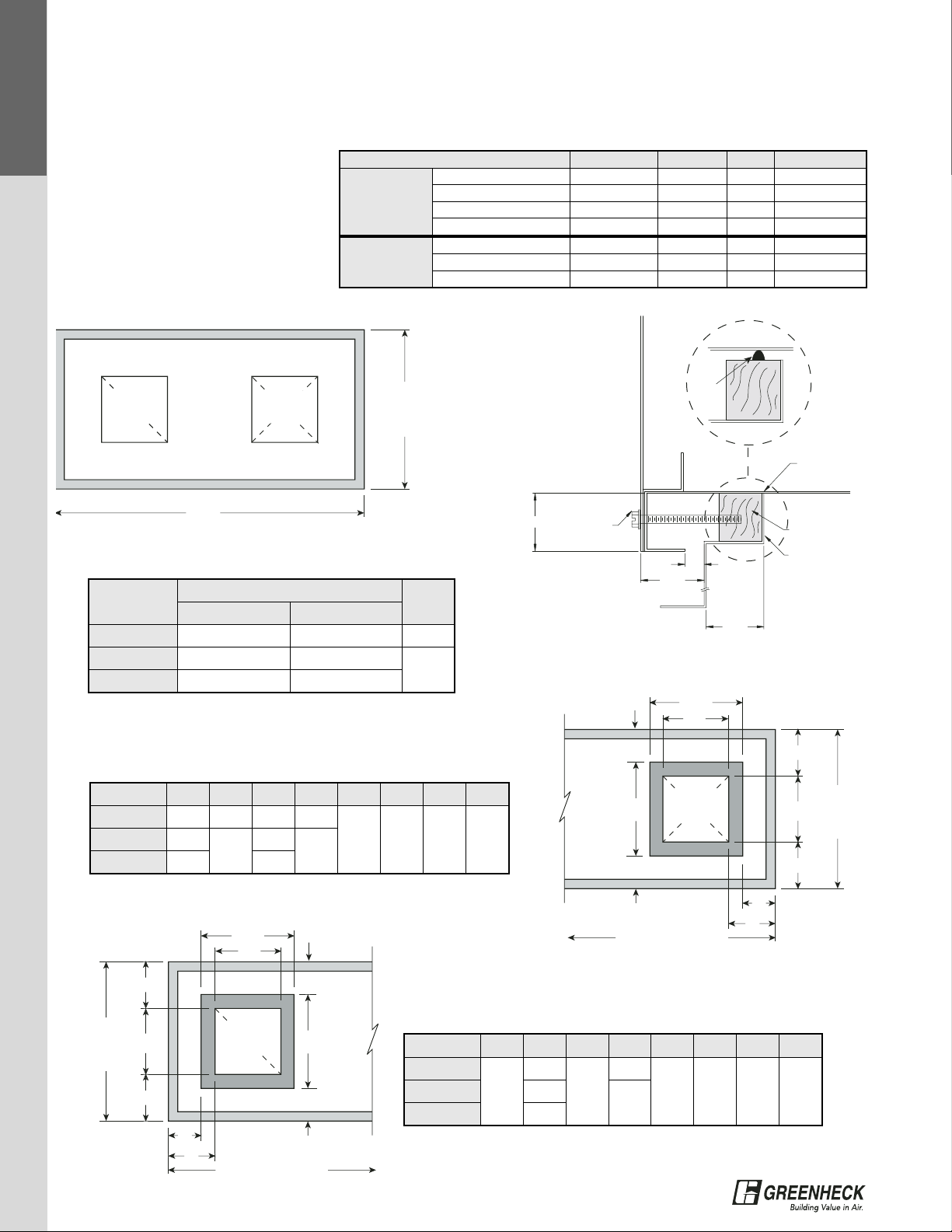
Model IGX Intake Dimensions
Model IGX Unit Dimensions
Intake
Width
Intake
Height
Housing TUVW
H12 30.9 34 4.9 1.1
H22 41.7 39.95 4.9 1.1
H32 49.75 43.75 4.9 1.2
H35 74 47 5.8 1.6
F
EDCBBBAAAA
AA
*AA - Filtered Weatherhood
Weatherhood Louvered V-Bank Mixing Box Cooling Fan Furnace Downturn
w/Birdscreen Intake w/Filters Filters Coil Plenum
Model IGX Unit Dimensions
*A downblast discharge on the IGX-H35 requires an additional downturned plenum section. All dimensions are shown in inches
Reference dimension S on page 12 for
total width of filter housing
11
Housing A AA AAA B BB
C
D Furnace Size E F
Downturn*
Plenum
Width
Low High
H12 24.8 31.5 13.8 21.5 30.7 30 50.4 42.5 100-250 33.2 39 n/a 44.1
H22 31.5 46.6 16.9 24 34 30 69.4 52.2
150-300
33.2
44.9 n/a
44.6
350-400 53.9
500-600 66.4 44.6
H32 47 48.5 16.9 25.8 40.7 98 66
350-400 33.2
48.7 n/a 53.1500-800 66.4
1050-1200 99.6
H35 47 n/a n/a 27.7 45.25 n/a 62
800 50
54.6 37 93.75
1200 74
1600 87.1
2000 111.1
2400 124.2
Housing Furnace Size G H J K L
H12
100
44.1
15
28.6
21.9
1.8
150 21 15.9
200 27 9.9
250 32 4.9
H22
150
53.4
21
28.6
21.8
1.8
200 27.1 15.8
250 31 11.9
300 38
4.9
350-400 53.4 38 28.7
500
53.4
31
28.6
11.9
600 38 4.9
H32
350
52.2
38
39.4
8.7
2
400 38 8.7
500-600 29 17.6 1.8
700-1200 29 8.7 2
H35 800-2400 93.75 35 75.75 18.6 3.4
IGX Horizontal Discharge Dimensions
HZ
Discharge
Opening
K
H
LJ
G
TW
Filter
U
Intake
V
®
Page 12

Model IGX Roof Curbs
Model IGX Unit Dimensions
Greenheck provides installation flexibility with multiple roof curb options that meet your needs. Whether for flat
or pitched roofs, insulated or non-insulated decks, Greenheck curbs facilitate installation and provide weather
tightness when roofed and flashed to
the factory supplied roof curb 2 inch
wood nailer. All curbs are
manufactured with 18 gauge
galvanized steel and may be shipped
with, or in advance of the equipment.
Roof curbs over 120 inches in length
(70 inches for GPIP at 24 inches
height) may ship knocked down for
ease of installation.
Roof Curb Model Options Table for Model IGX
GPI GPNS GPS GPIP
Roof Deck
Flat x x x
Pitched x
Insulated x x
Non Insulated x x
Curb
Construction
Tabbed & Riveted x
Welded x x x
Curb Height in inches 12, 16, 20, 24 8, 12 8, 12 12, 16, 20, 24
12
TYPICAL
SPECIFICATIONS
H & V
CONTROLS
MUA
CONTROLS
FILTERS
DIFFUSERS
FURNACE
VENTING
MODEL IGX
DATA
MODEL IG
DATA
Housing Weatherhood
V-bank
Filters
Mixing
Box
Cooling Coil Evap Cooler Fan Section Furnace
H12 48 83 180
Low
CFM
High
CFM
Wet Dry
Blower
Max hp
108
3/4
109
3 hp
110
3 hp
MBH 100 150 200 250
284 327 355 197
Weight
260 316 329
Weight
295 305 313 367
H22 68 137 256
Low
CFM
High
CFM
Low
CFM
High
CFM
Low
CFM
High
CFM
Blower
Max hp
112
3 hp
115
71/2 hp
MBH 150 200 250 300 350 400 500 600
488 550 489 546 248
280
Weight
474 560
Weight
304 313 367 382 425 425 734 764
H32 159 185
303 549
Low
CFM
High
CFM
Low
CFM
High
CFM
Blower
Max hp
118
10 hp
120
15 hp
MBH 350 400 500 600 700 800 1050 1200
640 750 305
330
Weight
803 888
Weight
425 425 734 764 850 850 1275 1275
H35 176 270 620 N/A 1885 970
Blower
Max hp
122
20 hp
125
25 hp
MBH 800 1200 1600 2000 2400
Downblast
Plenum
Weight
1303 1343
Weight
1488 2176 2681 3369 3874 673
Model IGX Approximate Unit Weight
*Reference Cooling Section on page 14 and 15 to determine high or low cfm cooling coil for H12 to H22 units and evaporative cooler H22 to H32. *Fan
section weight includes maximum motor hp weight. All weights shown in pounds (lbs.)
MODEL IGX
DATA
L
Downblast Discharge
Opening
Mixing Box
Top View
Airflow
Airflow
Housing N P Q R S
H12 20 21 4.7 6.1 33.2
H22 22 32 8.7 6.1 44.1
H32 28.3 41.3 9.2 5.5 52.2
H35 31.25 55.5 8.25 10.9 77.3
IGX Mixing Box Dimensions
Housing Furnace Size HH JJ KK LL
H12 100-250 25 23 3.9 5.2
H22
150-300
26
25
3.9 5.2350-400 34
500-600 25
H32 350-1200 26 34 3.5 5.3
H35 800-2400 28.5 66.5 4.4 21.8
IGX Downblast Discharge Dimensions
NQ
Return
Air
R
S
P
Opening
HH KK
Downblast
Discharge
Opening
L
JJ
®
Page 13

13
Model IGX Roof Curb Dimensions
*Recommended roof openings.
*Recommended roof openings.
Housing
Size
N P Q R S T U V W X
H12 20 21 201⁄4 25 17⁄8 41⁄4 41⁄4 13⁄4 21⁄4 21⁄4
H22 22 32 223⁄8 36 17⁄8 41⁄4 41⁄4 13⁄4 21⁄4 21⁄4
H32 281⁄4 411⁄4 281⁄2 44 17⁄8 35⁄8 35⁄8 13⁄4 21⁄4 21⁄4
H35 311⁄4 551⁄2 33 601⁄2 4993
1
⁄4 61⁄2 61⁄2
Housing
Size
C D E F G H J K L M
H12 25 23 26 25 21⁄2 31⁄4 31⁄4 22
1
⁄4 21⁄4
H22
(150-300, 500-600)
26 25 27 36 21⁄2 3121⁄2 22
1
⁄4 21⁄4
H22
(350, 400)
26 34 27 36 21⁄2 31⁄4 31⁄4 22
1
⁄4 21⁄4
H32 26 34 27 44 21⁄2 31⁄2 11 2 21⁄4 21⁄4
H35 281⁄8 661⁄2 295⁄8 68 23⁄4 31⁄4 33⁄4 22
1
⁄2 3
B
Curb Width
O.D.
A
Curb Length O.D.
Return
Duct
Supply
Duct
Curb
Width
O.D.
E*
C
K
G
Curb Length O.D.
J
H
D
F*
L
M
Roof Opening
Supply
Duct
Curb
Width
O.D.
Q*
N
V
S
Curb Length O.D.
U
T
P
R*
W
X
Roof Opening
Return
Duct
IGX-H35
IGX-H12, H22, H32
Roof Curb Unit Detail
Housing
A
BFurnace Size
Mixing
Box
Downturned
Plenum
DX or CW Coil
<=400 500-600 700 800 1050 1200 1600 2000 2400 Short Long
H12 72.75 --------+30.75 - +30 +50.5 29.5
H22 82.5 115.75 -------+34 - +30+69.5 40.5
H32 96.25 129.25 129.25 129.25 162.5 162.5 - - - +40.5 - - +98 48.5
H35 - - - 108.75 - 132.75 145.75 169.75 182.75 +45.25 +37 - - 73.5
SHEETMETAL
4.00
SCREW
(BY OTHERS)
Main Rail
Sealant
1.00
WOOD NAILER
GPI CURB
0.500
1.75
1.50
SHEETMETAL
SCREW
(BY OTHERS)
Main Rail
WOOD NAILER
GPI CURB
0.500
1.75
1.50
®
Page 14

14
TYPICAL
SPECIFICATIONS
H & V
CONTROLS
MUA
CONTROLS
FILTERS
DIFFUSERS
FURNACE
VENTING
MODEL IGX
DATA
MODEL IG
DATA
MODEL IGX
DATA
Model IGX Evaporative Cooling
Greenheck Evaporative Coolers
include a galvanized steel housing
with louvered intake, 2 in. aluminum
mesh pre-filters, stainless steel
evaporative media casing and drain
pan. Evaporative cooling media shall
be cellulose or fiberglass with a
depth of 12 inches for approximate
cooling effectiveness of 90%. The
evaporative cooler is designed for a
maximum airflow velocity of 600 fpm.
Supply connection is field located
through unit. Drain and overflow
connections shall be piped through
the side for easy installation.
Equipment supports for mounting are
optional. See Greenheck IOM for
piping guidelines.
Dimensional Data
Drain
Connection
Overflow
Connection
Supply
Connection
FILTERS Replacement Media
HOUSING CFM A B C D E F G Qty Size GFC P/N: Qty Size
H12 800 to 3,000 30.2 33.2 40.0 5.75 1.4 7.4 1.4 0.75 0.75 0.25 4 16x16x2 07460640
2 12x12x27.5
1 6X12x27.5
H22
2,000 to 4,800 30.2 44.0 46.0 5.75 3.1 7.4 3.1 0.75 0.75 0.25
2 16x20x2 07451437 3 12x12x33
2 20x20x2 07451438 1 7.5x12x33
4,801 to 7,000 34.7 51.5 46.0 5.75 6.8 7.7 6.8 0.75 0.75 0.25
3 12x20x2 07451766
5 12x12x33
3 20x25x2 07451439
H32
4,500 to 9,000 34.7 66.5 48.7 5.75 6.8 7.7 6.8 0.75 0.75 0.38
6 16x20x2 07451437 5 12x12x35.75
2 20x20x2 07451438 1 6x12x35.75
9,001 to 14,000 38.1 96.5 48.7 2.75 11.6 4.7 11.6 0.75 0.75 0.38
6 16x25x2 07451763
8 12x12x39
3 12x25x2 07451767
2 16x20x2 07451437
1 12x20x2 07451766
H35 10,000 to 23,000 38.1 120.5 55.7 2.84 11 4.6 11 0.75 0.75 0.38
8 23x21x2 07454956
10 12x12x45
4 23x19x2 07454951
Model IGX Evaporative Cooler
All dimensions are shown in inches
Evaporative
Cooler
Equipment
Support
Curb
Typical Installation
Pre-Filters
Louvered Intake
Stainless Steel
Drain Pan
Evaporative
Media
AB
D
G
E
Supply Connection
Field Located
Overflow
Drain
C
F
®
Page 15
15
Housing CFM
Coil Dimensions
(HxL)
A B
Housing
Height
H12
Low 1,250 to 2,150 27x22 30 33 39
High 2,151 to 3,400 27x34 50 33 39
H22
Low 2,300 to 3,800 33x33 30 44 45
High 3,801 to 6,700 33x56 69 44 45
H32
High
5,350 to 11,000 36x85 98 52 48.7
IGX Cooling Coil
Top View
A
B
Top View
A
B
Low CFM High CFM
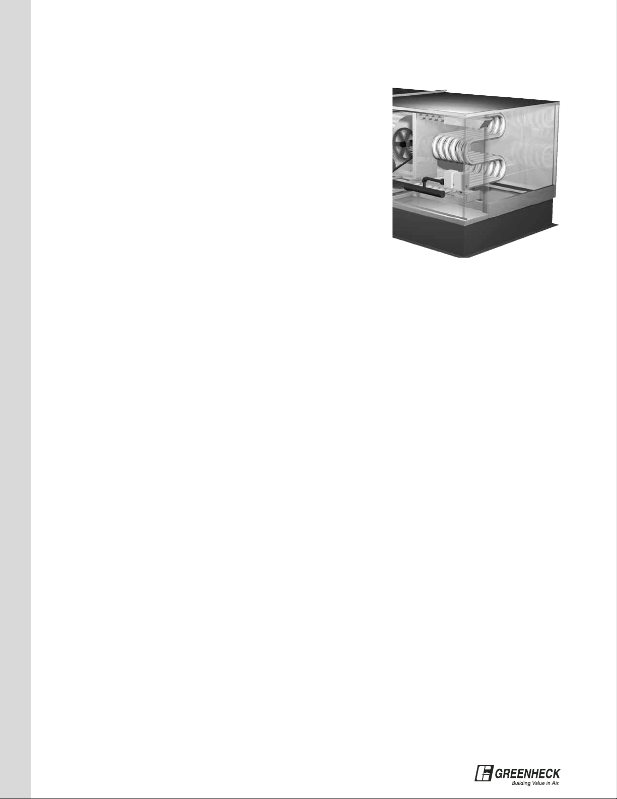
Model IGX DX and Chilled Water Cooling Coil
• Insulated double wall construction
• Double sloped stainless steel drain pan
• Coil and drain connections are stubbed thru side panel
for easy hook up
• DX liquid line connections ship internal to unit with
access door ensuring damage free delivery
• Cooling controls, thermal expansion valves, condensers
and compressors are by others
• Maximum airflow velocity of 525 fpm
All dimensions are shown in inches
®
Page 16
16
TYPICAL
SPECIFICATIONS
H & V
CONTROLS
MUA
CONTROLS
FILTERS
DIFFUSERS
FURNACE
VENTING
MODEL IGX
DATA
MODEL IG
DATA
FURNACE
VENTING
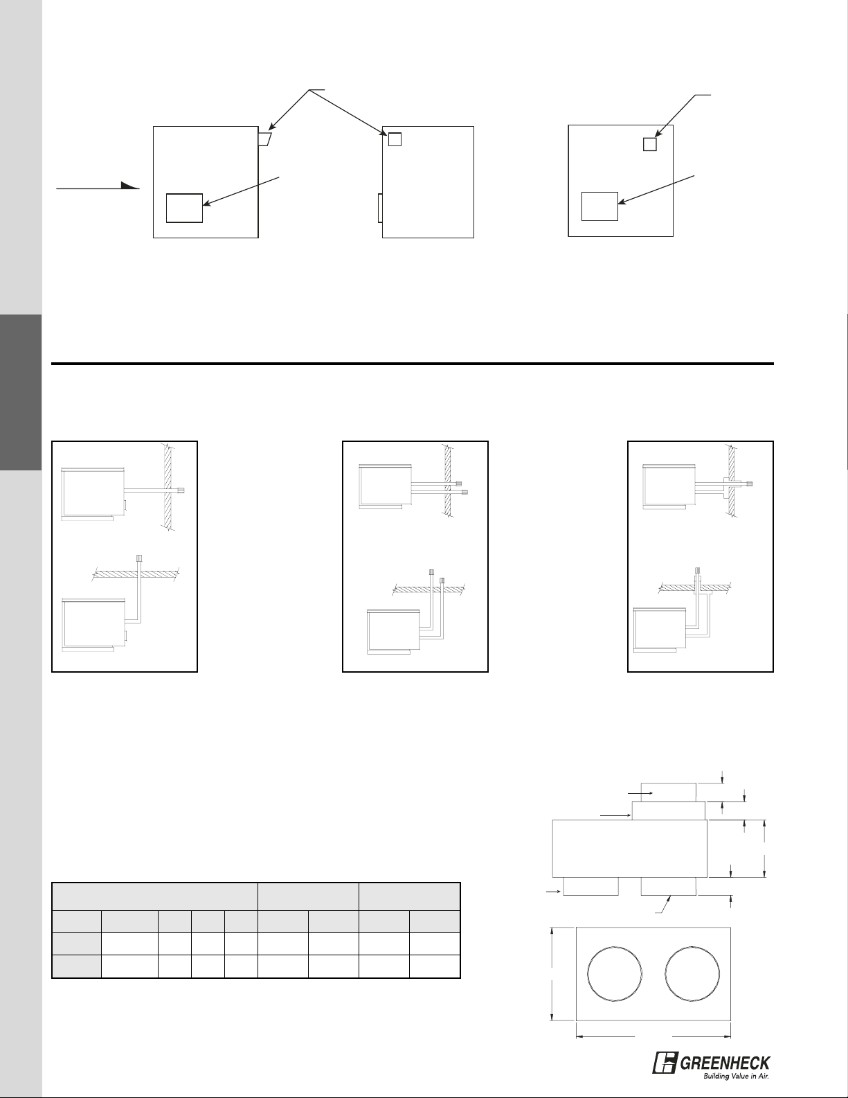
Indoor Venting Options
When your application calls for indoor installation, Greenheck offers multiple venting options:
Basic Indoor Venting
Separate 2-Pipe Venting
Concentric Venting
Through WallThrough Wall
Through Wall
Through Roof
Through Roof Through Roof
Concentric venting uses
outdoor air for combustion and
vents combustion by-products
outdoors through a vent line,
but offers you the benefit of
only one roof or wall
penetration.
Separate 2-pipe venting uses
outdoor combustion air and
vents combustion by-products
outdoors through a vent line,
requiring separate roof or wall
openings for each line
.
Basic indoor venting uses
indoor air for combustion and
vents combustion by-products
outdoors through a vent line in
the wall or roof.
Furnace Outdoor Venting
Model IG Model IGX
The Greenheck outdoor vent options include a combustion air intake vent and power exhaust vent. An optional
combustion exhaust vent terminal is available for installation on a field supplied vertical stack. Check local
codes for venting requirements.
Combustion exhaust discharge must be located a minimum of 42 in. from any combustion material. Maintain a
minimum of 4 feet clearance from electrical meters, gas meters, regulators, and relief equipment – Use minimum
6 feet clearance in Canada.
2
2
C
2
B
A
Exhaust Connection
continues through box
Non-concentric side
Combustion Air Connection
Concentric Side
Exhaust Connection
Concentric Side
Combustion Air Connection
Non-concentric side
Non-Concentric Side
Vent Diameter (inches)
Concentric Side
Vent Diameter (inches)
Model
Furnace Size
(MBH)
A B C Exhaust
Combustion
Air
Exhaust
Combustion
Air
CVA-475 to 175111164446
CVA-6 200 to 400 17 10.25 6.25 6668
Concentric Vent Adapter Dimensions
Concentric Vent Adapter
The concentric vent adapter allows for only one roof penetration for both
combustion air intake and exhaust. Vent terminals are included. Exhaust
pipe is by others and must be approved for Category III appliance or
single wall, 26 gauge or heavier galvanized pipe vent.
All dimensions are shown in inches
Note: The IGX-H35 is outdoor installation only and the indoor venting
options do not apply.
Combustion
Air Exhaust
Airflow
Side View Discharge End
Combustion
Air Intake Vent
Side View
Combustion
Air Exhaust
Combustion
Air Intake Vent
®
Page 17
17
Model IGX (H12, 22, 32)
Model IG
IG Reference - Venting Connection Location (H10, 20, 30)
Model IGX - Venting Connection Location (H12, 22, 32)
IG
Housing
A B C D E F
Flue Connection Size (Diameter)
Standard Non-Concentric Concentric
Exhaust Exhaust Intake Exhaust Intake
10 3.89 5.12 9.12 11.59 23.11 27.58 4.0 4.0 4.0 4.0 6.0
20 3.91 3.89 7.89 11.62 25.34 32.27 6.0 6.0 6.0 6.0 8.0
30 3.91 3.89 7.89 11.62 25.34 32.27 6.0 6.0 6.0 6.0 8.0
Housing MBH C D
H12 100-250 8.5 8.0
H22 150-600 8.5 8.0
H32 350-1200 8.5 8.0
IGX Gas Connection (H12, 22, 32)
All dimensions are shown in inches
All dimensions are in inches. Dimensions B and E are not needed for standard venting.
A round adapter should be used for the exhaust connection.
Housing
Furnace
Size
A B E F
Flue Connection Size (Diameter)
Standard Non-Concentric Concentric
Exhaust Exhaust Intake Exhaust Intake
H12
100-150 4.45 8.45 23.43 27.9 4 4 4 4 6
200-250 5.64 9.64 23.97 30.9 6 6 6 6 8
H22
150 4.45 8.45 29.38 33.85 4 4 4 4 6
200-300
5.67 9.67
24.97 31.9
66668350-400 19.01 25.94
500-600 24.97 31.9
H32 350-1200 5.96 9.71 28.31 35.24 6 6 6 6 8
Model IGX - Venting and Gas
Connection Location (H35)
32.660
14.098
49.89
6.771 ± 1
28.109
18.514 ± 2
1 in. NPT gas connection
Only used with 800mbh
furnace
4x4 Exhaust Outlet
Combustion air intake
Exhaust Outlet
Combustion Air Inlet
F
E
D
A
B
C
3/4 In. Gas Connection
3/4" Gas Connection
C
Exhaust Air Outlet
Combustion Air Intake
F
E
D
A
B
®
Page 18
18
TYPICAL
SPECIFICATIONS
H & V
CONTROLS
MUA
CONTROLS
FILTERS
DIFFUSERS
FURNACE
VENTING
MODEL IGX
DATA
MODEL IG
DATA
FILTER
DIFFUSERS
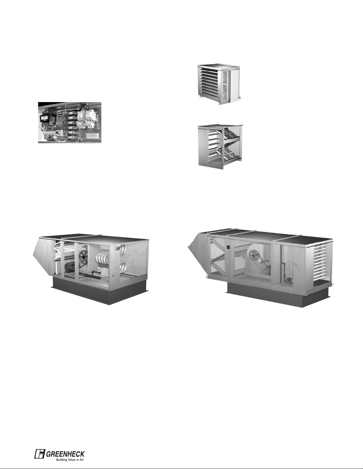
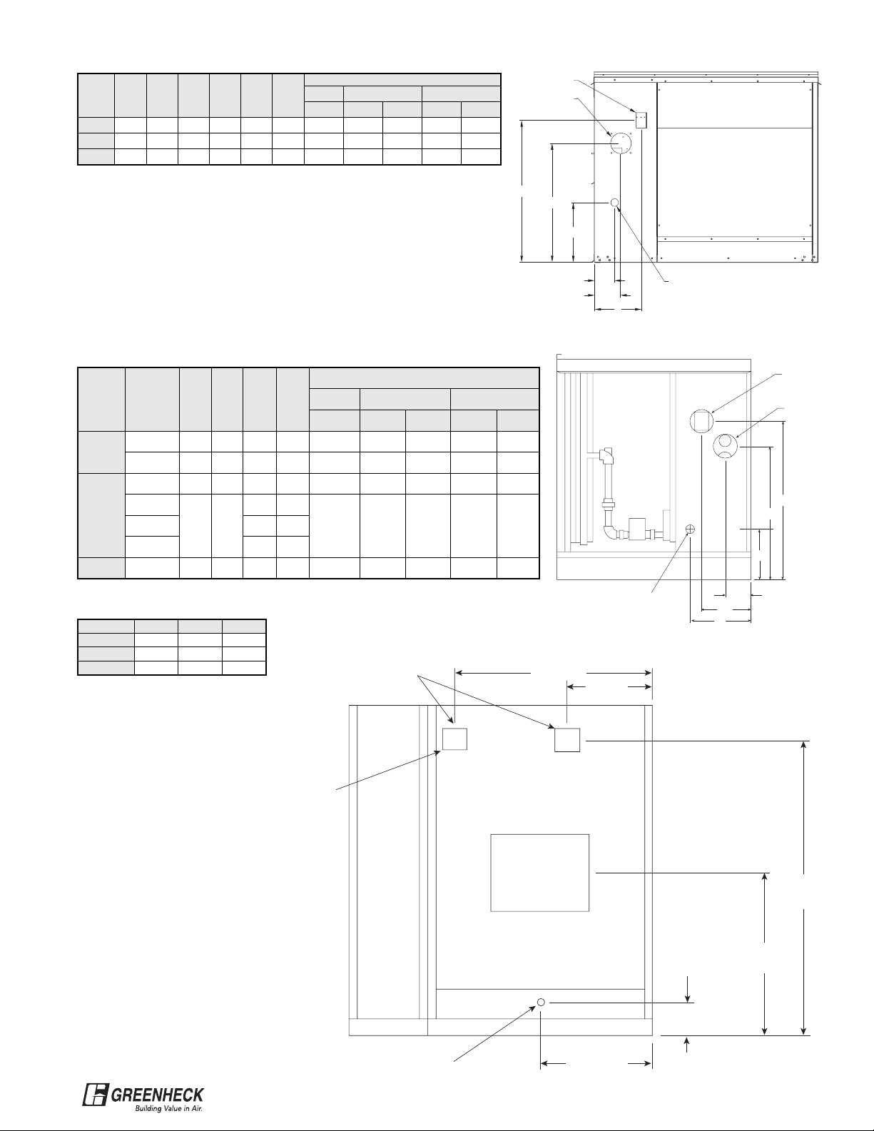
Greenheck weatherhoods include 18 gage galvanized construction with integral galvanized wire mesh inlet
screen for outdoor mounting. Filtered weatherhoods feature 2 inch aluminum mesh filters with a slide out
design for easy service access for
service. Louvered intakes include
moisture-eliminating louvers with 2
inch aluminum mesh filters that
provide a compact space saving
design. All three intake options are
designed to prevent water and debris
from entering the system.
V-Bank Filters
Weatherhood w/Birdscreen
Louvered Intake
Housing Filter Type (2 in.) Qty Nominal GFC P/N Qty Nominal GFC P/N
H10
Aluminum Mesh 8 12x20x2 00451766 4 16x20x2 00451437
Disposable 8 12x20x2 00463685 - - -
H20
Aluminum Mesh 8 12x25x2 00451767 4 16x25x2 00451763
Disposable 8 12x25x2 07456452 - -
H30
Aluminum Mesh 8 12x25x2 00451767 4 16x25x2 00452915
Disposable 8 12x25x2 00456452 - - -
Model IG
V-Bank Filters
Weatherhood w/Birdscreen
Louvered Intake Filtered Weatherhood
Housing Filter Type (2 in.) Qty Nominal GFC P/N Qty Nominal GFC P/N Qty Nominal GFC P/N
H12
Aluminum Mesh 4 15x20x2 00458206 4 16x16x2 00460640 4 16x20x2 00451437
Disposable 4 15x20x2 00458208 - - - - - -
H22
Aluminum Mesh 6 20x20x2 00451438 4 20x20x2 00452916
2 20x25x2 00453499
4 12x25x2 00451767
Disposable 6 20x20x2 00451435 - - - - - -
H32
Aluminum Mesh 10 20x25x2 00451439 6 16x25x2 00452915 6 20x25x2 00453499
Disposable 10 20x25x2 00451436 - - - - - -
H35
Aluminum Mesh 15 20x25x2 00451439 - - - - - -
Disposable 15 20x25x2 00451436 - - - - - -
Model IGX
*V-bank filters apply to units with Mixing Box or Standard Weatherhood with Birdscreen. All dimensions shown in inches.
Filters
Weatherhood Options
Weatherhood with Birdscreen
IG & IGX
Louvered Intake
IG & IGX
Filtered Weatherhood
IGX
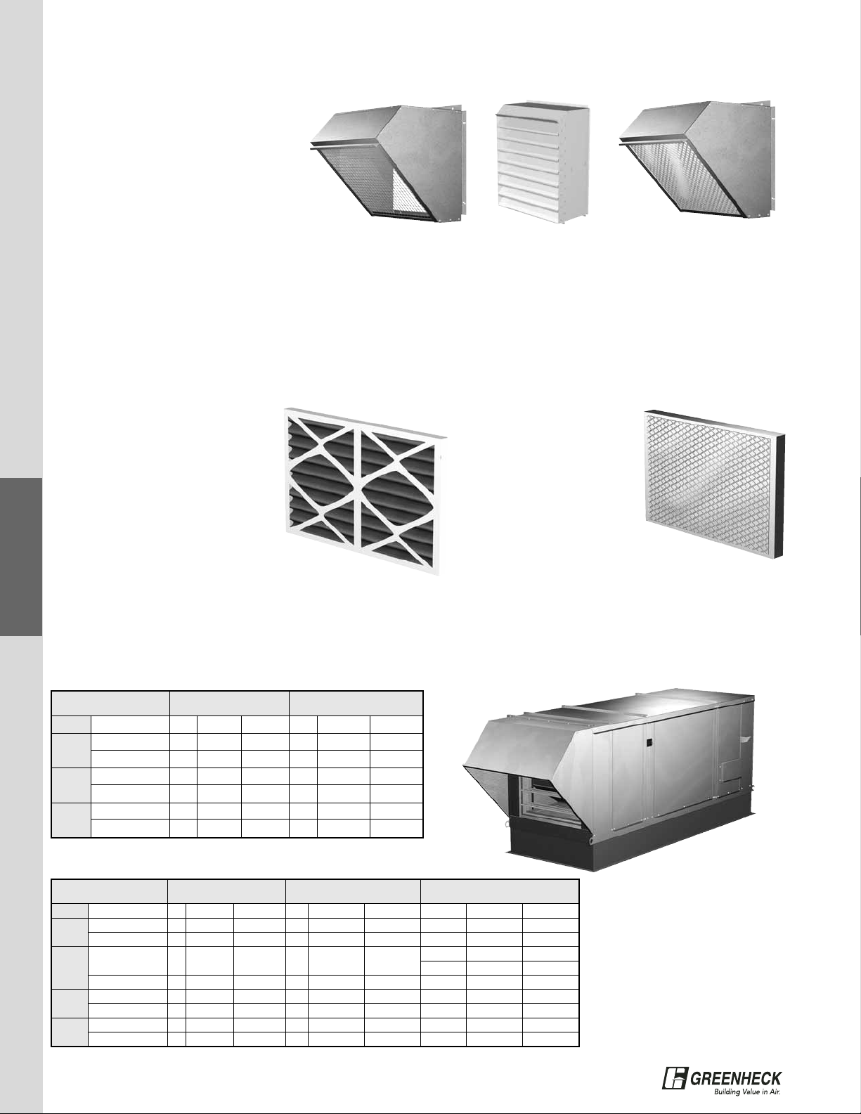
Greenheck offers 2 inch aluminum mesh or pleated disposable filters. Aluminum mesh filters are approximately
5% efficient and are typically applied to most industrial, manufacturing, and kitchen applications. Disposable
filters are 30% efficient, include a MERV 7 rating and are applied where a higher degree of cleanliness is
required such as schools, nursing homes, packaging, and food processing plants. Please consult the
Greenheck factory for high efficiency filtration (up to 95%).
Disposable Filters
• Die cut double wall moisture
resistant beverage board frame
• Adhesive bond of frame and
media prevent bypass
• High loft blended synthetic and
natural fiber media with fire
retardant additive
• Galvanized steel support grid
• Face velocity rating of 300 to 625 fpm
• 30% Average efficiency (ASHRAE 52-76)
• MERV 7 rating (ASHRAE 52.2)
• arrestment value exceeds 90%
• UL Class 2 Rated per UL Standard 900
Aluminum Mesh Filters
• Bonded aluminum
media provides
strength and durability
• Aluminum media in
varying pattern
obtains maximum
depth loading
• Easily washable
• Delivers high performance at varying
velocities up to 650 fpm
• Average arrestment of 68% @ 520 fpm when
tested per ASHRAE 52-76
• Meets UL Class 2 requirements
®
Page 19

19
4-Way Diffuser
Blower
Size
Maximum
CFM
A B C D E F G
IG/IGX 112-115 8,000 41.75 41.75 8.75 32 6 22 18
IGX 118-120 16,000 49.75 49.75 12.75 42.0 10.0 28.00 26.00
1-Way Diffuser
2,000 - 4,000 cfm
IGX-H12 and H22 Only
Note: Diffuser may require duct
transition from discharge of unit.
2-Way Diffuser
4,000 - 6,000 cfm
IGX-H12 and H22 Only
Note: Diffuser may require duct
transition from discharge of unit.
Diffuser Options
27.791
1.000
TYP. 4 SIDES
7.630
FLANGE
17.000
6.096
15.558
24.192
14.656
12.300
37.630
FLANGE
1.000
TYP. 4 SIDES
5.929
17.283
21.694
TYP.
31.744
16.625
A
20.348
17.308
16.406
B
F
G
E
D
®
C
Page 20
20
TYPICAL
SPECIFICATIONS
H & V
CONTROLS
MUA
CONTROLS
FILTERS
DIFFUSERS
FURNACE
VENTING
MODEL IGX
DATA
MODEL IG
DATA
MUA
CONTROLS
Make-Up Air Furnace & Temperature Controls
Capable of operating on Natural Gas or LP vapor, the Greenheck furnace includes power venting, main gas
pressure regulator, main gas valve, direct spark ignition system, high limit, 24 V control transformer. Furnace
turndown capability is maximized with your choice of electronic staged, electronic modulation, or external
supplied 0-10 VDC or 4-20 mA furnace control.
Electronic Modulation
• Maxitrol 92 Series
– Single furnace control
– Up to 400 MBH
– 55 to 90 discharge
temperature range
– Up to 2:1 modulating
turndown per furnace
• 4:1 Modulating Turndown
– Single, double, or triple furnace control
– Up to 1200 MBH
– 55 to 95 discharge temperature range
– Up to 4:1 modulating turndown per furnace
– 8:1 turndown on double furnace, 12:1 turndown
on triple furnace
Stage Control
• Johnson A350 Series
– Single, double or triple
furnace control
– Up to 1200 MBH
– 55 to 90 discharge
temperature range
– Up to 2:1 staged turndown
per furnace
• 8:1 Staged Turndown
– Single, double, or triple furnace control
– Up to 1200 MBH
– 55 to 95 discharge temperature range
– Up to 8:1 modulating turndown per furnace
– 16:1 turndown on double furnace, 24:1
turndown on triple furnace
Housing
Modulation Control Staged Control
Maxitrol 92 Johnson FX Controller Johnson A350 Johnson FX Controller
H10
2:1 4:1 2:1 8:1
H20
H30
IG Turndown Ratio Availability
Housing Furnace Size
Modulation Control Staged Control
Maxitrol 92 Johnson FX Controller Johnson A350 Johnson FX Controller
H12 100 - 250 2:1 4:1 2:1 8:1
H22
150 - 400 2:1 4:1 2:1 8:1
500 - 600 n/a 8:1 4:1 16:1
H32
350 - 400 2:1 4:1 2:1 8:1
500 - 800 n/a 8:1 4:1 16:1
1050 - 1200 n/a 12:1 6:1 24:1
H35
800
n/a n/a n/a
4:1
1200 6:1
1600 8:1
2000 10:1
2400 12:1
IGX Turndown Ratio Availability
Room Override
• Space mounted stat increases discharge
air temperature by up to 40º F when
space temperature is below its set point.
Once satisfied, the unit discharge temp
reverts back to the setpoint on the
discharge temperature selector.
• Coiled bimetal element
• Single stage SPST mercury switch
• Setting lever and thermometer scale on thermostat
face
• Standard off-white color
• Straight in wiring capability
• Mount directly on wall or vertical panel box
• Dimensions: 43⁄4 in. high, 27⁄8 in wide, 13⁄8 in. deep
• CSA certified File No. LR95329-1
External Signal Furnace Control
• Receives external (4-20mA or 0-10 VDC by others)
to modulate furnace.
®
Page 21
21
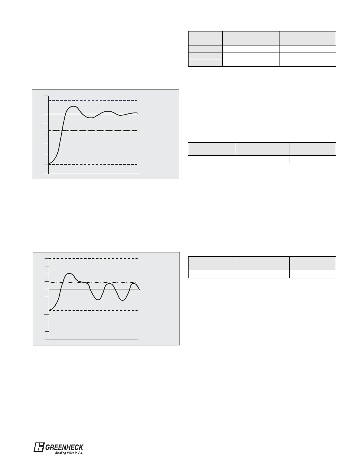
Electronic Modulation
The benefit of electronic modulation is that it enables
precise LAT (leaving air temperature) control. As
outdoor air temperatures vary, the furnace can
modulate the gas flow and deliver a constant LAT. The
graph below illustrates how this system would react to
a start up condition at 20º F.
Operation within electronic modulation range; LAT
control of ± 2º F
However, a potential problem exists if the modulation
range has a limited turndown. Many manufacturers of
indirect gas-fired MUA units only offer electronic
modulation with a 2:1 turndown. This can result in the
performance illustrated by the graph below with the
same system operating at on outdoor temperature of
45º F.
Operation not within electronic modulation range;
LAT control of + 10º F
The key point is that a MUA unit with electronic
modulation only gives you precise temperature control
when the furnace operates within its modulation
range. Outside of the modulation range, the furnace
will behave like a single-stage unit and deliver
inconsistent LAT.
How often the MUA unit actually runs in its modulation
range is dependent on the turndown ratio. Based on
weather bin data analysis for a wide range of climates,
the table above provides reasonable estimates.
The solution to this potential problem is specifying a
higher turndown ratio so that operation in the
modulation range is maximized. Greenheck offers the
highest modulation turndown ratios in the industry.
The table below summarizes Greenheck’s capabilities.
Multi-Stage Control
An alternative to electronic modulation furnace control
is high turndown multi-stage control. Where maximum
turndown ratio is desired, multi-stage control is the
answer. A single furnace MUA unit (< 400 MBH) can
have an 8:1 turndown ratio.
As with the electronic modulation options, the multistage turndown ratio offering is dependent on the
number of furnaces in a MUA unit. The table below
summarizes the staging available from Greenheck.
The 8:1 multi-stage system on a single furnace MUA
unit will provide LAT accuracy of ± 3.5º F across the
entire range of outdoor air temperature conditions.
The 16:1 (2 furnaces) and 24:1 (3 furnaces) systems
will typically provide LAT accuracy of ± 2º F.
Summary
Be sure that the turndown ratio or number of stages is
clearly called out in your specification. A spec that
simply states “shall have electronic modulation
control” will likely result in a 2:1 turndown ratio,
resulting in unsatisfactory LAT control and unhappy
customers.
Technical Guide: Furnace Control and Turndown Ratio
Turndown
"Staged" Mode
Operation Time
"Modulation"
Operation Time
2:1 60% 40%
4:1 20% 80%
8:1 5% 95%
1 Furnace
(Up to 400 MBH)
2 Furnaces
(500 to 800 MBH)
3 Furnaces
(over 800 MBH)
4:1 8:1 12:1
1 Furnace
(Up to 400 MBH)
2 Furnaces
(500 to 800 MBH)
3 Furnaces
(over 800 MBH)
8:1 16:1 24:1
70
10
50
30
90
OA Temp (20° F)
Full Fire
50% of Full Fire
Discharge Set poi nt
OA Temp (45° F)
Full Fire
50% of Full Fire
Discharge Set poi nt
70
10
50
30
90
110
Electronic Modulation
Multi-Stage Control
®
Page 22

22
TYPICAL
SPECIFICATIONS
H & V
CONTROLS
MUA
CONTROLS
FILTERS
DIFFUSERS
FURNACE
VENTING
MODEL IGX
DATA
MODEL IG
DATA
MUA
CONTROLS
Make-Up Air Airflow & Evaporative Cooling Controls
Mixing Box
For buildings that experience varying demands in fresh
air requirements, Greenheck mixing box and variable
volume control options provide the solution that
minimize energy consumption while meeting fresh air
requirements. All airflow controls are low voltage and
easily interface with building management systems.
Greenheck mixing boxes include low leakage control
dampers for outdoor and return air with a control
actuator in a face and bypass configuration. Either 2inch pleated 30% efficient filters or 2-inch aluminum
mesh filters are available. Filters are positioned so that
the return air is also filtered. A moisture eliminating
louvered intake is available for outdoor mounted units.
Two position: Includes outdoor air and return air
dampers with 2-position actuator. Unit provides either
100% outdoor air or 100% return air. Responds to
user input from 2-position return air ON/OFF switch on
factory supplied TSCP remote control panel. With
return air on, the dampers are positioned 100% return
air, 0% outdoor air. With return air off, the dampers
are positioned for 100% outdoor air.
Building Pressure Control: Outdoor air and return air
dampers with modulating actuator modulate to
maintain desired building pressure through a
photohelic gage that compares indoor air and outdoor
air pressure. As exhaust air volumes vary, the
dampers will modulate via the photohelic gage to
maintain the desired building pressure setting that is
adjustable on the photohelic gage. A slight positive
pressure is a normal setting. Standard photohelic
gage offers a range of –0.25 in. wg to +0.25 in. wg
Potentiometer: Dampers
with modulating actuator are
controlled by a remote
mounted potentiometer on a
factory supplied TSCP
remote control panel. As the
potentiometer is adjusted, the
position of the dampers is
varied to provide anywhere
from 100% outdoor air to
100% return air. Outside air and return air combine to
provide the supply air.
External Signal by others: Providing the ultimate in
flexibility to meet customer control demands, the
Supply and Return air dampers with modulating
actuator are controlled by customer supplied 4-20 mA
or 2-10 VDC signal. As the supplied signal varies, the
damper position modulates. Actuator is factory wired
to numbered control terminal block for easy field wiring
Occupied/Unoccupied for Model IGX Only: Dampers
with 2-position actuator modulate based on mode set
point. When in occupied mode, dampers modulate to
provide 100% outdoor air and blower runs continuously
with furnace modulating based on discharge
temperature controller. When in unoccupied mode,
dampers modulate to provide 100% return air with the
blower cycling on and off based on a call for heat from
a factory supplied space thermostat. The
Occupied/Unoccupied mode is determined by a
programmed setting on the factory supplied 7-day
programmable time clock mounted in TSCP remote
control panel or a 2-position manual switch.
Evap Cooling Control Option
Recirc: Factory supplied Water pump recirculates
water over media with constant bleed off to prevent
mineral build-up. Float valve included.
Recirc with Auto Drain & Flush: The drain and flush
cycle timer changes water in the
sump based on programmed cycle
time to reduce or prevent mineral
build-up. Includes freeze
protection to drain sump and all
water lines if outdoor air temp
drops below freeze stat set point.
Freeze stat, cycle timer, pumps and
float valve, are included.
Water Wizard: Measures outdoor air
temperature and humidity and adjusts
water supplied to media to maximize
evaporative cooling. On cool or humid
days, the Wizard knows the evaporative
cooling potential is low and reduces the water supply
to save you money. On hot or dry days, the Wizard
increases the water supply rate to meet the increased
evaporative cooling potential and provide the most
cooling possible. Factory provided controller includes
LED display and easy user interface keys. Temperature
sensors, pressure gauge and manual supply valve are
included.
Variable Volume
Two Speed: This inexpensive system can easily
respond to varying exhaust volumes. A two-speed 1/3
reduction motor enables the unit to run at either
maximum airflow or reduced speed. The motor speed
control is achieved through a Low/Off/High speed
switch mounted on the TSCP remote control panel.
Variable Frequency Drive: A variable
frequency drive controls the motor speed
based on output from a potentiometer or
a building pressure controller - photohelic
gage. The photohelic gage will compare
indoor and outdoor air pressure. As
exhaust volumes vary, the make-up air
volumes are adjusted to maintain the
desired building pressure. The manual potentiometer
can be adjusted to vary air volumes from
approximately 50% to 100% airflow.
®
Page 23

23
Industrial Make-Up Air
Temperature Control Recommendation
Manual Heating Switch
Application: This make-up air control system is recommended for industrial make-up air systems. A fan switch
energizes the make-up air fan and opens the damper. If an exhaust fan is interlocked with the MUA unit
(exhaust starter provided by Greenheck and mounted in the MUA unit control center), the exhaust fan will also
be energized. A separate manual switch energizes the heater. This system enables the user to manually control
the fan and heater operation. A heat/cool switch may be substituted for the heat switch.
Heating Setpoint(s): Like most make-up air systems, this discharge temperature control system will adjust the
heating capacity to satisfy the LAT (Leaving Air Temperature) setpoint. In Normal mode, the heater will heat the
air to the Normal LAT setpoint when the outdoor air temperature is below the Inlet Air sensor setpoint. When
the room temperature drops below the room setpoint, the system goes into override mode and the heater will
then discharge at the Override LAT setpoint.
Typical Temperature Settings for Industrial Make-Up Air Systems:
Normal LAT: 70º F
Override LAT: 95º F All setpoints are field adjustable
Room Temp: 65º F
Inlet Air Sensor: 60º F
Benefits: This is a very reliable and economical system that provides industrial facilities with heated MUA when
outdoor temperatures are below 60º F (with Inlet Air Sensor option). The manual fan and heater switches gives
the owner the flexibility to choose which mode of operation is desired based on individual circumstances. If the
Room Override option is selected, the Room Temp setpoint can be adjusted from the remote control panel.
Supply Fan = 'Off'
Exhaust Fan = 'Off''
(If Applicable)
Damper = 'Closed'
Heating = 'Off'
Off On
Fan Switch
Heating = 'Off'
Heat Switch
Off
Supply Fan = 'On'
Exhaust Fan = 'On''
(If Applicable)
Damper = 'Open'
On
OA Temp < Inlet
Room Override
Air Sensor
Setpoint
Ye s
Call for Heat
No
Ye s
No
Heating = 'Off'
Heating = 'On'
Override LAT
Heating = 'On'
Normal LAT
®
Page 24

24
TYPICAL
SPECIFICATIONS
H & V
CONTROLS
MUA
CONTROLS
FILTERS
DIFFUSERS
FURNACE
VENTING
MODEL IGX
DATA
MODEL IG
DATA
MUA
CONTROLS
Greenheck TSCP Industrial Type Remote Control Panel
The Greenheck TSCP industrial type remote control panels feature a variety of unit control switching and
indicating lights. The TSCP housing is constructed of 18 ga. Galvaneal steel with piano hinge and permatector
finish. If optional room override is specified with your TSCP, it will be supplied factory mounted on the exterior
front panel door. Installation and field wiring is easy with point-to-point wiring between the Make-Up Air unit
and TSCP matching numbered terminal blocks.
NEMA 1 rating is standard. Consult factory for NEMA 12 or NEMA 4 options.
Supply Switch
Included on all IG and IGX TSCP’s.
Switch turns supply blower on or off.
Heat / Off / Cool Switch
Heat switch is included on all IG and
IGX TSCP’s. Cool position is included if
unit is equipped with cooling. Allows
user to select tempering from available
options.
Additional Switching
Addition switches are included for two
position mixing box control or occupied /
unoccupied controls.
Potentiometer
A potentiometer is included on the TSCP
if a manual potentiometer was selected
to control a VFD or mixing box. Allows
the user to manually adjust the mixing
box dampers or VFD speed.
Room Override
A room override sensor and selector is
included on the TSCP if the room
override option was selected.
Blower Light
Included on all IG and IGX TSCP’s.
Indicates when the supply blower is
energized.
Heat Light
Included on all IG and IGX TSCP’s.
Indicates when the heat switch is
closed.
Cool Light
Included on all IG and IGX TSCP’s
equipped with evaporative cooling. Indicates
when the cooling switch is closed.
Dirty Filter Light
Included on all IG and IGX TSCP’s equipped with a dirty filter switch. Indicates
when pressure drop through filters is greater than setpoint.
Photohelic
Included on all IG and IGX TSCP’s equipped building pressurization control of a
VFD or mixing box. Includes building pressure gage and field adjustable
setpoints.
A
1
1
2
2
3
3
4
4
4
5
5
6
6
7
7
8
8
9
9
All dimensions are shown in inches
TSCP Dimensions A B C
Standard TSCP 12.375 12.375 4.5
TSCP w/Building Pressure Control Option 18.375 12.5 7.875
B
C
®
Page 25

25
Application: This make-up air control system is recommended for commercial kitchen ventilation systems. A
single switch energizes the make-up air unit, the exhaust fan and potentially the kitchen hood lights. This
ensures that the entire system is operational when the power is switched on. For heating only make-up air
systems, this control option provides excellent temperature control that is very economical and very easy to
operate.
Heating Setpoint(s): Like most make-up air systems, this discharge temperature control system will adjust the
heating capacity to satisfy the LAT (Leaving Air Temperature) setpoint. In Normal mode, the heater will heat the
air to the Normal LAT setpoint when the outdoor air temperature is below the Inlet Air sensor setpoint. If the
room temperature drops below the room setpoint, the system goes into override mode and the heater will then
discharge at the Override LAT setpoint.
Typical Temperature Settings for Commercial Kitchen Systems:
Normal LAT: 60º F
Override LAT: 95º F All setpoints are field adjustable
Room Temp: 70º F
Inlet Air Sensor: 55º F
Benefits: This system will normally provide cool 60º F air to the kitchen, which is typically very warm due to the
cooking process. In cases where the cooking equipment is not generating enough heat to maintain the desired
70º F room temperature, the make-up air unit will bump it’s discharge temperature to 95º F until the room
temperature reaches 70º F. This system will not allow air to enter the building below the inlet air sensor
temperature.
Commercial Kitchen Make-Up Air
Temperature Control Recommendation
Automatic Heating
Off On
Fan Switch
Supply Fan = 'On'
Exhaust Fan = 'On''
Supply Fan = 'Off'
Exhaust Fan = 'Off''
Damper = 'Closed'
Heating = 'Off'
OA Temp < Inlet
Air Sensor
Setpoint
Ye s
Room Override
Call for Heat
No
No
Ye s
Damper = 'Open'
Heating = 'Off'
Heating = 'On'
Override LAT
Heating = 'On’
Normal LAT
®
Page 26

26
TYPICAL
SPECIFICATIONS
H & V
CONTROLS
MUA
CONTROLS
FILTERS
DIFFUSERS
FURNACE
VENTING
MODEL IGX
DATA
MODEL IG
DATA
MUA
CONTROLS
Kitchen Supply Control Panel (KSCP)
Offers optional hood light, fan, and tempering on/off
switches with remote mounted junction box and
stainless steel cover plate. Switch labeling is
included.
Make-Up Air Controls
Typical Wiring of Light/Fan/Heat KSCP
Junction Box
Stainless Steel
Cover Plate with
Switch Panel
5.59
4.5
120 VAC for
lights by others
3.81
2.50
FSC
r
e
t
a
e
H
n
a
F
s
t
h
g
i
L
6.38
Control Center
Terminal block
W1
3GR
Inside Make-Up Air Unit
24 VAC
Toggle Switches
Kitchen Hood Lights
Light Fan Heat
KSCP
Light / Fan / Heat switch
reflects combined
switching for supply and
exhaust. Exhaust fan starter
supplied by Greenheck inside
make-up air control center.
®
Page 27

27
Notes:
®
Page 28

28
TYPICAL
SPECIFICATIONS
H & V
CONTROLS
MUA
CONTROLS
FILTERS
DIFFUSERS
FURNACE
VENTING
MODEL IGX
DATA
MODEL IG
DATA
HV2: 30-75% Minimum Outdoor Air
The HV2 option is required when the minimum
outdoor air volume exceeds 30% of the total supply
air volume. With higher outdoor air volumes, mixed
air temperatures can vary greatly. Accordingly, 2-
stage heating is required.
Choose one of three ventilating options described below. The ventilation option should be chosen based on
your application’s minimum outside air requirements.
HV1: 0-30% Minimum Outdoor Air
HV1 is the most common among heating and
ventilating units, allowing you to set the minimum
outdoor air volume between 0 and 30% of the total
supply air volume. With the relatively low percentage
of outdoor air, mixed air temperatures are mild and
stable. 1-stage heating and/or cooling is
recommended (2-stage is optional).
HV3: 100% Return Air
The HV3 option is available when no outdoor air is
needed. With relatively stable return air conditions, 1-
stage heating is strongly recommended.
Heating & Ventilation Options
Mixing Box
A filtered mixing box is standard on all heating and ventilating units (HV) and includes outdoor air and return air
low leakage control dampers in a face and bypass configuration.
A heating and ventilation (HV) option and a mixing box (MB) or economizer (EC) control option must be
specified for every HV unit. Choose one of three heating and ventilation options and one of eight economizer
and mixing box options to provide a heating and ventilating solution for your application.
Heating & Ventilating Controls
H & V
CONTROLS
Outdoor Air
0% - 30%
SupplyReturn Air
70% - 100%
Outdoor Air
30% - 75%
SupplyReturn Air
25% - 100%
SupplyReturn Air
100%
®
Page 29

29
The economizer control package enables free cooling
using outdoor air. All EC options include a modulating
actuator for controlling outdoor and return air
dampers, and a field adjustable minimum outdoor air
positioner. During a call for heating the economizer is
locked out and the outdoor air damper holds at the
minimum position.
MB1: Minimum Outdoor Air Positioner
Mixing box option MB1 includes a modulating
actuator and potentiometer that control
the outdoor air and return air damper
positions. When the unit is energized, the
dampers will travel to the position
corresponding to the potentiometer
setting. The potentiometer is easily adjustable,
allowing you to dial in the optimum amount of outdoor
air. When the unit is powered off, the outdoor air
damper closes to prevent backdrafting.
MB2: 2-10 Volt External Signal
Mixing box option MB2 includes a modulating
actuator controlled by an external 2-10 volt signal.
This option is appropriate for applications that call for
a building automation system that will control the
mixing box dampers.
MB3: 4-20 mA External Signal
Mixing box option MB3 includes a modulating
actuator that is controlled by an external 4-20 mA
signal. Like option MB2, this option is appropriate for
applications that call for a building automation system
to control the mixing box dampers.
MB4: Manual
Quadrant
Mixing box option MB4
uses a manual quadrant
to secure the outdoor
and return air in the
desired position. The
damper remains in the
secured position and
maintains the minimum
outside air requirements.
In addition to the economizer (EC) options described above, Greenheck offers four mixing box (MB) control
options for applications where a factory provided economizer package is not desired.
Mixing Box Controls with Economizer Cooling
Mixing Box Controls (no economizer)
y
EC1: Outdoor Temperature Reference
On a call for cooling, option EC1 compares the
outside air temperature to the economizer’s field
adjustable set point.
• If the outside air temperature exceeds the set
point, the minimum outside air is provided.
• If the outside air temperature is between the
economizer set point and 55ºF, the dampers go
to the 100% outside air position.
• If the outside air is below 55ºF, the dampers
modulate to achieve 55ºF mixed air temperature.
EC2: Outdoor Enthalpy Reference
On a call for cooling, economizer option EC2
compares the outside enthalpy to the field adjustable
enthalpy changeover set point.
• If the outside enthalpy is less than the set point,
the dampers will modulate to a 55ºF mixed air
temperature.
• If the outside air enthalpy is greater than the
economizer’s set point, the dampers go to the
minimum outside air position.
EC3: Airstream Temperature Reference
On a call for cooling, economizer option EC3
compares the outdoor and return air temperatures.
• If the outdoor air temperature is greater than the
return air, the dampers go to minimum outside air
position.
• If the outside air temperature is less than the
return air, the dampers will modulate to achieve a
55ºF mixed air temperature.
EC4: Airstream Enthalpy Reference
On a call for cooling, economizer option EC4
compares the outdoor and return air enthalpies.
• If the outdoor air enthalpy is greater than the
return air, the dampers go to the minimum
outside air position.
• If the outside enthalpy is less than the return air,
the dampers will modulate to achieve a 55ºF
mixer air temperature.
Heating & Ventilating Controls
Outdoor Air
Return Air
Suppl
®
Page 30

30
TYPICAL
SPECIFICATIONS
H & V
CONTROLS
MUA
CONTROLS
FILTERS
DIFFUSERS
FURNACE
VENTING
MODEL IGX
DATA
MODEL IG
DATA
Basic bi-metal thermostats with mercury switches or fully programmable electronic thermostats are available as
part of your HV system. Match your heating, staging, and operational requirements to the appropriate
thermostat.
TC1: 1-stage heating / cooling
TC1 is a coiled bimetal thermostat
used for single-stage heating
systems. It is also compatible
with economizer cooling.
TC2: 2-stage heating
TC2 is a coiled bimetal
thermostat used for 2-stage
heating systems.
TC4: Programmable
TC4 has full seven-day
program capability. The
thermostat can be set to four
times and eight temperature
settings for each day of the
week. It can also control up to
two stages of heating and
economizer cooling.
TC5: Deluxe Programmable
TC5 has full seven-day program capability. The thermostat can be set for two
occupied and two unoccupied times with adjustable temperature settings for each
day of the week. It can control up to three stages of heating and economizer
cooling. The Intelligent Fan™ feature energizes the fan continuously during
occupied mode and intermittently with a call for heating in unoccupied mode.
TC3: 2-stage heating / cooling
TC3 is a coiled bimetal
thermostat used for 2-stage
heating and is also
compatible with economizer
cooling. It includes an
adjustable heat anticipator,
stops, and a locking cover.
Thermostat Options
HV Selection Guide
No HV3 - 100% Return Ai
r
Yes
HV1 - 0 to 30% Minimum Outdoor Air
HV2 - 0 to 75% Minimum Outdoor Air
EC1 - Outdoor Temperature Reference MB1 - Potentiometer
EC2 - Outdoor Enthalpy Reference Economizer Minimum OA MB2 - External 2-10 Vdc Signal
EC3 - Differential Temperature Reference MB3 - External 4-20 mA Signal
EC4 - Differential Enthalpy Reference MB4 - Manual Quadrant
TC5 - Deluxe Programmable T-Stat Yes
Max 3-Stage Heat, 2-Stage Cool
No
TC4 - Programmable T-Stat
Yes
Max 2-Stage Heat, 2-Stage Cool
No
TC1 - Max 1-Stage Heat, 1-Stage Cool
TC2 - Max 2-Stage Heat
TC3 - Max 2-Stage Heat, 2-Stage Cool
Outdoor Air
Requirements
Select Mixing
Box Controls
Occupied Status,
3-Stage Heat or
Warm-up
Programmable
Thermostat
Heating & Ventilating Controls
H & V
CONTROLS
®
Page 31

31
Notes:
®
Page 32
32
TYPICAL
SPECIFICATIONS
H & V
CONTROLS
MUA
CONTROLS
FILTERS
DIFFUSERS
FURNACE
VENTING
MODEL IGX
DATA
MODEL IG
DATA
TYPICAL
SPECIFICATIONS
IG Typical Specification
General: Make-up air unit shall be as manufactured by
Greenheck or approved equal provided all
specifications are met. Greenheck Model IG is used as
the basis of design. Performance shall be as
scheduled on plans.
Furnace: Indirect fired gas furnace shall be 80%
efficient, ETL Listed and have a blow through fan design.
Furnace shall be capable of operation with natural or LP
gas and have a power venting system. The heat
exchanger shall be constructed of aluminized steel or
stainless steel. Standard furnace features shall include
main gas pressure regulator, main gas valve, electronic
staged or electronic modulating controls, direct spark
ignition system, high limit and a 24 volt control
transformer.
Temperature Control: Furnace heat output shall be
controlled based on a field adjustable discharge
temperature set point. Discharge temperature sensor
shall be factory mounted and wired to the unit control
center. Furnace shall have electronic modulation or
electronic staged control.
Unit Casing and Frames: Unit shall be of internal frame
type construction of galvanized steel. All frames and
panels shall be G90 galvanized steel. Where top panels
are joined there shall be a standing seam to insure
positive weather protection. All metal-to-metal surfaces
exposed to the weather shall be sealed. All components
shall be easily accessible through removable doors.
Insulation: Units equipped with a mixing box shall be
insulated from the mixing box intake through to the
supply discharge. 100% outside air units shall be
insulated from the filter section intake through to the
supply discharge. Insulation shall be in accordance with
NFPA 90A and tested to meet UL 181 erosion
requirements. Double wall construction is standard.
Fan Section: Centrifugal fans shall be double width,
double inlet. Fan and motor shall be mounted on a
common base and shall be internally isolated. All blower
wheels shall be statically and dynamically balanced.
Ground and polished steel fan shafts shall be mounted in
permanently lubricated ball bearings. Bearings shall be
selected for a minimum (L10) life in excess of 100,000
hours at maximum cataloged speeds.
Filter Section: Filters shall be mounted in a V-bank
arrangement such that velocities across the filters do not
exceed 550 feet per minute. Filters shall be easily
accessible through a removable access panel.
Weatherhood: Weatherhood shall be constructed of
G90 galvanized steel with birdscreen mounted at the
intake.
Motors and Drives: Motors shall be energy efficient,
complying with EPACT standards, for single speed ODP
and TE enclosures. Motors shall be permanently
lubricated, heavy duty type, matched to the fan load and
furnished at the specified voltage, phase and enclosure.
Drives shall be sized for a minimum of 150% of driven
horsepower. Pulleys shall be cast and have machined
surfaces, 10 horse power and less shall be supplied with
an adjustable drive pulley.
Electrical: All internal electrical components shall be
prewired for single point power connection. All electrical
components shall be UL listed, recognized or classified
where applicable and wired in compliance with the
National Electrical Code. Control center shall include
motor starter, control circuit short circuit protection,
control transformer for 24 VAC circuit, integral
disconnect switch and terminal strip. Contactors, Class
20 adjustable overload protection and single phase
protection shall be standard.
Mixing Box (2-Position): Damper shall be either fully
open or fully closed. Damper position shall be controlled
by a remotely mounted switch. Mixing box shall provide
100% make-up air when the damper is closed and
recirculate 100% return air when the damper is open.
Mixing Box (Building Pressure): Mixing box shall
modulate outdoor and return air volumes to maintain
desired building pressure. A remote control panel shall
be provided by the make-up air unit manufacturer and
include a photohelic gauge. Furnace shall be multi-stage
or modulating and operate based on discharge
temperature control.
Mixing Box (Potentiometer): Mixing box shall enable
manual modulation of outdoor and return air volumes
from a remote potentiometer. The potentiometer shall be
mounted on a control panel provided by the make-up air
manufacturer. Furnace shall be multi-stage or modulating
and operate based on discharge temperature control.
Mixing Box (External Signal): Mixing box shall enable
modulation of outdoor and return air volumes from
external signal 4-20 mA or 0-10 VDC signal supplied by
others. Damper actuator control will be factory wired to
terminal block in unit control center to receive
modulation signal field wired to unit by others for easy
BMS/DDC interface.
Evaporative Cooling Section: Evaporative cooling
section shall include a galvanized steel housing with
louvered intake, 2 inch aluminum mesh filters and a
stainless steel evaporative cooling module all provided
by the make-up air unit manufacturer. Evaporative
cooling media shall be cellulose or fiberglass with a
depth of 12 inches for a cooling effectiveness of 90%.
Drain and overflow connections shall be piped through
the side of the evaporative cooling section.
®
Page 33
33
IGX Typical Specification
General: Make-up air unit shall be as manufactured by
Greenheck or approved equal provided all
specifications are
met. Greenheck Model IGX is used as
the basis of design. Performance shall be as scheduled
on plans.
Furnace: Indirect fired gas furnace shall be 80% efficient,
ETL Listed and have a blow through fan design. Furnace
shall be capable of operation with natural or LP gas and
have a power venting system. The heat exchanger shall be
constructed of aluminized steel or stainless steel. Standard
furnace features shall include main gas pressure regulator,
main gas valve, electronic staged or electronic modulating
controls, direct spark ignition system, high limit and a 24
volt control transformer. Furnace shall be insulated and have
double wall construction.
Temperature Control: Furnace heat output shall be
controlled based on a field adjustable discharge
temperature set point. Discharge temperature sensor shall
be factory mounted and wired to the unit control center.
Furnace(s) shall have electronic modulation or at least 2
stages of control.
Unit Casing and Frames: Unit shall be of internal frame
type construction of galvanized steel. All frames and panels
shall be G90 galvanized steel. Where top panels are joined
there shall be a standing seam to insure positive weather
protection. All metal-to-metal surfaces exposed to the
weather shall be sealed, requiring no caulking at job site. All
components shall be easily accessible through removable
doors.
Insulation: Models provided with a mixing box shall be
insulated from the return section through to the supply
discharge. Insulation shall be in accordance with NFPA 90A
and tested to meet UL 181 erosion requirements. Double
wall shall be provided if specified.
Fan Section: Centrifugal fans shall be double width,
double inlet. Fan and motor shall be mounted on a common
base and shall be internally isolated. All blower wheels shall
be statically and dynamically balanced. Ground and
polished steel fan shafts shall be mounted in permanently
lubricated ball bearings (up to size 118) or ball bearing
pillow blocks (size 120). Bearings shall be selected for a
minimum (L10) life in excess of 100,000 hours at maximum
cataloged speeds.
Motors and Drives: Motors shall be energy efficient,
complying with EPACT standards, for single speed ODP and
TE enclosures. Motors shall be permanently lubricated,
heavy duty type, matched to the fan load and furnished at
the specified voltage, phase and enclosure. Drives shall be
sized for a minimum of 150% of driven horsepower. Pulleys
shall be cast and have machined surfaces, 10 horse power
and less shall be supplied with an adjustable drive pulley.
Electrical: All internal electrical components shall be
prewired for single point power connection. All electrical
components shall be UL listed, recognized or classified
where applicable and wired in compliance with the National
Electrical Code. Control center shall include motor starter,
control circuit short circuit protection, control transformer
for 24 VAC circuit, integral disconnect switch and terminal
strip. Contactors, Class 20 adjustable overload protection
and single phase protection shall be standard.
Filter Section: Filters shall be mounted in a V-bank
arrangement such that velocities across the filters do not
exceed 550 feet per minute. Filters shall be easily accessible
through a removable access panel.
Weatherhood: Weatherhood shall be constructed of G90
galvanized steel with birdscreen mounted at the intake.
Mixing
Box
(Night
Setback): Mixing box
shall provide 100% make-up air
during occupied hours and 100% recirculation air during
unoccupied hours. Furnace(s) shall be multi-stage and
operate based on discharge temperature control on
occupied setting and space temperature control on
unoccupied setting. The system shall allow for separate field
adjustable temperature set points for occupied and
unoccupied modes of operation.
Mixing Box (2-Position): Damper shall be either fully open
or fully closed. Damper position shall be controlled by a
remotely mounted switch. Mixing box shall provide 100%
make-up air when the damper is closed and recirculate
100% return air when the damper is open.
Mixing Box (Building Pressure): Mixing box shall
modulate outdoor and return air volumes to maintain
desired building pressure. A remote control panel shall be
provided by the make-up air unit manufacturer and include a
photohelic gauge. Furnace(s) shall multi-stage and operate
based on discharge temperature control.
Mixing Box (Potentiometer): Mixing box shall enable
manual modulation of outdoor air and return air volumes
from a remote potentiometer. The potentiometer shall be
mounted on a control panel provided by the make-up air
unit manufacturer. Furnace(s) shall multi-stage and operate
based on discharge temperature control.
Mixing Box (Building Pressure): Mixing box shall
modulate outdoor and return air volumes to maintain
desired building pressure. A remote control panel shall be
provided by the make-up air unit manufacturer and include a
photohelic gauge. Furnace shall be multi-stage or
modulating and operate based on discharge temp control.
Mixing Box (External Signal): Mixing box shall enable
modulation of outdoor and return air volumes from external
signal 4-20 mA or 0-10 VDC signal supplied by others.
Damper actuator control will be factory wired to terminal
block in unit control center to receive modulation signal field
wired to unit by others for easy BMS/DDC interface.
Cooling Coil: Direct expansion (DX) or chilled water coil
shall be factory tested and rated in accordance with ARI
410. Coils shall have copper tubes with permanently
expanded aluminum fins, 12 fpi or less. DX coils shall be
equipped with distributors to receive expansion valves at
the liquid connections. Drain pans shall extend at least 12
inches downstream of coil and sloped to drain connection.
Evaporative Cooling Section: Evaporative cooling section
shall include a galvanized steel housing with louvered intake,
2 inch aluminum mesh filters and a stainless steel
evaporative cooling module all provided by the make-up air
unit manufacturer. Evaporative cooling media shall be
cellulose or fiberglass with a depth of 12 inches for a cooling
effectiveness of 90%. Drain and overflow connections shall
be piped through the side of the evaporative cooling section.
®
Page 34
34
TYPICAL
SPECIFICATIONS
H & V
CONTROLS
MUA
CONTROLS
FILTERS
DIFFUSERS
FURNACE
VENTING
MODEL IGX
DATA
MODEL IG
DATA
TYPICAL
SPECIFICATIONS
IG-HV Typical Specification
General: Heating and Ventilating unit shall be as
manufactured by Greenheck or approved equal provided
all specifications are met. Greenheck Model IG-HV is
used as the basis of design. Performance shall be as
scheduled on plans.
Furnace: Indirect gas fired furnace shall be 80%
efficient, ETL Listed and have a blow through fan
design. Furnace shall be capable of operation with
natural or LP gas and have a power venting system with
post purge cycle. The heat exchanger shall be
constructed of aluminized steel or stainless steel.
Standard furnace features shall include main gas
pressure regulator, main gas valve, electronic staged
controls, direct spark ignition system, high limit and a 24
volt control transformer. Furnace shall be insulated and
have double wall construction.
Temperature Control: Heating and cooling output shall
be controlled by a room thermostat to maintain desired
room temperature. Economizer control shall provide the
first stage of cooling, where specified. Furnaces shall
provide 1 or 2 stages of heat output control.
Unit Casing and Frames: All frames and panels shall
be G90 galvanized steel. Where top panels are joined
there shall be a standing seam to insure positive weather
protection. All metal-to-metal surfaces exposed to the
weather shall be sealed, requiring no caulking at job site.
All components shall be easily accessible through
removable doors.
Unit shall have double wall construction and be insulated
from the mixing box intake through to the supply
discharge. Insulation shall be in accordance with NFPA
96 and tested to meet UL 181 erosion requirements.
Intake: The intake shall be louvered with aluminum
mesh filters.
Motors and Drives: Motors shall be energy efficient,
complying with EPACT standards, for single speed ODP
and TE enclosures. Motors shall be permanently
lubricated, heavy duty type, matched to the fan load and
furnished at the specified voltage, phase and enclosure.
Drives shall be sized for a minimum of 150% of driven
horsepower. Pulleys shall be cast and have machined
surfaces, 10 horse power and less shall be supplied with
an adjustable drive pulley.
Fan Section: Centrifugal fans shall be double width,
double inlet. Fan and motor shall be mounted on a
common base and shall be internally isolated. All blower
wheels shall be statically and dynamically balanced.
Ground and polished steel fan shafts shall be mounted in
permanently lubricated ball bearings (up to size 118) or
ball bearing pillow blocks (size 120 and larger). Bearings
shall be selected for a minimum (L10) life in excess of
100,000 hours at maximum cataloged speeds.
Electrical: All internal electrical components shall be
prewired for single point power connection. All electrical
components shall be UL listed, recognized or classified
where applicable and wired in compliance with the
National Electrical Code. Control center shall include
motor starter, control circuit short circuit protection,
control transformer for 24 VAC circuit, integral
disconnect switch and terminal strip. Contactors, Class
20 adjustable overload protection and single phase
protection shall be standard.
®
Page 35
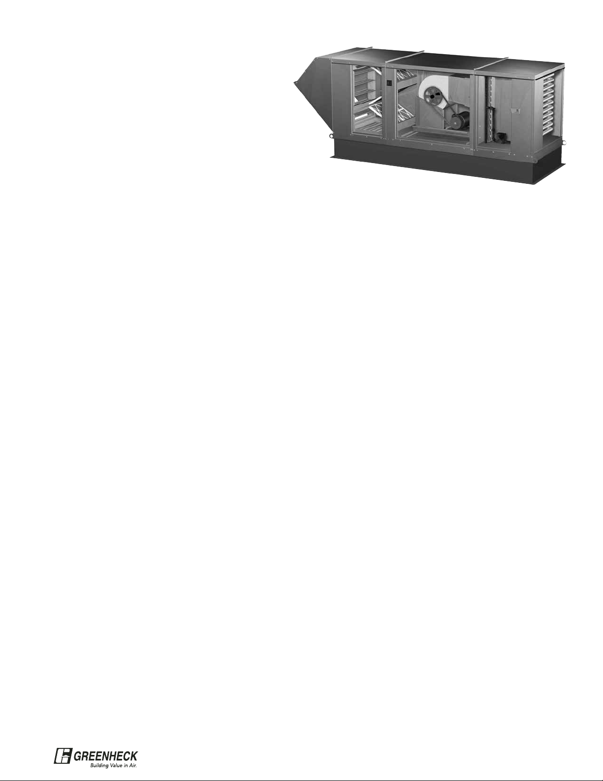
35
General: Heating and Ventilating unit shall be as
manufactured by Greenheck or approved equal provided
all specifications are met. Greenheck Model IGX-HV is
used as the basis of design. Performance shall be as
scheduled on plans.
Furnace: Indirect gas fired furnace shall be 80%
efficient, ETL Listed and have a blow through fan design.
Furnace shall be capable of operation with natural or LP
gas and have a power venting system with post purge
cycle. The heat exchanger shall be constructed of
aluminized steel or stainless steel. Standard furnace
features shall include main gas pressure regulator, main
gas valve, electronic staged controls, direct spark
ignition system, high limit and a 24 volt control
transformer. Furnace shall be insulated and have double
wall construction.
Temperature Control: Heating and cooling output shall
be controlled by a room thermostat to maintain desired
room temperature. Economizer control shall provide the
first stage of cooling, where specified. Furnaces shall
provide 1 or 2 stages of heat output control.
Unit Casing and Frames: All frames and panels shall
be G90 galvanized steel. Where top panels are joined
there shall be a standing seam to insure positive weather
protection. All metal-to-metal surfaces exposed to the
weather shall be sealed, requiring no caulking at job site.
All components shall be easily accessible through
removable doors.
Insulation: Models provided with a mixing box shall be
insulated from the return section through to the supply
discharge. Insulation shall be in accordance with NFPA
90A and tested to meet UL 181 erosion requirements.
Double wall shall be provided if specified.
Fan Section: Centrifugal fans shall be double width,
double inlet. Fan and motor shall be mounted on a
common base and shall be internally isolated. All blower
wheels shall be statically and dynamically balanced.
Ground and polished steel fan shafts shall be mounted in
permanently lubricated ball bearings (up to size 118) or
ball bearing pillow blocks (size 120 and larger). Bearings
shall be selected for a minimum (L10) life in excess of
100,000 hours at maximum cataloged speeds.
Motors and Drives: Motors shall be energy efficient,
complying with EPACT standards, for single speed ODP
and TE enclosures.
Motors shall be permanently lubricated, heavy duty type,
matched to
the fan load and furnished at the specified voltage,
phase and enclosure. Drives shall be sized for a
minimum of 150% of driven horsepower. Pulleys shall be
cast and have machined surfaces, 10 horse power and
less shall be supplied with an adjustable drive pulley.
Electrical: All internal electrical components shall be
prewired for single point power connection. All electrical
components shall be UL listed, recognized or classified
where applicable and wired in compliance with the
National Electrical Code. Control center shall include
motor starter, control circuit short circuit protection,
control transformer for 24 VAC circuit, integral
disconnect switch and terminal strip. Contactors, Class
20 adjustable overload protection and single phase
protection shall be standard.
Filter Section: Filters shall be mounted in a V-bank
arrangement such that velocities across the filters do not
exceed 550 feet per minute. Filters shall be easily
accessible through a removable access panel.
Weather Hood: Weather hood shall be constructed of
G90 galvanized steel, with stationary louvered intake with
2 inch aluminum mesh filters.
Mixing Box: Mixing box shall contain outside air and
return air dampers with low leak, pressure activated,
extruded vinyl blade seals, stainless steel jamb seals,
Belimo actuator and 30% efficient pleated filters in a Vbank arrangement. The mixing box shall modulate the
amount of outdoor and return air by use of dampers.
Input signal for return damper shall be from
potentiometer, 2-10 volt signal, 4-20 mA signal or manual
quadrant controller, or economizer.
Cooling Coil: Direct expansion (DX) or chilled water coil
shall be factory tested and rated in accordance with ARI
410. Coils shall have copper tubes with permanently
expanded aluminum fins, 12 fpi or less. DX coils shall be
equipped with distributors to receive expansion valves at
the liquid connections. Drain pans shall extend at least 12
inches downstream of coil and be sloped to drain
connection.
IGX-HV Typical Specifications
®
Page 36

Greenheck warrants this equipment to be free from defects in material and workmanship for a period
of one year from the purchase date. Any units or parts which prove defective during the warranty
period will be replaced at our option when returned to our factory, transportation prepaid. Motors are
warranted by the motor manufacturer for a period of one year. Should motors furnished by Greenheck
prove defective during this period, they should be returned to the nearest authorized motor service
station. Greenheck will not be responsible for any removal or installation costs.
As a result of our commitment to continuous improvement, Greenheck reserves the right to change
specifications without notice.
P.O. Box 410 • Schofield, WI 54476-0410 • Phone (715) 359-6171 • greenheck.com
Our Warranty
Heating Type
Model
Airflow Range
(CFM)
Max Heater Size
(MBH)
Airflow Options Max Cooling Volume (CFM)
Direct Gas
Natural Gas LP VAV/2-Speed Recirculation Evaporative DX Chilled Water
DG 800 - 15,000 1,600 1,400 12,000
DGX 800 - 48,000 4,800 4,200 X X 46,000 11,000 11,000
TSU 20,000 - 64,000 7,000 6,000 X X 60,000
VSU 800 - 64,000 7,000 6,000 X X
Indirect Gas
IG 800 - 7,000 400 (input) X 7,000
IGX 800 - 23,000 2,400 (input) X X 19,000 11,000 11,000
IG-HV 800 - 7,000 400 (input) X
IGX-HV 800 - 16,000 1,200 (input) X 14,000 11,000 11,000
Steam
MSX 1,000 - 21,000 1,900 MBH Call Factory X 21,000 11,000 11,000
Hot Water
MSX 1,000 - 21,000 1,600 MBH Call Factory X 21,000 11,000 11,000
Electric
MSX 800 - 21,000 180 kW Call Factory X 21,000 11,000 11,000
Untempered
KSFD 400 - 2,100
KSFB 1,000 - 10,500 X
KSF 800 - 12,000 X
MSX 800 - 48,000 X X
TSF 20,000 - 64,000 X
Make-Up Air Product Selection Guide
Model DG
Model IG
Model MSX
Model DGX
Model IGX
Model TSU
Model VSU
Model IG-HV
Model IGX-HV
Model KSF-D
Model KSF
Indirect Gas-Fired Tech Guide Rev1 May 2005
Copyright © 2005 Greenheck Fan Corp.
 Loading...