

Page 1
Centrifugal Roof Downblast Exhaust Fans
• General Clean Air • Light Contaminants
• Seismic • High Wind
Models G and GB
July
2009
Page 2
Centrifugal Roof Exhaust Fans
Spun Aluminum • Downblast
Greenheck models G and GB centrifugal roof exhaust fans
provide the industry’s best performance and durability for
general clean air applications.
• Broadest performance in the industry, up to 3.25 in. wg
(810 Pa) and 45,000 cfm (76,500 m3/hr).
• Most advanced motor cooling of any fan in its class.
• Performance as cataloged is assured. All fan sizes are
tested in our AMCA Accredited Laboratory, and all
models are licensed to bear the AMCA sound and air
performance seals.
• UL Listed for electrical.*
• Greenheck subjects these products to extensive life
testing, assuring you that the fans will provide years of
reliable performance.
Greenheck Fan Corporation certifies that the Models G,
and GB fans shown herein are licensed to bear the AMCA
Seal. The ratings shown are based on tests and procedures
performed in accordance with AMCA Publication 211 and
Publication 311 and comply with the requirements of the
AMCA Certified Ratings Program. The certified ratings for
Models G, and GB are shown on pages 17 to 55.
G and GB models are listed for electrical
(UL/cUL 705) File no. E40001
*UL/cUL is optional and must be specified
Model
Model Comparison
Mounting Airfl ow Application Drive Type
G
GB
Roof Curb
Exhaust
General/Clean Air
Maximum Operating
Temperature
130°F
(54°C)
180°F
(82°C)
High Wind (150 mph)
Belt
Direct
Performance
/hr)
3
Maximum Volume
cfm (m
4,300
(7,306)
44,700
(75,946)
Maximum Static
Pressure
in. wg (Pascals)
1.0
(249)
3.25
(810)
2
Page 3
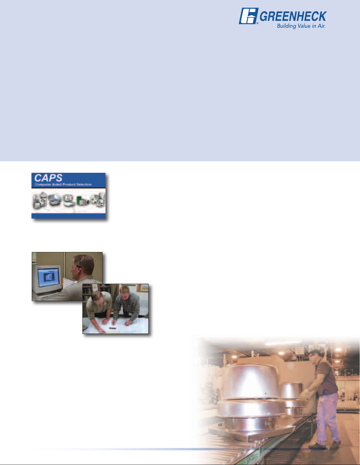
Table of Contents
Model Comparison . . . . . . . . . . . . . . . . . 2
Codes & Certifications . . . . . . . . . . . . . . 4
Applications:
General Clean Air . . . . . . . . . . . . . . . . . 4
Seismic . . . . . . . . . . . . . . . . . . . . . . . . . 5
Vari-Green Motors . . . . . . . . . . . . . . . . 5
High Wind & Hurricane . . . . . . . . . . . . 6
Roof Curbs . . . . . . . . . . . . . . . . . . . . . . 7
Standard Construction Features . . . . .8-9
Options & Accessories . . . . . . . . . . .10-11
Leading Edge Technical Support
When product and IOM (Installation, Operation and Maintenance Manual)
information is needed, our products are supported by the industry’s best product
literature, electronic media, and Computer Aided Product Selection (CAPS)
program. You’ll also fi nd this information on our web site at www.greenheck.com
Typical Installations. . . . . . . . . . . . . .12-13
Severe-Duty Curbs Anchoring . . . . .14-15
Performance and Dimensions:
Model Number Code . . . . . . . . . . . . . 16
Direct Drive (by size). . . . . . . . . . . . .17-26
Belt Drive (by size) . . . . . . . . . . . . . .27-55
Typical Specifications . . . . . . . . . . . .56-59
Quick Build Programs . . . . . . . . . . . . . . 60
Warranty . . . . . . . . . . . . . . . . . . . . . . . . 60
Our national and international representative organizations provide personal service and expertise. To locate
your nearest Greenheck representative, call 715-359-6171 or visit our web site at www.greenheck.com
Outstanding Customer Service
Your local Greenheck representative has a wealth of industry and product
knowledge to answer your questions. Our representatives receive the latest
product information and can have orders processed directly
to our factory. With our direct order processing system, we
can ship orders as fast as the next day. With Greenheck’s
experienced staff, we can answer questions and provide
solutions.
World Class Manufacturing
Greenheck’s skilled production workers use cost-effective
machines and unique dies designed and built by our own engineers
to add innovative features and greater strength to our centrifugal
exhaust fans. Our advanced manufacturing processes and quality
control procedures always ensure the highest product quality. And
just to be sure you get the peace-of-mind you expect when you
specify Greenheck, our assembly inspectors test run and monitor
every fan before it leaves the factory. Results of these tests are
kept in permanent records for future reference.
3
Page 4

Codes and Certifications &
Applications: General Clean Air
Codes and Certifications
UL 705 - Power Ventilators
Intended to assure the buyer of the safety of
electrical components and connections within power
ventilators and duct fans. Limited to fans connected
to permanently installed wiring that meet NFPA 70
and the National Electric Code. Tests under this
standard relate to extremes of current, temperature,
fuses, motor windings, bearing temperatures, and
water that a fan could be subject to.
Clean Air Applications
Models G and GB
These spun aluminum fans are specifically designed
for roof mounted applications. General clean
exhaust air is discharged downward, toward the
roof surface.
• Most advanced motor cooling of any fan in
its class.
• Performance as cataloged is assured. All fan sizes
are tested in our AMCA Accredited Laboratory
and all models are licensed to bear the AMCA
Sound and Air Performance seal.
• Greenheck subjects these products to extensive
life testing, assuring you the fans will provide
many years of reliable performance.
AMCA Certied Ratings Program
Ensures that all data is accurate. The 211 test for air
performance certifies that the fan has been tested
to the appropriate AMCA standards in a licensed
test facility and that the air performance displayed
in catalogues and selection software is accurate.
The 311 test for air and sound performance certifies
that the fan has been tested to the appropriate
AMCA sound standards in a licensed facility and
that the sound performance displayed in catalogues
and selection software is accurate. AMCA Certified
Ratings Program is designed to ensure that the
products perform as stated and that a third party
organization has verified all published data for
accuracy and consistency.
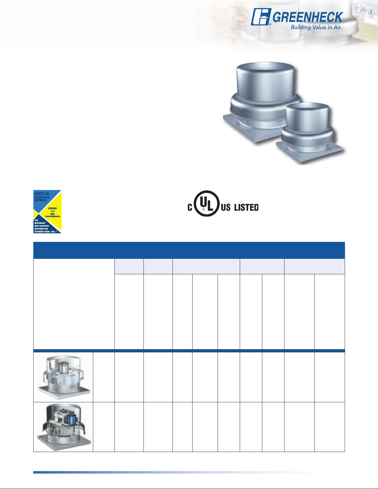
Direct Drive, G
• Typically used for short and/or low
resistance ductwork
Belt Drive, GB
• Typically used for average length and/or average
resistance ductwork
• High volume/average pressure
Belt Drive, GB-HP
• Typically used for long and/or high
resistance ductwork
• Low volume/high pressure
4
Page 5
Applications:
Seismic and Vari-Green Motor
Seismic Applications
Models G and GB
The International Building Code has been adopted
on the state and local level throughout most of the
fi fty states. The adoption of this code has resulted in
the adherence of buildings, along with electrical and
mechanical components, to new previsions in the
code. In particular, there is an emphasis on seismic
compliance. As an industry leader, Greenheck
introduces the fi rst seismic compliant centrifugal
roof exhaust fan available for general clean
air applications.
Greenheck offers products certifi ed for the worst
plausible seismic event that would be found on the
IBC Spectral Response Map. Models G and GB are
rated for seismic design categories A-F, which allows
Greenheck to provide a seismic ventilation solution
regardless of the location in the country.
Rigorous Testing
• Third-party FEA (Finite Element Analysis) by
licensed Professional Engineers
• Tested in Accordance with ICC ES AC-156
acceptance criteria utilizing shake table testing
to simulate the worst case scenario.
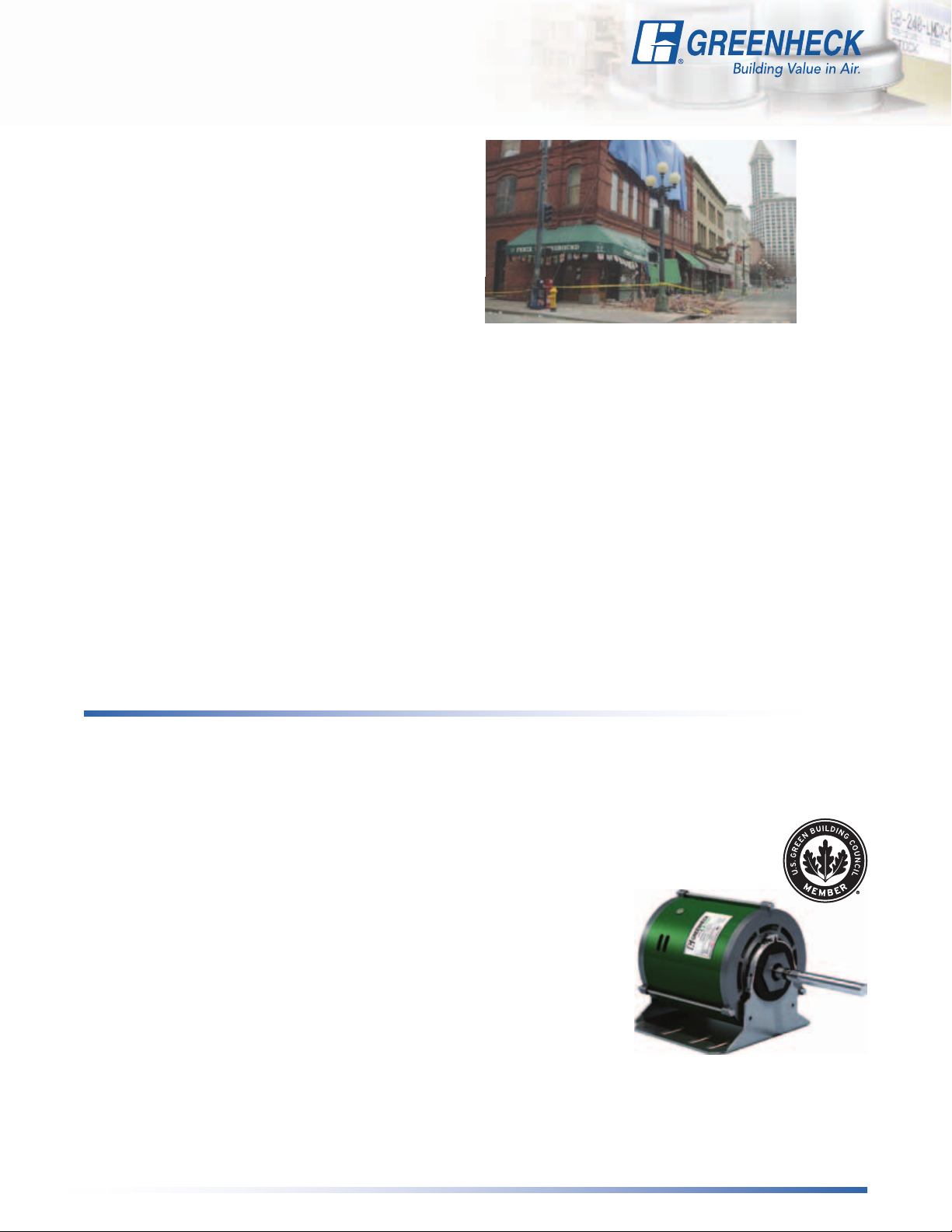
Seattle, WA, 03/05/01 -- Damage in Pioneer Square from the
02/28 earthquake. FEMA/Photo by: Liz Roll/FEMA News Photo
State P.E. Calculations
Models have been reviewed by licensed
Professional Engineers to ensure they conform to
the requirements of ASCE 7-05 Minimum Design
Loads for Buildings and Other Structures and the
International Building Code.
How Can Greenheck Provide
a Seismic Solution?
While adhering to rigorous testing standards,
Greenheck Fan Corporation is striving to provide a
comprehensive selection of equipment to address
the HVAC industry’s seismic needs. The offerings
cover all soil site classes. For the simplifi cation of the
submittal process, the consulting engineer simply
needs to specify seismic compliant equipment.
Vari-Green Motor
Applications
Model G available in sizes 080 thru 131
The Greenheck Vari-Green motor blends technology,
controllability and energy-effi ciency into a low
maintenance package changing the way the
industry designs, specifi es and operates air
movement equipment.
The Vari-Green motor is the industry’s fi rst fully
controllable fractional horsepower (hp) motor
available in 1/4 hp, 1/2 hp and 3/4 hp. The VariGreen motor is cost-effective with less than one-year
payback. The motor is available with a potentiometer
speed control dial mounted right on the motor to
make system balancing a breeze. It can also be
provided with 0-10 volt control wire inputs for easy
integration into a Building Automation System (BAS)
or any controller that can output a 0-10 volt signal.
Greenheck is leading the charge in the LEED and
Green Building initiative. Greenheck became one
of the fi rst manufacturers in the Air Movement and
Control industry to join the LEED/green movement
when they joined the United States
Green Building Council (USGBC) in
2005. Greenheck has been actively
researching qualifi cation requirements
for our products to
meet LEED credits
and prerequisites.
The Vari-Green
motor signifi cantly
helps qualifi cation
efforts for the
Energy and
Atmosphere credits
and prerequisites;
specifi cally credit one, Optimize Energy Performance
and prerequisite two, Minimum Energy Performance.
For more detailed information refer to the Vari-Green
Motor brochure.
5
Page 6
Applications:
High Wind and Hurricane
High Wind and Hurricane
Models G and GB
Greenheck is leading the High Wind Standard for roof top fans and ventilators.
Forceful winds and wind-borne debris are the cause of most hurricane damage.
Hurricane winds start at 75mph. At speeds over 150mph, wind can exert a
force of 75poundspersquarefoot of pressure or over 900pounds on a fan and
curb. Forceful winds are not the only problem, wind-borne debris can also cause
detrimental effects to objects and structures. High winds and extreme forces are
the cause of most storm damage. By analyzing calculations, computer simulations,
actual testing, and other standards—Greenheck developed the High Wind Standard.
Protocols designed to protect against wind-borne debris and severe wind loads:
Structural
Performance Load
Miami-Dade
County Test
Protocols
Miami-Dade NOA
Numbers
Texas Department
of Insurance
State Licensed
P.E. Calculations
Certified
Independent
Third-Party
Testing
A static load that is 1.5times the design load (91.5 pounds per square foot of pressure)
is applied both positively and negatively to simulate wind force loads in each direction.
Structural Performance per Dade County Protocol TAS-202 (ASTM-E330).
Greenheck has gone the extra mile and worked with Miami-Dade County to design
a High Velocity Hurricane Zone standard for rooftop fans. The model USGF has
become the first rooftop fan certified and approved by the Miami-Dade Building Code
Compliance office and Texas Department of Insurance for use in hurricane zones.
The certifications can be viewed on the Miami-Dade County Web site under the NOA
numbers listed below. Models G and GB are the first downblast aluminum fans in the
industry that have received a Miami-Dade NOA for high wind (150 mph) and hurricane
zones. Miami-Dade NOA 08-0519.02 for models G and GB.
The certifications can be viewed on the Texas Department of Insurance Windstorm
Web site under TDInumberRV-42.
Structural calculations performed by a licensed Professional Engineer (P.E.) on models
G and GB include Finite Element Analysis (FEA) and a stamped P.E. report of the fans
compliance to ASCE 7-02 Minimum Design Loads for Buildings and Other Structures
Standard and the Florida Building Code. The ASCE 7-02 Standard meets the IBC,
Florida and Miami-Dade codes. The models have been proven to withstand winds in
excess of 150 mph (61 psf).
Each of the Greenheck models have been subjected to extensive testing procedures.
The G and GB have been certified by an independent third party to the ASTM E-330
Static Pressure Difference Standard, Florida Building Code Test Protocol
TAS-201 (large missile impact), 202 (static pressure difference) and 203 (cyclic
pressure) Static Pressure Difference.
Computational
Fluid Dynamics
(CFD)
Finite Element
Analysis (FEA)
6
All Greenheck high wind models have been analyzed using Computational Fluid
Dynamics (CFD). CFD is computer software designed to simulate the flow of high
speed (150 mph) winds over the surface of objects. The software records the force
profile exerted on the fan so it can be utilized in Finite Element Analysis (FEA).
Utilizing the results from CFD analysis Greenheck can
accurately predict the stress, strain, and deflection resulting
from high wind loads. Greenheck high wind units have been
proven to withstand 150 mph winds through Finite Element
Analysis utilizing CFD results.
Page 7
Applications: Severe-Duty Roof Curbs
for High Wind and Hurricane
High-wind and severe-duty roof curbs are provided
as standard with models G and GB. The severe-duty
roof curb models can ship separately to allow
for final finishing of the roof prior to the fan
arrival and installation.
Model GPF — This roof curb is specifically
designed for high wind applications up to 150 mph
(61 psf), used on fan models G and GB. Standard
height is 12inches (305mm), fully-welded straight
sides with a 5-inch flashing flange. GPF is available
up to 24inches (460mm) in height to meet greater
height requirements.
Models SD and SDP — The severe-duty curbs
are specifically designed for high wind applications
up to 150mph and used on models G and GB fans.
Model SD is for use on flat roofs and model SDP
for pitched roofs. They are attached directly to the
building structure with extremely high structural
design load requirements. Maximum design load is
130psf. The severe-duty curbs are 12gauge
coated steel with a 13⁄4-inch lip on the top and a
4-inch flange on the bottom. Available heights
include 12–24inches. Heights greater than
18inches are reinforced in the interior with
12gauge x 2-inch angles.
Mounting details for the roof curb to the roof
substrate and the fan to the curb are illustrated
on the following pages and are included with each
model G and GB installation manual.
7
Page 8

Standard Construction
Features
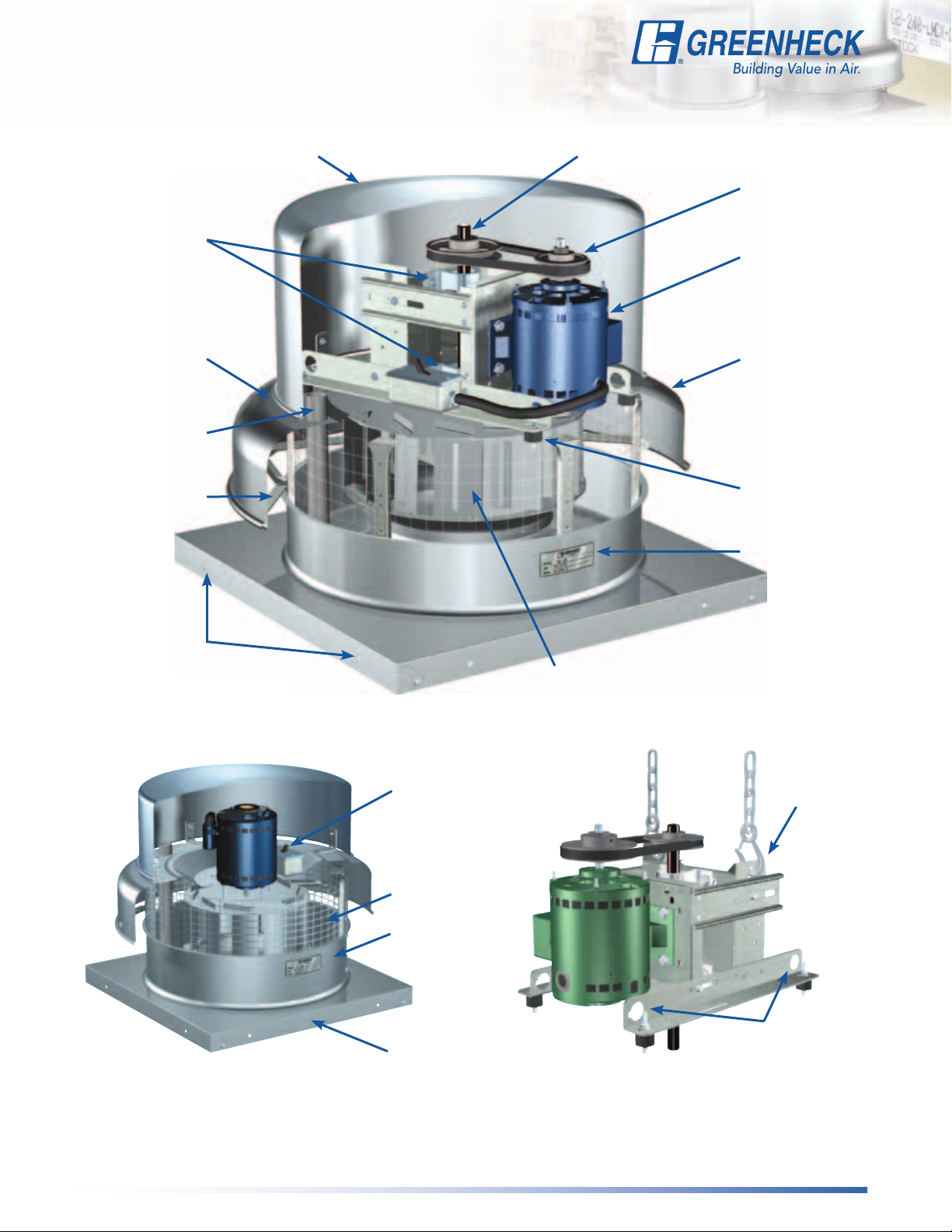
Standard Construction Features
An aluminum, backward-inclined, non-overloading centrifugal wheel is utilized to generate
Wheel
Disconnect
Switch
Fan Shaft
Bearings
Motor Carefully matched to the fan load and is mounted out of the airstream.
Motor Cover
Motor Cooling
Lifting Points Various lifting points are located on the drive frame and bearing plate (on select sizes).
True Vibration
Isolation
Drive Assembly
high-efficiency and minimal sound. Wheel cones are carefully matched to the venturi
for maximum efficiency. Each wheel is robotically welded and statically and dynamically
balanced for long life and quiet operation.
NEMA-1 switch is factory mounted and wiring is provided from the motor as standard
(other switches are available). All wiring and electrical components comply with the
National Electric Code (NEC) and are either UL Listed or Recognized.
Precisely sized, ground and polished so the first critical speed is at least 25% over
the maximum operating speed. Where the shaft makes contact with bearings, close
tolerances result in longer bearing life.
100% factory tested and designed specifically for air handling applications with a
minimum L
Constructed of aluminum, machine-punched, and attached with stainless steel hardware
for easy removal and access to motor compartment and drive assembly.
Cooling fins located on top of the fan wheel draw outside air through a large space
between the fan shroud and the motor cover directly into the motor compartment.
Positive motor cooling with fresh air results in maximum motor life.
Vibration isolators, with no metal-to-metal contact, support the drive assembly and wheel
for long life and quiet operation.
Belts, pulleys, and keys are oversized 150% of driven horsepower. Machined cast pulleys
are adjustable for final system balancing. Belts are static-free and oil-resistant.
life in excess of 100,000 hours (L 50 life of 500,000 hours).
10
G and GB
Lower Windband
Curb Cap
Internal Conduit
Chase
Nameplate Permanent stamped aluminum plate for exact model and serial number identification.
Galvanized
Birdscreen
Fan Shroud
Mounting Holes Curb cap has prepunched mounting holes to ensure correct attachment to the roof.
Internal Supports
Roof Curb
Applicable to fans with high wind option only.
*
Heavy-gauge aluminum with formed edges for added strength and provides
weather resistance.
Curb cap (with integral deep spun venturi) is constructed of aluminum and is one-piece for a
weather-tight fit.
A large diameter conduit for installing electrical wiring through the curb cap into the
motor compartment.
Rigid wire protects the fan discharge from birds and small objects.
One-piece, heavy-gauge aluminum with a rolled bead for extra strength directs exhaust
air downward.
Heavy-gauge supports and bracing are added for additional strength to withstand
a wind of 150 mph (61 psf
High-wind load fans are certified with one of two Greenheck high-wind roof curbs.
Standard 12-inch (305 mm) in height GPF curb has a 5-inch (127 mm) flashing flange. Roof
curbs ship separate for field installation with attachment details provided.
).
*
*
8
Page 9
Standard Construction Features
Models G and GB
Bearings
Motor Cooling
Space
Conduit Chase
Shroud Brace
Motor Cover
Fan Shaft
Drive Assembly
Motor
Fan Shroud
True Vibration
Isolators
Nameplate
Mounting Holes
Disconnect
Switch
Birdscreen
Lower
Windband
Curb Cap
Wheel
Bearing Plate
Lifting Points
Drive Frame
Lifting Points
9
Page 10
Options and
Accessories
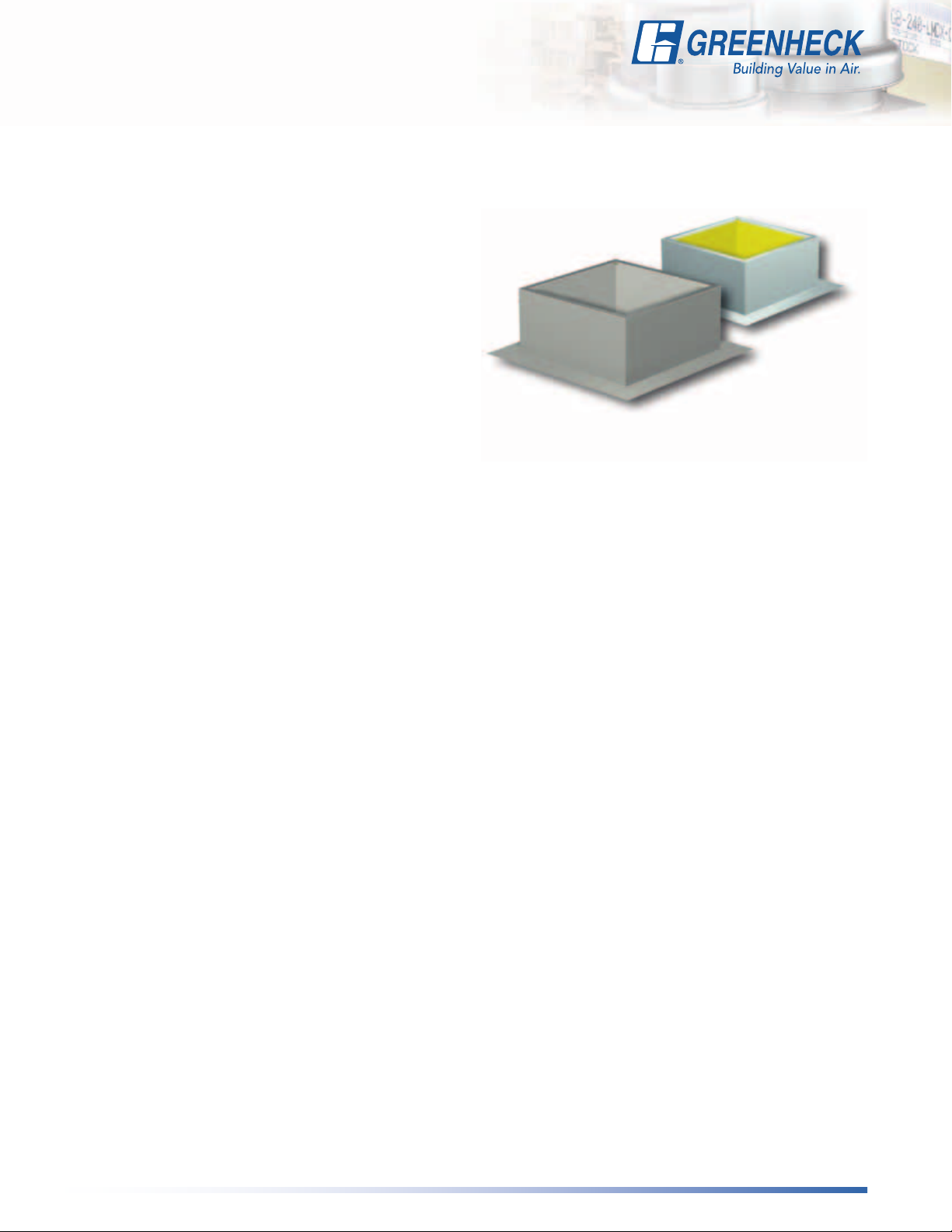
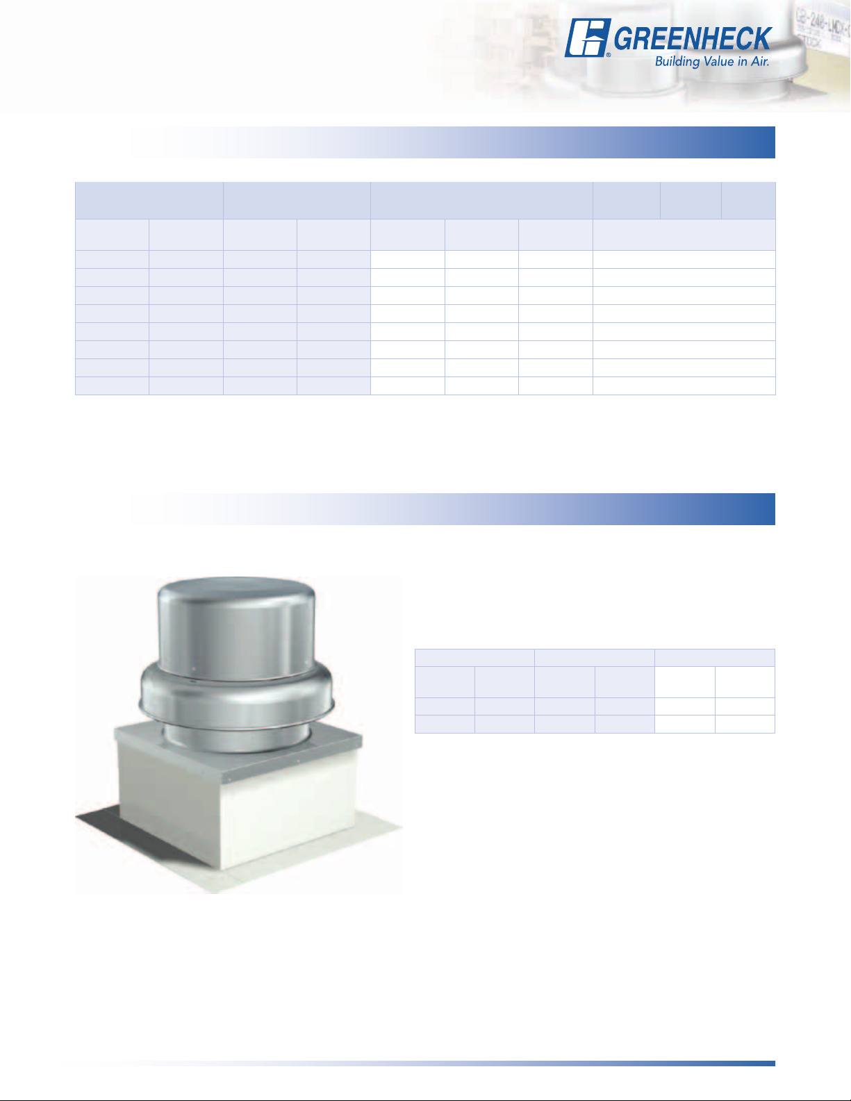
Roof Curbs
Prefabricated roof curbs
reduce installation time
and costs by ensuring
compatibility between
the fan, the curb and roof
opening. All curbs are
insulated with fiberglass.
A wide variety of roof
curbs are available, including: flanged, pitched and
sound-absorbing. For more information on severeduty curbs refer to the information on page 7.
Hinged Curb Cap with Cables (Field Installed)
Mounted to the curb cap, allows entire fan to tilt
away from curb for access to wheel and ductwork.
Includes restraint cables.
Hinged Base (Factory Mounted)
Allows for easy maintenance.
Hinge and restraining cables are
factory mounted to a subbase
attached directly to curb without
additional height added.
Curb Seal
Rubber seal between fan and curb to assure proper
sealing when attached to a curb.
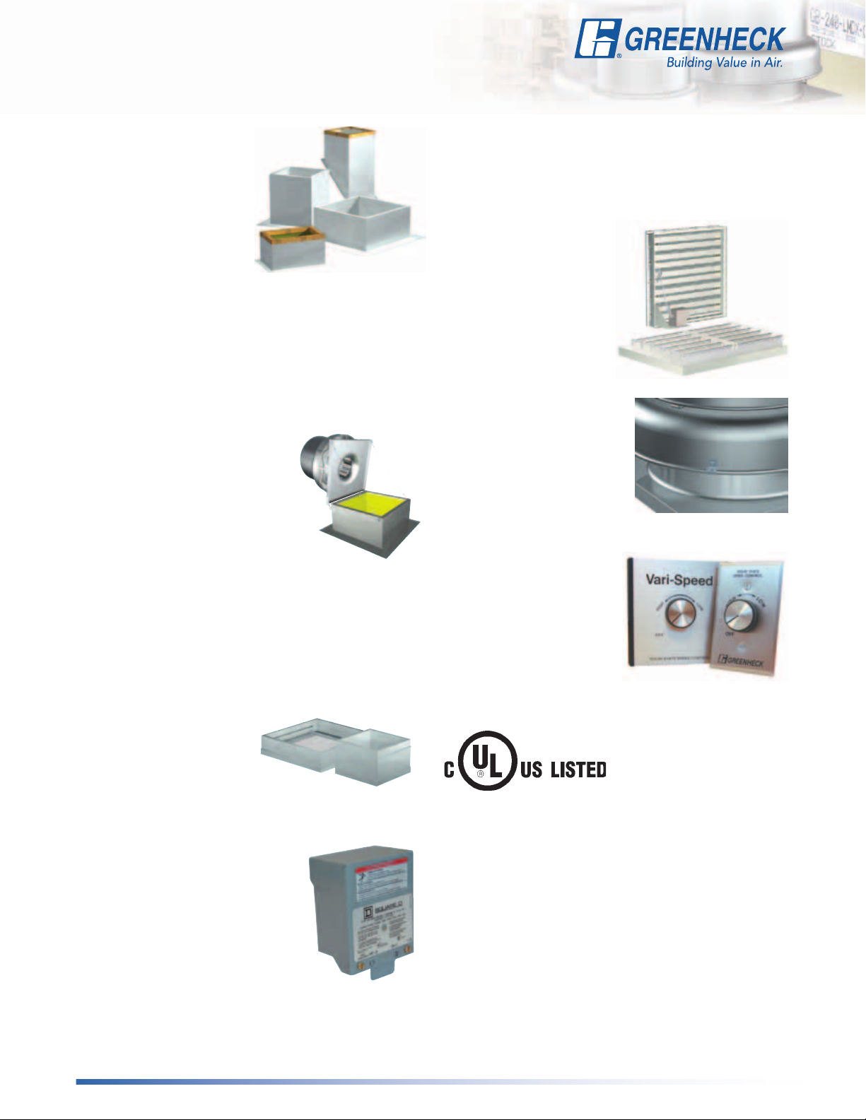
Curb Extensions
Extensions raise the fan discharge above the roofline
and provide an accessible mounting location for
dampers. Insect screen
bases, constructed with
a removable fine mesh,
are recommended for
applications where insect
entry must be prevented.
Disconnect Switches
A wide selection of NEMA rated
switches are available for positive
electrical shutoff and safety,
including: dust-tight, rainproof,
and corrosion-resistant.
Switches may be internally
or externally mounted.
Birdscreen
Galvanized mesh is standard,
optional aluminum or stainless steel rigid wire
are also available.
Dampers
Designed to prevent
outside air from entering
back into the building
when fan is off. Includes
gravity and motorized
dampers. Damper sizes
are shown on each
performance data page.
Tie-Down Points
Four brackets located on
the shroud for securing
the fan in high wind
applications. Cables and
anchors by others.
Speed Controllers
Available for use with
shaded pole and
permanent split capacitor
(PSC) open motors on
model G fans. They provide
an economical means of
system balancing with
direct drive fans.
UL/cUL 705
G and GB models are listed for electrical
(UL/cUL 705) File no. E40001
*UL/cUL is optional and must be specified
10
Page 11
Options and
Accessories
Coatings
A wide variety of coatings and colors are available. Greenheck
coatings and resistance charts can be found in the Performance
Coatings Commercial and Industrial Fans catalog and in our Product
Application Guide—Performance Coatings for Ventilation Products.
PRIMER
PERMATECTOR
HI-PRO
POLYESTER
The chart below shows which options and accessories are available on
Greenheck’s centrifugal roof exhaust fans.
Primer is applied at the factory to allow for final finish
in the field.
Permatector™ is our standard coating. Typically used for
TM
applications that require corrosion resistance in indoor
and outdoor environments.
Hi-Pro Polyester is resistant to salt water, chemical fumes
and moisture in more corrosive atmospheres. Typically
used for applications that require superior chemical
resistance, excellent abrasion and outdoor UV protection.
This coating exceeds protective qualities of Air Dried
Heresite and Air Dry Phenolic.
Baked Enamel Decorative Coatings are heat cured
enamels applied either as wet paints or electrostatic
powders. Customers can choose from 16 standard
decorative colors or color match any color.
Options and Accessories
Roof Curbs
Hinged Curb Cap
Hinged Base
Curb Seal
Curb Extensions
Disconnect Switches
Birdscreen
Dampers
Tie-Down Points
Speed Controllers
UL 705
Coatings
Not available on units with high wind resistant construction.
*
G GB
* *
11
Page 12
Typical
Installations
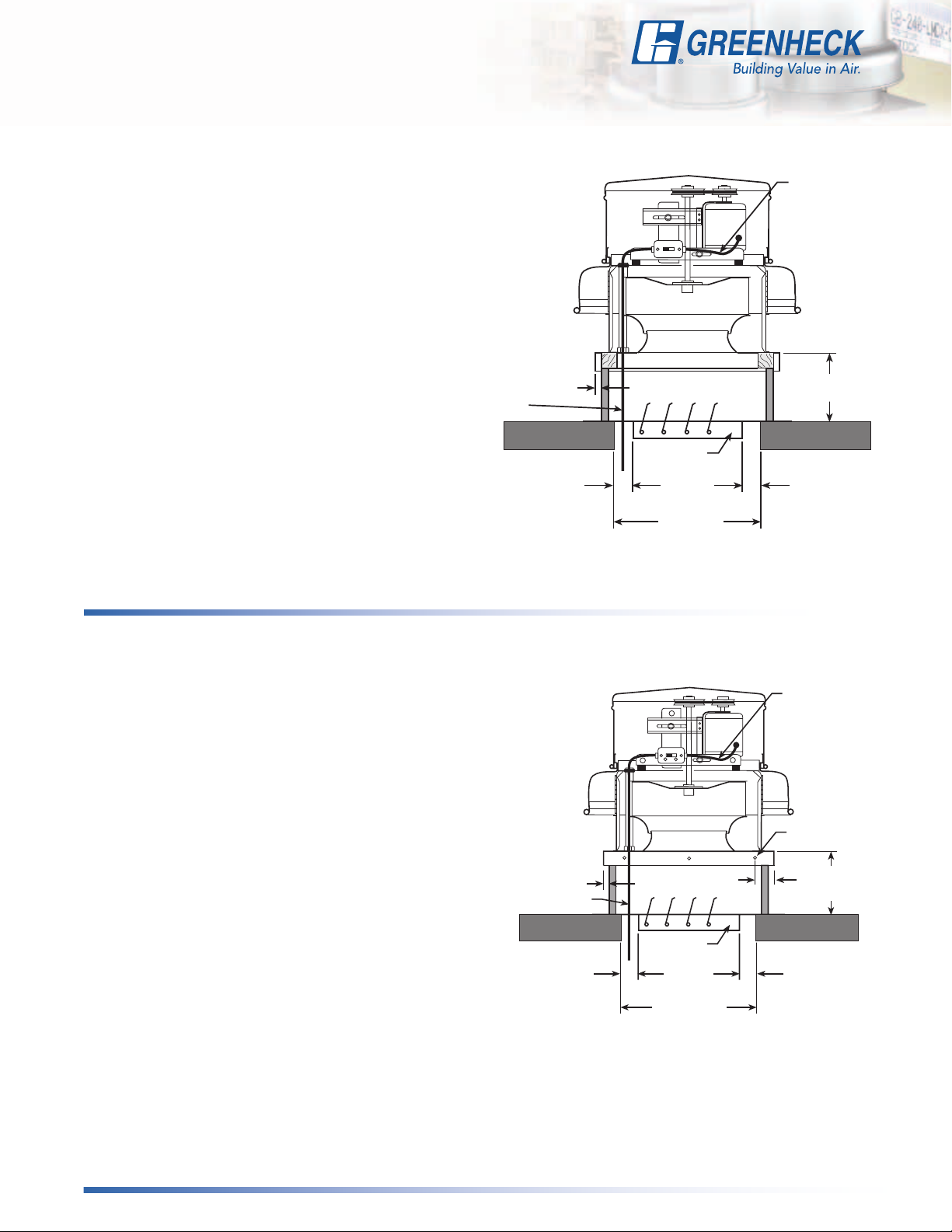
General Clean Air
Models G and GB exhaust fans are designed to meet
the needs of general clean air applications. Tests were
conducted to assure safe, rugged and reliable fans.
Due to the varying types of airstreams encountered
in commercial ventilation, system designers must
be aware of national, state, and local codes and
guidelines governing these installations. Local code
authorities should be consulted before proceeding
with any ventilation project.
• When roofing materials extend to the top of the
curb, roof curbs should be 1½ inches (3/4 inch on
each side) less than the unit curb cap to allow for
roofing and flashing.
• For recommended duct size, damper size, and
roof opening dimensions, refer to the performance
data pages.
• Installation must include a means for inspecting,
cleaning and servicing the exhaust fan.
Wiring by
Others
3/4 in.
(19 mm)
1
1
/4 in.
(32 mm)
Damper
Recommended
Duct and
Damper Size
Recommended
Roof Opening
Factory Wired
from Motor to
Disconnect
8 or 12 in.
(203 or 305 mm)
1
1
/4 in.
(32 mm)
High Wind and Hurricane Option
Models G and GB exhaust fans are designed to meet
the needs of general clean air applications. Tests were
conducted to assure safe, rugged and reliable fans.
Due to the varying airstreams encountered in commercial
ventilation, system designers must be aware of national,
state, and local codes and guidelines governing these
installations. Local code authorities should be consulted
before proceeding with any ventilation project.
• Roofing materials can extend to the top of the curb,
roof curbs should be 1-inch (25 mm) total, or 1/2inch
(13 mm) on each side, less than the unit curb cap to
allow for roofing and flashing.
• For recommended duct size, damper size and roof
opening dimensions, refer to the performance
data pages.
• Installation must include a means for inspecting,
cleaning and servicing the exhaust fan.
• See pages 14 and 15 for specific mounting instructions
1/2 in. (13 mm)
Wiring by
Others
1
1
/4 in. (32 mm)
Models G & GB
4 in. (102 mm)
From Curb Edge
Damper
Recommended
Duct and
Damper Size
Recommended
Roof Opening
Factory Wired
from Motor to
Disconnect
1/4 in. (6 mm)
Fastener
8 - 24 in.
(203 - 610 mm)
H-GPF or SD Curb
1
1
/4 in. (32 mm)
Models G & GB
Note: The typical installations shown above are recommendations based on national codes. Local authority may supersede these recommendations.
12
Page 13
Typical
Good
Poor
Counterclockwise
Airflow
Installations
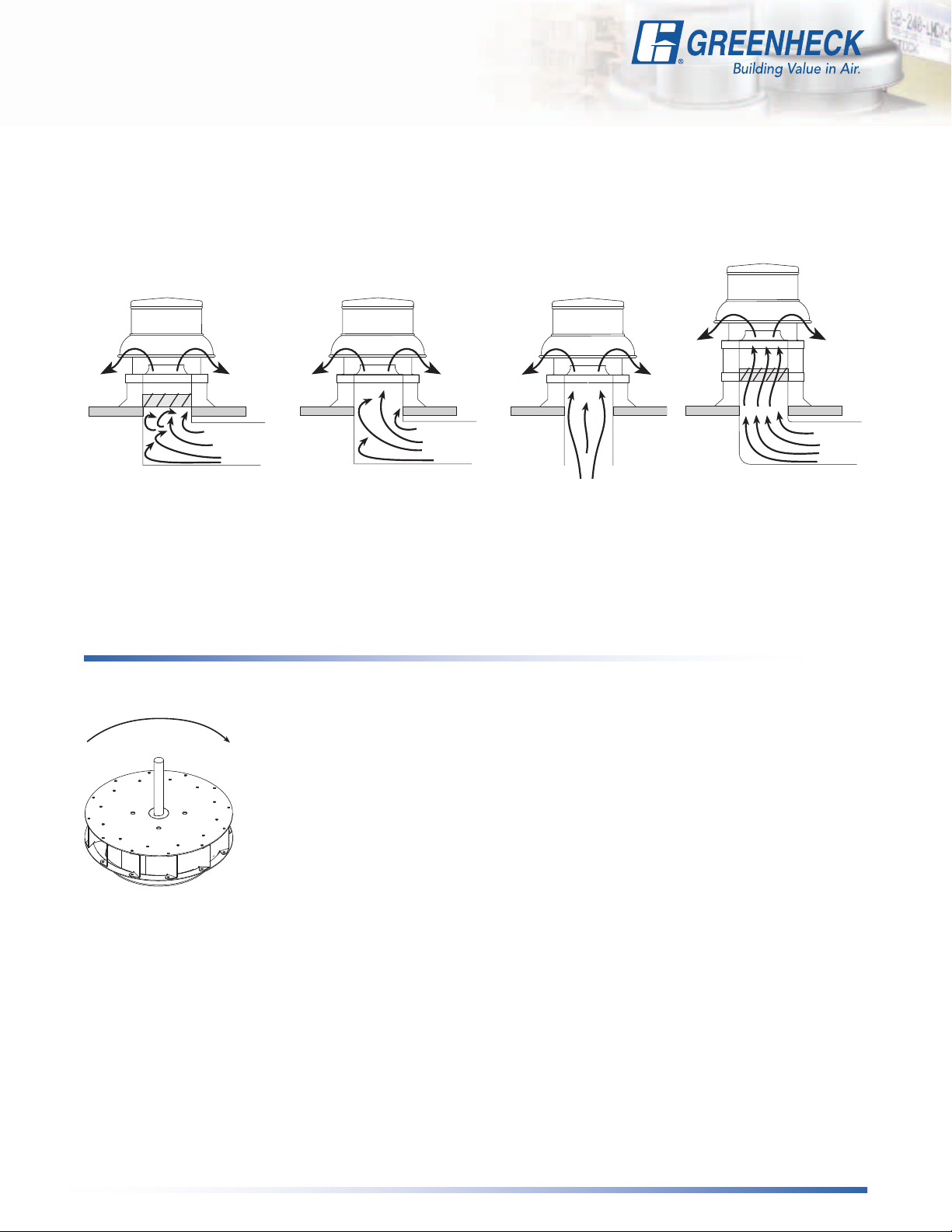
Fan Inlet Connections
In order to assure proper fan performance, caution must be exercised in fan placement and connection to
the ventilation system. Obstructions, transitions, poorly designed elbows, improperly selected dampers, etc.,
can cause reduced performance, excessive noise, and increased mechanical stress. For performance to be
as published, the system must provide uniform and stable airflow into the fan.
Good
Poor
Dampers must open
fully. Use motorized
dampers in low
airflow applications
to reduce losses.
Wheel Rotation
Direction of rotation is very critical. Rotation in the wrong
direction will result in excessive horsepower, possible motor
burnout, and increased noise levels. Check rotation by
energizing the unit only momentarily. The rotation should
be the same as the rotation decals affixed to the unit and is
clockwise when viewed from the top of the unit.
Poor
Avoid sharp turns or
entrance conditions
which cause uneven
flow. Use turning vanes
in elbows to reduce
adverse effects.
Good
Provide uniform
airflow at fan inlet
to assure optimum
performance.
Provide uniform airflow
at fan inlet and through
the damper to assure
optimum performance.
Clockwise
13
Page 14

Severe-Duty Curbs Anchoring:
Hurricane and Seismic Fans
Concrete Deck Anchoring
Outside of Roof Curb
1 inch (25 mm) less
than Fan Curb Cap
8 to 24 inches (203 to 610 mm)
GPF, SD, or SDP curb or
equivalent by others.
Minimum concrete
strength of 2000 PSI
Minimum 5 inches
(127 mm) edge distance
1-inch (25 mm) insulation
Roof opening
5 inches (127 mm)
Mounting flange
Outside flange
Use 3/8 inch (10 mm) expansion anchor or
equal into concrete.
Fasteners one on each corner as detailed.
Each side at center of unit as required.
1
2
⁄2 inches (64 mm)
Minimum embedment
Center fasteners
on flange
1¼ inch
(32 mm)
1¼ inch
(32 mm)
Wood support member
nominal 4 x 4, 6, 8
14
Metal Building/Steel Deck Anchoring
Outside of Roof Curb
1 inch (25 mm) less
than Fan Curb Cap
8 to 24 inches (203 to 610 mm)
GPF, SD, or SDP curb or
equivalent by others.
Roof Truss
1-inch (25 mm) insulation
Roof opening
Minimum 12 gauge steel
5 inches (127 mm)
Mounting flange
Outside flange
Wood Deck Anchoring
Outside of Roof Curb
1 inch (25 mm) less than
Fan Curb Cap
8 to 24 inches (203 to 610 mm)
GPF, SD, or SDP curb or
equivalent by others.
Wood decking
1-inch (25 mm) insulation
Roof opening
5 inches (127 mm)
Mounting flange
Outside flange
Use 1/4-14 self-drilling screws or equal.
Fasteners one on each corner as detailed.
Each side at center of unit as required.
Corrugated roof deck
Center fasteners
on flange
Use 3/8 inch lag screws or equal into
minimum No. 1/No. 2 southern pine
wood support.
Fasteners one on each corner as detailed.
Each side at center of unit as required.
3 inches (76 mm)
Minimum embedment
Center fasteners
on flange
Corner Detail for
all Severe Duty
Deck Anchoring
Page 15
Severe-Duty Curbs Anchoring:
Hurricane and Seismic Fans
Required Severe Duty Curb to Roof Anchoring
Seismic Hurricane Square Dimensions Concrete
G
Size
060 - 075 060 - 075 17
080 - 095 080 - 095 17(432) 12 (318) 26 (660) 2
101 - 121 071 - 131 101 - 121 071 - 131 19 (483) 14 (368) 28 (711) 2
131 - 141 141 - 161 131 - 141 141 - 161 22 (559) 18 (470) 31 (787) 3
150 150 26 (660) 18 (470) 35 (889) 3
160 - 180 180 - 200 160 - 180 180 - 200 30 (762) 20 (521) 39 (991) 3
All dimensions in inches (millimeters). *The outside ange dimension above is for the GPF curbs. Subtract 2 inches (51 mm) if the SD or SDP Curb is being used.
GB
Size
220 - 240 220 - 240 34 (864) 26 (673) 43 (1092) 3
260 - 540 260 - 300 40 (1016) 32 (826) 49 (1245) 3
G
Size
GB
Size
Fan
Curb Cap
(432) 10 (267) 26 (660) 2
Roof
Opening
Outside
Flange
Metal/
Steel
Fasteners Per Side
Required Severe Duty Fan to Curb Mounting
Models G & GB
Wood
5/16 inch (8 mm) recommended 1/4-inch fastener minimum.
Fastener quantities listed below.
Seismic Hurricane Fasteners
G
Size
060 - 141 071 - 161 060 - 141 071 - 161 3 12
150 - 180 180 - 540 150-180 180 - 300 5 20
Fasteners on each side of the fan are to be installed with one fastener
4 inches
remaining fasteners are to be equally spaced.
GB
Size
(102 mm) from each edge and one fastener centered. The
G
Size
GB
Size
Fasteners
Per Side
Total
Fasteners
15
Page 16
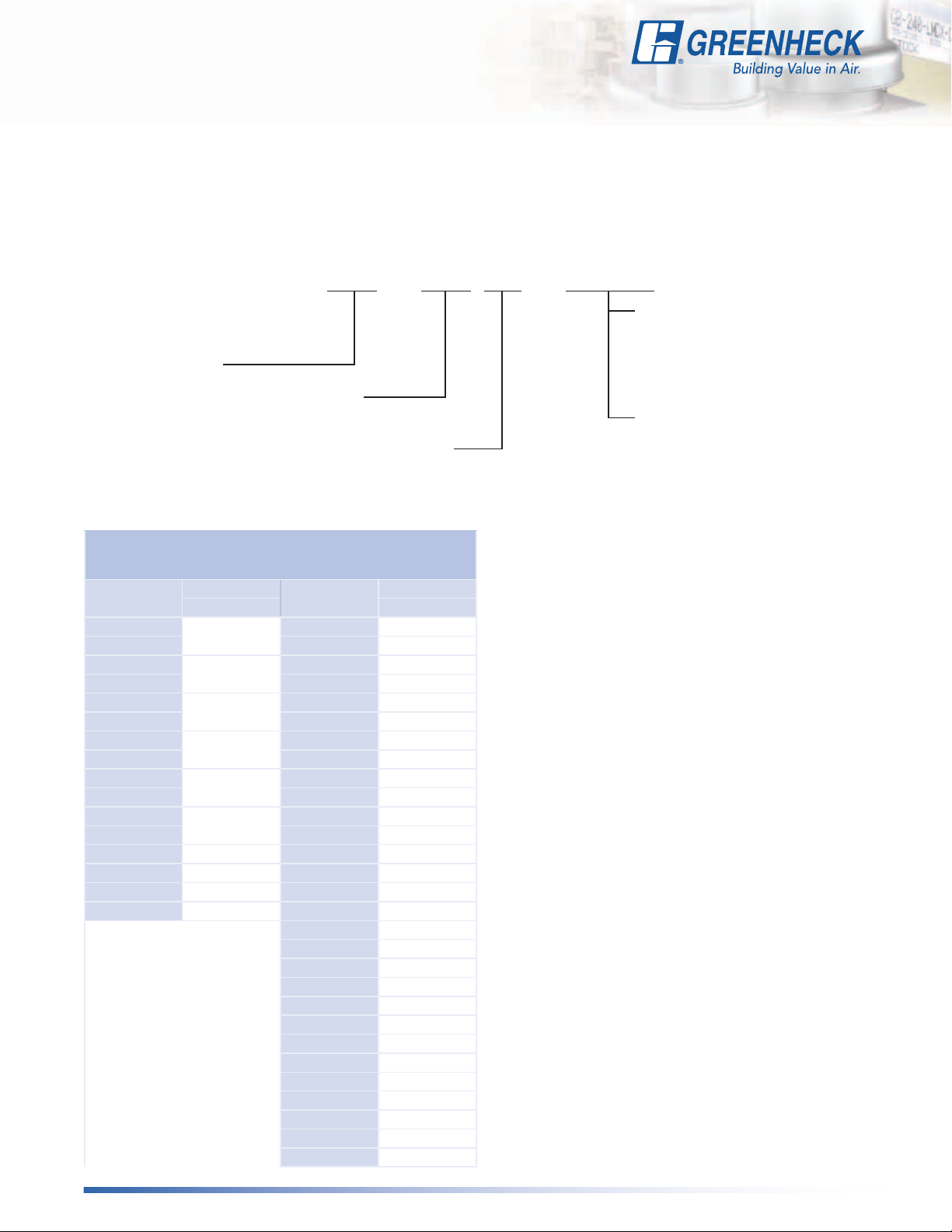
Model Number Code
The model number code system is designed to completely identify the fan. The correct code letters
must be specified to designate belt or direct drive. The remainder of the model code is determined by
the size and performance.
GB - 240 HP - 5 or A
Motor HP (Belt Drive only)
6 = 1/6 10 = 1 50 = 5
4 = 1/4 15 = 1½ 75 = 7½
Configuration
G - Direct Drive
GB - Belt Drive
Fan Size
060 through 540
Wheel Pressure Level
HP - High Pressure
3 = 1/3 20 = 2 100 = 10
5 = 1/2 30 = 3 150 = 15
7 = 3/4
Motor RPM (Direct Drive only)
A = 1725 D = 1550
B = 1140 E = 1050
C = 860 G = 1300
Performance & Dimension
Page Number by Model Size
Size
060
065 081 p. 28
070
075 101 p. 30
080
085 121 p. 32
090
095 141 p. 34
101
121 161 p. 36
131
141 180 p. 38
150 p. 23 180HP p. 39
160 p. 24 200 p. 40
170 p. 25 200HP p. 41
180 p. 26 220 p. 42
Direct Drive
G GB
p. 17
p. 18
p. 19
p. 20
p. 21
p. 22
Size
071 p. 27
091 p. 29
101HP p. 31
131 p. 33
141HP p. 35
161HP p. 37
220HP p. 43
240 p. 44
240HP p. 45
260 p. 46
300 p. 47
300HP p. 48
330 p. 49
360 p. 50
360HP p. 51
420 p. 52
480 p. 53
500 p. 54
540 p. 55
Belt Drive
16
Page 17
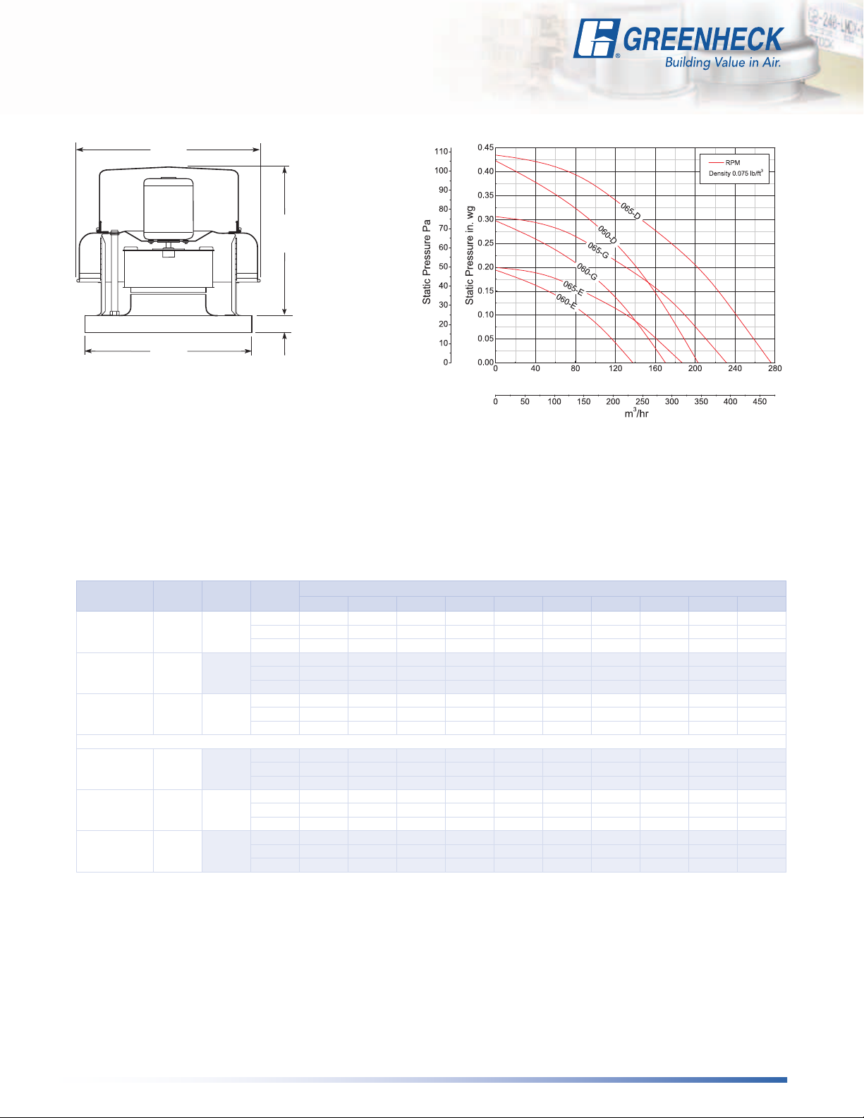
Roof Downblast - Direct Drive
G-060 and G-065
193⁄8
(492)
*121⁄8
(308)
13⁄4 (44)
17
(432)
Damper Size = 18 x 18 (457 x 457)
Roof Opening = 20 x 20 (521 x 521)
Shroud Thickness = 0.064 (1.6)
Motor Cover Thickness = 0.040 (1.0)
Curb Cap Thickness = 0.064 (1.6)
^Approximate Unit Weight = 142 lb. (64 kg)
All dimensions in inches (millimeters). *May be greater depending on motor.
^Weight shown is largest cataloged Open Drip-Proof motor.
cfm
Model
Number
060-E 1/200 1050
060-G 1/100 1300
060-D 1/60 1550
065-E 1/100 1050
065-G 1/60 1300
065-D 1/30 1550
Motor HPFan
RPM
Static Pressure in Inches wg
0 0.05 0.1 0.125 0.15 0.2 0.25 0.3 0.375 0.4
CFM 138 116 90 73 53
BHP 0.00 0.00 0.01 0.01 0.01
Sones 1.7 1.7 1.7 1.7 1.7
CFM 170 153 135 125 113 85
BHP 0.01 0.01 0.01 0.01 0.01 0.01
Sones 2.9 2.8 2.8 2.7 2.7 2.6
CFM 203 188 173 166 158 140 120 92
BHP 0.01 0.01 0.01 0.01 0.02 0.02 0.02 0.2
Sones 4.2 3.9 3.8 3.8 3.8 3.7 3.7 3.6
CFM 187 161 130 110 87
BHP 0.01 0.01 0.01 0.01 0.01
Sones 2.2 2.1 1.9 1.8 1.7
CFM 231 211 189 178 163 130 92
BHP 0.01 0.01 0.01 0.01 0.01 0.01 0.01
Sones 3.2 3.1 3.0 2.9 2.9 2.8 2.7
CFM 276 259 241 232 223 201 176 145 96
BHP 0.02 0.02 0.02 0.02 0.02 0.02 0.02 0.02 0.02
Sones 4.9 4.6 4.5 4.5 4.4 4.3 4.3 4.1 4.0
Performance certified is for installation type A: Free inlet, Free outlet. Power rating (BHP) does not include transmission losses. Performance ratings include the effects of a
birdscreen. The sound ratings shown are loudness values in hemispherical sones at 5 ft. (1.5 m) in a hemispherical free field calculated per AMCA Standard 301. Values shown
are for installation type A: free inlet hemispherical sone levels.
17
Page 18
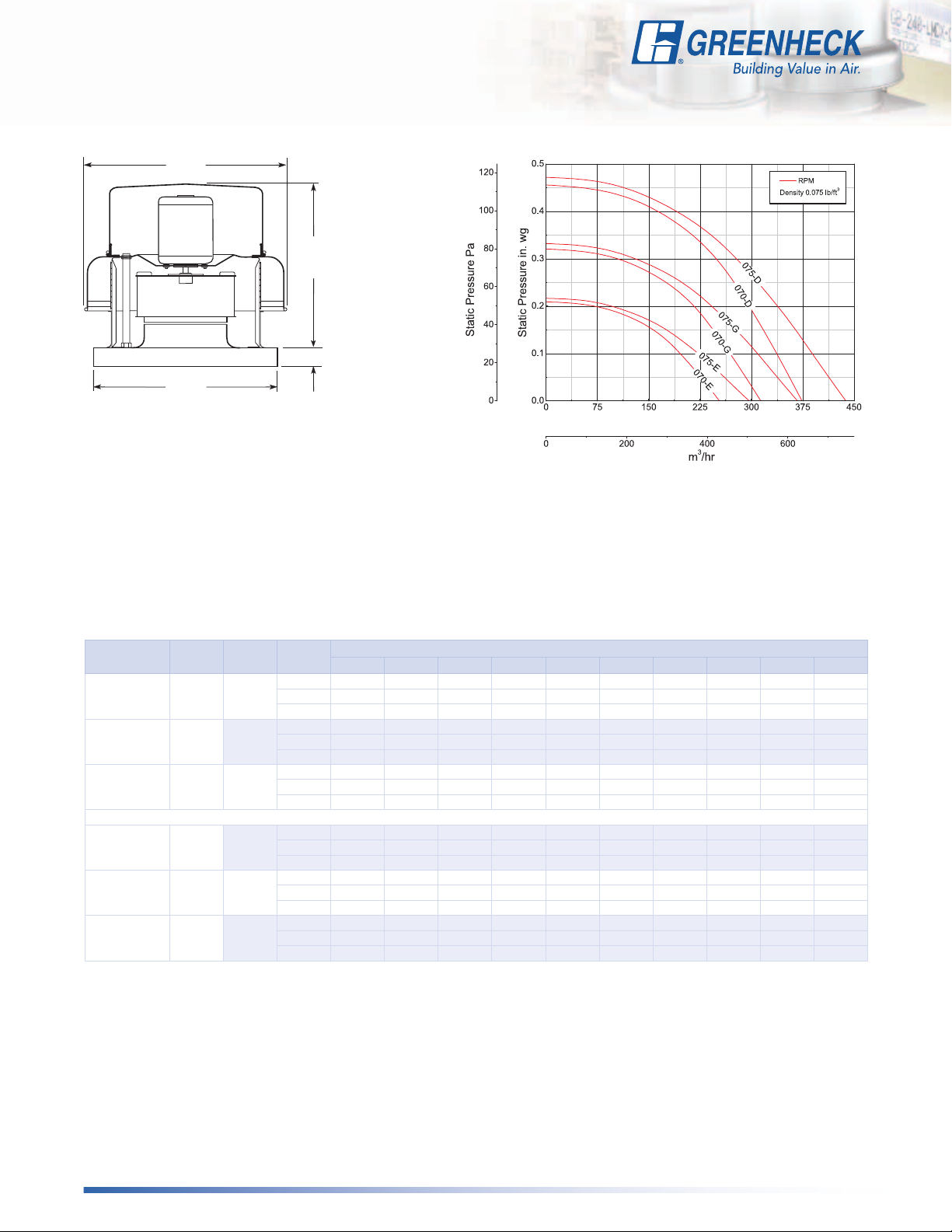
Roof Downblast - Direct Drive
G-070 and G-075
193⁄8
(492)
*121⁄8
(308)
13⁄4 (44)
17
(432)
Damper Size = 18 x 18 (457 x 457)
Roof Opening = 20 x 20 (521 x 521)
Shroud Thickness = 0.064 (1.6)
Motor Cover Thickness = 0.040 (1.0)
Curb Cap Thickness = 0.064 (1.6)
^Approximate Unit Weight = 142 lb. (64 kg)
All dimensions in inches (millimeters). *May be greater depending on motor.
^Weight shown is largest cataloged Open Drip-Proof motor.
cfm
Model
Number
070-E 1/100 1050
070-G 1/60 1300
070-D 1/30 1550
075-E 1/80 1050
075-G 1/50 1300
075-D 1/25 1550
Motor HPFan
RPM
Static Pressure in Inches wg
0 0.05 0.1 0.125 0.15 0.2 0.25 0.3 0.375 0.4
CFM 253 226 195 179 152
BHP 0.01 0.01 0.01 0.01 0.01
Sones 2.7 2.1 1.7 1.5 1.2
CFM 314 292 269 2557 244 214 171
BHP 0.01 0.1 0.02 0.02 0.02 0.02 0.02
Sones 4.1 3.7 3.4 3.3 3.2 2.9 2.6
CFM 374 356 337 327 317 297 274 244 190
BHP 0.02 0.02 0.02 0.03 0.03 0.03 0.03 0.03 0.03
Sones 5.6 5.4 5.2 5.2 5.1 4.9 4.7 4.5 4.1
CFM 297 260 222 200 176
BHP 0.01 0.01 0.01 0.01 0.01
Sones 3.6 3.1 2.9 2.8 2.6
CFM 367 338 309 293 277 241 195
BHP 0.02 0.02 0.02 0.02 0.02 0.02 0.02
Sones 4.1 3.9 3.7 3.7 3.7 3.6 3.5
CFM 438 413 389 377 364 337 309 277 214
BHP 0.03 0.03 0.3 0.04 0.04 0.04 0.04 0.04 0.03
Sones 6.1 5.8 5.6 5.4 5.3 5.1 4.9 4.9 4.8
Performance certified is for installation type A: Free inlet, Free outlet. Power rating (BHP) does not include transmission losses. Performance ratings include the effects of a
birdscreen. The sound ratings shown are loudness values in hemispherical sones at 5 ft. (1.5 m) in a hemispherical free field calculated per AMCA Standard 301. Values shown
are for installation type A: free inlet hemispherical sone levels.
18
Page 19

Roof Downblast - Direct Drive
G-080 and G-085
213⁄4
(552)
*145⁄8
(371)
13⁄4 (44)
17
(432)
Damper Size = 18 x 18 (457 x 457)
Roof Opening = 20 x 20 (521 x 521)
Shroud Thickness = 0.064 (1.6)
Motor Cover Thickness = 0.040 (1.0)
Curb Cap Thickness = 0.064 (1.6)
^Approximate Unit Weight = 142 lb. (64 kg)
All dimensions in inches (millimeters). *May be greater depending on motor.
^Weight shown is largest cataloged Open Drip-Proof motor.
cfm
Model
Number
080-E 1/40 1050
080-G 1/30 1300
080-D 1/20 1550
085-E 1/40 1050
085-G 1/30 1300
085-D 1/20 1550
Motor HPFan
RPM
Static Pressure in Inches wg
0 0.1 0.125 0.15 0.2 0.25 0.3 0.375 0.5 0.625
CFM 335 268 249 230 189 134
BHP 0.01 0.02 0.02 0.02 0.02 0.02
Sones 3.8 3.7 3.6 3.7 3.9 4.2
CFM 415 361 348 333 303 272 239 174
BHP 0.02 0.03 0.03 0.03 0.03 0.03 0.03 0.03
Sones 5.4 5.4 5.4 5.4 5.4 5.5 5.6 5.9
CFM 495 450 439 427 404 379 354 314 237
BHP 0.04 0.04 0.04 0.05 0.05 0.05 0.05 0.06 0.6
Sones 7.3 7.3 7.3 7.3 7.3 7.2 7.3 7.3 7.6
CFM 398 326 307 286 240 179
BHP 0.01 0.02 0.02 0.02 0.02 0.02
Sones 4.0 3.9 3.9 3.9 4.1 4.3
CFM 493 436 420 405 375 340 302 233
BHP 0.02 0.03 0.03 0.03 0.03 0.04 0.04 0.04
Sones 5.5 5.3 5.3 5.3 5.3 5.3 5.4 5.5
CFM 588 541 528 515 490 464 439 394 308 168
BHP 0.04 0.04 0.05 0.05 0.05 0.05 0.06 0.06 0.06 0.06
Sones 7.6 7.4 7.4 7.4 7.4 7.4 7.4 7.4 7.6 8.1
Performance certified is for installation type A: Free inlet, Free outlet. Power rating (BHP) does not include transmission losses. Performance ratings include the effects of a
birdscreen. The sound ratings shown are loudness values in hemispherical sones at 5 ft. (1.5 m) in a hemispherical free field calculated per AMCA Standard 301. Values shown
are for installation type A: free inlet hemispherical sone levels.
19
Page 20

Roof Downblast - Direct Drive
G-090 and G-095
213⁄4
(552)
*145⁄8
(371)
13⁄4 (44)
17
(432)
Damper Size = 18 x 18 (457 x 457)
Roof Opening = 20 x 20 (521 x 521)
Shroud Thickness = 0.064 (1.6)
Motor Cover Thickness = 0.040 (1.0)
Curb Cap Thickness = 0.064 (1.6)
^Approximate Unit Weight = 142 lb. (64 kg)
All dimensions in inches (millimeters). *May be greater depending on motor.
^Weight shown is largest cataloged Open Drip-Proof motor.
cfm
Model
Number
090-E 1/40 1050
090-G 1/25 1300
090-D 1/15 1550
095-E 1/30 1050
095-G 1/12 1300
095-D 1/8 1550
Motor HPFan
RPM
Static Pressure in Inches wg
0 0.1 0.125 0.15 0.2 0.25 0.3 0.375 0.5 0.625
CFM 520 441 420 398 351 293
BHP 0.01 0.02 0.02 0.02 0.02 0.02
Sones 4.0 3.9 3.9 4.0 4.1 4.2
CFM 644 580 565 549 515 478 440 373
BHP 0.03 0.03 0.04 0.04 0.04 0.04 0.04 0.05
Sones 5.4 5.4 5.4 5.4 5.4 5.5 5.5 5.6
CFM 768 714 701 688 662 633 605 557 473 338
BHP 0.05 0.05 0.06 0.06 0.06 0.06 0.07 0.07 0.08 0.07
Sones 7.6 7.5 7.5 7.5 7.5 7.4 7.4 7.4 7.4 7.8
CFM 717 606 570 534 468 389 290
BHP 0.03 0.03 0.04 0.04 0.04 0.04 0.03
Sones 5.4 4.5 4.5 4.5 4.4 4.5 4.6
CFM 888 802 780 754 695 640 586 493 184
BHP 0.06 0.06 0.06 0.06 0.07 0.07 0.07 0.07 0.05
Sones 7.6 6.8 6.7 6.6 6.5 6.4 6.4 6.4 6.8
CFM 1059 987 969 950 912 863 814 745 623 474
BHP 0.10 0.10 0.10 0.11 0.11 0.11 0.11 0.12 0.12 0.11
Sones 9.6 9.4 9.3 9.2 9.0 8.8 8.7 8.7 8.7 8.7
Performance certified is for installation type A: Free inlet, Free outlet. Power rating (BHP) does not include transmission losses. Performance ratings include the effects of a
birdscreen. The sound ratings shown are loudness values in hemispherical sones at 5 ft. (1.5 m) in a hemispherical free field calculated per AMCA Standard 301. Values shown
are for installation type A: free inlet hemispherical sone levels.
20
Page 21

Roof Downblast - Direct Drive
G-101 and G-121
245⁄8
(625)
*20
(508)
13⁄4 (44)
19
(483)
Damper Size = 18 x 18 (457 x 457)
Roof Opening = 20 x 20 (521 x 521)
Shroud Thickness = 0.064 (1.6)
Motor Cover Thickness = 0.040 (1.0)
Curb Cap Thickness = 0.064 (1.6)
^Approximate Unit Weight = 142 lb. (64 kg)
All dimensions in inches (millimeters). *May be greater depending on motor.
^Weight shown is largest cataloged Open Drip-Proof motor.
cfm
Model
Number
101-C 1/8 860
101-B 1/6 1140
101-A 1/4 1725
121-C 1/8 860
121-B 1/6 1140
121-A 1/4 1725
Motor HPFan
RPM
Static Pressure in Inches wg
0 0.1 0.125 0.25 0.3 0.375 0.5 0.625 0.75 1
CFM 766 625 588
BHP 0.02 0.03 0.03
Sones 4.3 4.2 4.2
CFM 1015 917 893 747 683 569
BHP 0.05 0.06 0.06 0.06 0.06 0.06
Sones 7.1 7.0 7.0 6.8 6.8 6.6
CFM 1536 1470 1454 1374 1340 1277 1181 1086 974
BHP 0.17 0.18 0.19 0.20 0.20 0.20 0.21 0.22 0.22
Sones 12.1 11.9 11.8 11.6 11.5 11.3 11.2 11.3 11.7
CFM 922 767 723 450
BHP 0.03 0.03 0.04 0.04
Sones 5.6 5.2 5.2 5.2
CFM 1222 1107 1078 918 848 734 335
BHP 0.06 0.07 0.07 0.08 0.09 0.09 0.07
Sones 8.1 7.9 7.9 7.8 7.8 8.1 9.8
CFM 1849 1772 1753 1659 1621 1560 1453 1341 1223 911
BHP 0.22 0.23 0.24 0.25 0.26 0.27 0.28 0.29 0.3 0.29
Sones 14.1 14.0 13.9 13.8 13.6 13.4 13.4 13.4 13.4 14.1
Performance certified is for installation type A: Free inlet, Free outlet. Power rating (BHP) does not include transmission losses. Performance ratings include the effects of a
birdscreen. The sound ratings shown are loudness values in hemispherical sones at 5 ft. (1.5 m) in a hemispherical free field calculated per AMCA Standard 301. Values shown
are for installation type A: free inlet hemispherical sone levels.
21
Page 22

Roof Downblast - Direct Drive
G-131 and G-141
287⁄8
(733)
*20
(508)
13⁄4 (44)
22
(559)
Damper Size = 18 x 18 (457 x 457)
Roof Opening = 20 x 20 (521 x 521)
Shroud Thickness = 0.064 (1.6)
Motor Cover Thickness = 0.040 (1.0)
Curb Cap Thickness = 0.064 (1.6)
^Approximate Unit Weight = 142 lb. (64 kg)
All dimensions in inches (millimeters). *May be greater depending on motor.
^Weight shown is largest cataloged Open Drip-Proof motor.
cfm
Model
Number
131-C 1/8 860
131-B 1/6 1140
131-A 1/2 1725
141-C 1/8 860
141-B 1/6 1140
Motor HPFan
RPM
Static Pressure in Inches wg
0 0.1 0.125 0.25 0.3 0.375 0.5 0.625 0.75 1
CFM 1193 1050 1011 771 626
BHP 0.04 0.049 0.051 0.056 0.055
Sones 6.5 6.1 6.0 5.9 5.9
CFM 1581 1482 1452 1304 1239 1130 889
BHP 0.094 0.105 0.108 0.12 0.123 0.13 0.129
Sones 9.9 9.8 9.7 9.4 9.2 9.0 8.8
CFM 2393 2340 2327 2225 2186 2127 2030 1931 1817 1555
BHP 0.325 0.339 0.342 0.366 0.376 0.389 0.407 0.423 0.426 0.453
Sones 19.2 18.9 18.9 18.4 18.4 18.2 18.1 18.1 17.8 17.4
CFM 1376 1205 1161 919 798 489
BHP 0.055 0.064 0.066 0.074 0.074 0.063
Sones 6.8 6.6 6.5 6.4 6.6 8.0
CFM 1824 1701 1667 1498 1425 1314 1113 794
BHP 0.129 0.141 0.144 0.158 0.163 0.17 0.175 0.158
Sones 10.4 10.4 10.3 9.8 9.5 9.1 8.7 8.4
Performance certified is for installation type A: Free inlet, Free outlet. Power rating (BHP) does not include transmission losses. Performance ratings include the effects of a
birdscreen. The sound ratings shown are loudness values in hemispherical sones at 5 ft. (1.5 m) in a hemispherical free field calculated per AMCA Standard 301. Values shown
are for installation type A: free inlet hemispherical sone levels.
22
Page 23

Roof Downblast - Direct Drive
G-150
351⁄2
(902)
*211⁄8
(537)
13⁄4 (44)
26
(660)
Damper Size = 18 x 18 (457 x 457)
Roof Opening = 20 x 20 (521 x 521)
Shroud Thickness = 0.064 (1.6)
Motor Cover Thickness = 0.040 (1.0)
Curb Cap Thickness = 0.064 (1.6)
^Approximate Unit Weight = 142 lb. (64 kg)
All dimensions in inches (millimeters). *May be greater depending on motor.
^Weight shown is largest cataloged Open Drip-Proof motor.
cfm
Model
Number
150-C 1/8 860
150-B 1/4 1140
Motor HPFan
RPM
Static Pressure in Inches wg
0 0.1 0.125 0.2 0.25 0.3 0.375 .5 .625 .75
CFM 1772 1598 1553 1415 1304 1194 1005
BHP 0.09 0.09 0.10 0.12 0.12 0.13 0.13
Sones 7.9 7.8 7.8 7.5 7.4 7.5 7.7
CFM 2349 2217 2185 2085 2017 1949 1836 1628 1397 1114
BHP 0.21 0.21 0.21 0.21 0.23 0.25 0.27 0.29 0.29 0.28
Sones 11.7 11.6 11.6 11.3 11.1 11.0 10.9 11.2 11.8 12.8
Performance certified is for installation type A: Free inlet, Free outlet. Power rating (BHP) does not include transmission losses. Performance ratings include the effects of a
birdscreen. The sound ratings shown are loudness values in hemispherical sones at 5 ft. (1.5 m) in a hemispherical free field calculated per AMCA Standard 301. Values shown
are for installation type A: free inlet hemispherical sone levels.
23
Page 24

Roof Downblast - Direct Drive
G-160
351⁄2
(902)
*215⁄8
(549)
13⁄4 (44)
30
(762)
Damper Size = 18 x 18 (457 x 457)
Roof Opening = 20 x 20 (521 x 521)
Shroud Thickness = 0.064 (1.6)
Motor Cover Thickness = 0.040 (1.0)
Curb Cap Thickness = 0.064 (1.6)
^Approximate Unit Weight = 142 lb. (64 kg)
All dimensions in inches (millimeters). *May be greater depending on motor.
^Weight shown is largest cataloged Open Drip-Proof motor.
cfm
Model
Number
160-C 1/8 860
160-B 1/3 1140
Motor HPFan
RPM
Static Pressure in Inches wg
0 0.1 0.125 0.2 0.25 0.3 0.375 .5 .625 .75
CFM 2008 1828 1784 1637 1535 1421 1230
BHP 0.10 0.11 0.12 0.13 0.13 0.13 0.14
Sones 8.0 7.7 7.7 7.5 7.4 7.3 7.3
CFM 2662 2521 2489 2392 2319 2245 2135 1933 1697 1411
BHP 0.23 0.25 0.25 0.27 0.28 0.28 0.29 0.31 0.32 0.32
Sones 13.6 13.4 13.4 13.3 13.1 13.1 13.1 12.9 12.7 12.6
Performance certified is for installation type A: Free inlet, Free outlet. Power rating (BHP) does not include transmission losses. Performance ratings include the effects of a
birdscreen. The sound ratings shown are loudness values in hemispherical sones at 5 ft. (1.5 m) in a hemispherical free field calculated per AMCA Standard 301. Values shown
are for installation type A: free inlet hemispherical sone levels.
24
Page 25

Roof Downblast - Direct Drive
G-170
351⁄2
(902)
*215⁄8
(549)
13⁄4 (44)
30
(762)
Damper Size = 18 x 18 (457 x 457)
Roof Opening = 20 x 20 (521 x 521)
Shroud Thickness = 0.064 (1.6)
Motor Cover Thickness = 0.040 (1.0)
Curb Cap Thickness = 0.064 (1.6)
^Approximate Unit Weight = 142 lb. (64 kg)
All dimensions in inches (millimeters). *May be greater depending on motor.
^Weight shown is largest cataloged Open Drip-Proof motor.
cfm
Model
Number
170-C 1/4 860
170-B 1/2 1140
Motor HPFan
RPM
Static Pressure in Inches wg
0 0.1 0.125 0.25 0.3 0.375 0.5 0.625 0.75 1
CFM 2572 2379 2330 2077 1961 1782 1416
BHP 0.172 0.187 0.191 0.208 0.214 0.223 0.228
Sones 9.7 9.6 9.5 9.2 9.1 9.1 9.1
CFM 3409 3263 3227 3043 2969 2857 2647 2428 2181 1457
BHP 0.4 0.421 0.426 0.45 0.46 0.473 0.494 0.514 0.532 0.488
Sones 16.3 16.2 16.2 16.1 16.1 16.1 16.1 16.1 16.1 17.2
Performance certified is for installation type A: Free inlet, Free outlet. Power rating (BHP) does not include transmission losses. Performance ratings include the effects of a
birdscreen. The sound ratings shown are loudness values in hemispherical sones at 5 ft. (1.5 m) in a hemispherical free field calculated per AMCA Standard 301. Values shown
are for installation type A: free inlet hemispherical sone levels.
25
Page 26

Roof Downblast - Direct Drive
G-180
351⁄2
(902)
*223⁄4
(578)
13⁄4 (44)
30
(762)
Damper Size = 18 x 18 (457 x 457)
Roof Opening = 20 x 20 (521 x 521)
Shroud Thickness = 0.064 (1.6)
Motor Cover Thickness = 0.040 (1.0)
Curb Cap Thickness = 0.064 (1.6)
^Approximate Unit Weight = 142 lb. (64 kg)
All dimensions in inches (millimeters). *May be greater depending on motor.
^Weight shown is largest cataloged Open Drip-Proof motor.
cfm
Model
Number
180-C 1/3 860
180-B 3/4 1140
Motor HPFan
RPM
Static Pressure in Inches wg
0 0.1 0.125 0.25 0.3 0.375 0.5 0.625 0.75 1
CFM 3240 3053 3002 2733 2603 2390 1978 1438
BHP 0.24 0.262 0.268 0.296 0.306 0.321 0.332 0.316
Sones 12.1 12.4 12.4 12.5 12.5 12.3 11.9 11.9
CFM 4295 4156 4121 3933 3855 3731 3509 3241 2971 2246
BHP 0.559 0.589 0.596 0.634 0.649 0.671 0.707 0.74 0.771 0.759
Sones 19.5 19.4 19.4 19.3 19.5 19.7 19.8 20 20 21
Performance certified is for installation type A: Free inlet, Free outlet. Power rating (BHP) does not include transmission losses. Performance ratings include the effects of a
birdscreen. The sound ratings shown are loudness values in hemispherical sones at 5 ft. (1.5 m) in a hemispherical free field calculated per AMCA Standard 301. Values shown
are for installation type A: free inlet hemispherical sone levels.
26
Page 27

Roof Downblast - Belt Drive
GB-071
243⁄8
(619)
*233⁄4
(603)
43⁄8 (111)
13⁄4 (44)
19
(483)
Damper Size = 12 x 12 (305 x 305)
Roof Opening = 14 x 14 (368 x 368)
Shroud Thickness = 0.051 (1.3)
Motor Cover Thickness = 0.040 (1.0)
Curb Cap Thickness = 0.064 (1.6)
^Approximate Unit Weight = 58 lb (26 kg)
All dimensions in inches (millimeters). *May be greater depending on motor.
^Weight shown is largest cataloged Open Drip-Proof motor.
e
v
r
u
c
m
te
s
y
s
s
i
h
t
f
o
t
f
e
l
e
h
t
o
t
t
c
e
l
e
s
t
o
n
o
D
cfm
Model
Number
Motor HPFan
RPM
630
738
0 0.125 0.25 0.375 0.5 0.625 0.75 0.875 1 1.125
CFM 137 79
BHP 0.01 0.01
Sones 1.3 1.4
CFM 161 112
BHP 0.01 0.01
Static Pressure in Inches wg
MAXIMUM BHP AT A GIVEN RPM = (RPM/3371)
MAXIMUM RPM = 1710
TIP SPEED (ft/min) = RPM x 2.929
MAXIMUM MOTOR FRAME SIZE = 56
3
Sones 1.9 2.1
CFM 184 144 95
846
BHP 0.02 0.02 0.01
Sones 2.7 2.6 2.6
CFM 208 172 132 76
954
BHP 0.02 0.02 0.02 0.02
Sones 3.5 3.6 3.4 3.2
CFM 231 200 164 127
1062
BHP 0.03 0.03 0.03 0.03
Sones 4.5 4.6 4.4 4.2
071-6
or
071-4
1/6
or
1/4
1170
CFM 255 227 196 162 123
BHP 0.04 0.04 0.04 0.04 0.04
Sones 5.7 5.7 5.5 5.2 5.0
CFM 279 254 226 195 164 124
1278
BHP 0.05 0.05 0.05 0.05 0.05 0.05
Sones 6.7 6.7 6.5 6.2 6.0 5.8
CFM 302 280 253 226 197 169 129
1386
BHP 0.07 0.07 0.07 0.07 0.07 0.07 0.06
Sones 7.6 7.6 7.4 7.2 6.9 6.7 6.5
CFM 326 305 280 257 230 203 177 138
1494
BHP 0.09 0.09 0.09 0.09 0.09 0.08 0.08 0.07
Sones 8.6 8.6 8.4 8.2 7.9 7.6 7.5 7.3
CFM 349 329 308 286 262 237 212 186 150
1602
BHP 0.11 0.11 0.11 0.11 0.11 0.10 0.10 0.10 0.09
Sones 9.8 9.7 9.6 9.3 9.1 8.8 8.5 8.4 8.1
CFM 373 353 335 312 292 269 246 223 198 164
1710
BHP 0.13 0.13 0.13 0.13 0.13 0.13 0.13 0.12 0.12 0.11
Sones 11.1 11.0 11.0 10.6 10.3 10.0 9.8 9.5 9.3 9.1
Performance certified is for installation type A: Free inlet, Free outlet. Power rating (BHP) does not include transmission losses. Performance ratings include the effects of a
birdscreen. The sound ratings shown are loudness values in hemispherical sones at 5 ft. (1.5 m) in a hemispherical free field calculated per AMCA Standard 301. Values shown
are for installation type A: free inlet hemispherical sone levels.
27
Page 28

Roof Downblast - Belt Drive
GB-081
243⁄8
(619)
*233⁄4
(603)
43⁄8 (111)
13⁄4 (44)
19
(483)
Damper Size = 12 x 12 (305 x 305)
Roof Opening = 14 x 14 (368 x 368)
Shroud Thickness = 0.051 (1.3)
Motor Cover Thickness = 0.040 (1.0)
Curb Cap Thickness = 0.064 (1.6)
^Approximate Unit Weight = 58 lb (26 kg)
All dimensions in inches (millimeters). *May be greater depending on motor.
^Weight shown is largest cataloged Open Drip-Proof motor.
e
v
r
u
c
m
e
t
s
y
s
s
i
h
t
f
o
t
f
e
l
e
h
t
o
t
t
c
e
l
e
s
t
o
n
o
D
cfm
Model
Number
Motor HPFan
RPM
630
738
0 0.125 0.25 0.375 0.5 0.625 0.75 0.875 1 1.125
CFM 316 207
BHP 0.01 0.01
Sones 2.4 2.1
CFM 370 283
BHP 0.01 0.02
Static Pressure in Inches wg
MAXIMUM BHP AT A GIVEN RPM = (RPM/2985)
MAXIMUM RPM = 1710
TIP SPEED (ft/min) = RPM x 2.929
MAXIMUM MOTOR FRAME SIZE = 56
Sones 3.1 2.8
CFM 433 361 265
864
BHP 0.02 0.02 0.02
Sones 4.0 3.8 3.5
CFM 478 413 341
954
BHP 0.03 0.03 0.03
Sones 4.8 4.6 4.2
CFM 532 474 411 329
1062
BHP 0.04 0.04 0.05 0.04
Sones 5.9 5.7 5.3 5.0
081-6
or
081-4
1/6
or
1/4
1170
CFM 586 533 478 419 317
BHP 0.05 0.06 0.06 0.06 0.06
Sones 6.9 6.7 6.4 6.0 5.7
CFM 640 592 543 490 428 320
1278
BHP 0.07 0.07 0.08 0.08 0.08 0.07
Sones 7.9 7.8 7.4 7.0 6.7 6.6
CFM 694 650 605 557 507 441 334
1386
BHP 0.09 0.09 0.10 0.10 0.10 0.10 0.09
Sones 9.1 8.9 8.6 8.2 7.9 7.6 7.6
CFM 748 708 666 623 577 528 457 357
1494
BHP 0.11 0.12 0.12 0.12 0.12 0.13 0.12 0.11
Sones 10.1 10.0 9.8 9.4 8.9 8.7 8.5 8.4
CFM 802 765 725 686 644 602 552 480 388
1602
BHP 0.14 0.14 0.15 0.15 0.15 0.15 0.16 0.15 0.14
Sones 11.3 11.1 10.9 10.5 10.1 9.9 9.6 9.5 9.3
CFM 856 821 785 748 710 669 630 581 511 424
1710
BHP 0.17 0.17 0.18 0.18 0.19 0.19 0.19 0.19 0.18 0.17
Sones 12.5 12.3 12.1 11.9 11.5 11.2 10.9 10.6 10.5 10.3
Performance certified is for installation type A: Free inlet, Free outlet. Power rating (BHP) does not include transmission losses. Performance ratings include the effects of a
birdscreen. The sound ratings shown are loudness values in hemispherical sones at 5 ft. (1.5 m) in a hemispherical free field calculated per AMCA Standard 301. Values shown
are for installation type A: free inlet hemispherical sone levels.
28
3
Page 29

Roof Downblast - Belt Drive
GB-091
3
⁄8
24
(619)
*233⁄4
(603)
43⁄8 (111)
13⁄4 (44)
19
(483)
Damper Size = 12 x 12 (305 x 305)
Roof Opening = 14 x 14 (368 x 368)
Shroud Thickness = 0.051 (1.3)
Motor Cover Thickness = 0.040 (1.0)
Curb Cap Thickness = 0.064 (1.6)
^Approximate Unit Weight = 58 lb (26 kg)
All dimensions in inches (millimeters). *May be greater depending on motor.
^Weight shown is largest cataloged Open Drip-Proof motor.
e
v
r
u
c
m
e
t
s
y
s
s
i
h
t
f
o
t
f
e
l
e
h
t
o
t
t
c
e
l
e
s
t
o
n
o
D
cfm
Model
Number
Motor HPFan
RPM
630
738
0 0.125 0.25 0.375 0.5 0.625 0.75 0.875 1 1.125
CFM 477 309
BHP 0.01 0.01
Sones 2.9 3.0
CFM 559 421
BHP 0.02 0.02
Static Pressure in Inches wg
MAXIMUM BHP AT A GIVEN RPM = (RPM/2703)
MAXIMUM RPM = 1710
TIP SPEED (ft/min) = RPM x 2.929
MAXIMUM MOTOR FRAME SIZE = 56
3
Sones 3.7 3.6
CFM 655 539 405
864
BHP 0.03 0.03 0.03
Sones 4.9 4.8 4.5
CFM 723 619 506 313
954
BHP 0.04 0.04 0.04 0.04
Sones 5.9 5.7 5.3 5.1
CFM 805 711 613 502
1062
BHP 0.05 0.06 0.06 0.06
Sones 7.2 7.0 6.6 6.2
CFM 886 802 715 621 500
091-4 1/4
1170
BHP 0.07 0.08 0.08 0.08 0.08
Sones 8.7 8.4 8.0 7.5 7.1
CFM 968 891 813 729 639 516
1278
BHP 0.09 0.10 0.10 0.10 0.11 0.10
Sones 9.5 9.3 8.9 8.5 8.1 7.8
CFM 1050 979 907 832 752 666 545
1386
BHP 0.12 0.12 0.13 0.13 0.13 0.14 0.13
Sones 10.3 10.1 9.9 9.5 9.1 8.8 8.5
CFM 1132 1066 999 932 860 785 698 584
1494
BHP 0.15 0.15 0.16 0.16 0.17 0.17 0.17 0.16
Sones 11.2 11.1 10.9 10.6 10.2 9.9 9.6 9.3
CFM 1214 1152 1090 1028 962 894 823 738 631
1602
BHP 0.18 0.19 0.19 0.20 0.20 0.20 0.21 0.21 0.20
Sones 12.3 12.1 12.0 11.8 11.4 11.1 10.8 10.5 10.2
CFM 1296 1238 1180 1122 1062 999 934 867 785 685
1710
BHP 0.22 0.23 0.23 0.24 0.24 0.25 0.25 0.25 0.25 0.24
Sones 13.4 13.3 13.2 13.0 12.7 12.4 12.1 11.8 11.6 11.2
Performance certified is for installation type A: Free inlet, Free outlet. Power rating (BHP) does not include transmission losses. Performance ratings include the effects of a
birdscreen. The sound ratings shown are loudness values in hemispherical sones at 5 ft. (1.5 m) in a hemispherical free field calculated per AMCA Standard 301. Values shown
are for installation type A: free inlet hemispherical sone levels.
29
Page 30

Roof Downblast - Belt Drive
GB-101
3
24
⁄8
(619)
*233⁄4
(603)
43⁄8 (111)
13⁄4 (44)
19
(483)
Damper Size = 12 x 12 (305 x 305)
Roof Opening = 14 x 14 (368 x 368)
Shroud Thickness = 0.051 (1.3)
Motor Cover Thickness = 0.040 (1.0)
Curb Cap Thickness = 0.064 (1.6)
^Approximate Unit Weight = 63 lb (29 kg)
All dimensions in inches (millimeters). *May be greater depending on motor.
^Weight shown is largest cataloged Open Drip-Proof motor.
e
v
r
u
c
m
e
t
s
y
s
s
i
h
t
f
o
t
f
e
l
e
h
t
o
t
t
c
e
l
e
s
t
o
n
o
D
cfm
Model
Number
Motor HPFan
RPM
830
930
0 0.125 0.25 0.375 0.5 0.625 0.75 0.875 1 1.25
CFM 703 594 420
BHP 0.03 0.03 0.03
Sones 4.5 3.5 2.6
CFM 788 688 572
BHP 0.04 0.04 0.05
Static Pressure in Inches wg
MAXIMUM BHP AT A GIVEN RPM = (RPM/2593)
MAXIMUM RPM = 1800
TIP SPEED (ft/min) = RPM x 2.913
MAXIMUM MOTOR FRAME SIZE = 56
Sones 5.1 4.3 3.7
CFM 873 781 688 539
1030
BHP 0.05 0.06 0.06 0.06
Sones 5.7 5.1 4.7 3.8
CFM 958 873 795 690 420
1130
BHP 0.07 0.08 0.08 0.08 0.07
Sones 6.5 5.9 5.6 5 3.6
CFM 1042 965 894 807 693
101-4 1/4
1230
BHP 0.09 0.10 0.11 0.11 0.11
Sones 7.3 6.8 6.5 6.2 5.5
CFM 1127 1055 987 917 827 696
1330
BHP 0.12 0.12 0.13 0.14 0.14 0.13
Sones 8.3 7.8 7.6 7.4 6.9 6.4
CFM 1212 1144 1080 1021 943 851 715
1430
BHP 0.14 0.15 0.16 0.17 0.17 0.17 0.16
Sones 9.1 8.8 8.5 8.2 7.8 7.3 6.6
CFM 1297 1233 1173 1117 1053 975 883 744
1530
BHP 0.18 0.18 0.19 0.20 0.21 0.21 0.21 0.19
Sones 10.0 9.7 9.5 9.1 8.6 8.2 7.8 7.1
CFM 1386 1326 1269 1215 1162 1095 1020 929 793
1635
BHP 0.22 0.22 0.23 0.24 0.25 0.25 0.25 0.25 0.24
Sones 11.1 10.8 10.4 10.2 9.8 9.3 8.9 8.4 7.8
CFM 1456 1399 1345 1291 1244 1185 1118 1043 943
1718
101-3 1/3
1800
BHP 0.25 0.26 0.27 0.28 0.29 0.29 0.29 0.29 0.29
Sones 12.1 11.7 11.3 11.1 10.8 10.2 9.8 9.4 8.9
CFM 1526 1471 1419 1368 1321 1270 1209 1142 1065 793
BHP 0.29 0.30 0.30 0.31 0.33 0.34 0.34 0.34 0.34 0.30
Sones 13.2 12.8 12.5 12.3 12.2 11.3 10.8 10.6 10.1 9.3
Performance certified is for installation type A: Free inlet, Free outlet. Power rating (BHP) does not include transmission losses. Performance ratings include the effects of a
birdscreen. The sound ratings shown are loudness values in hemispherical sones at 5 ft. (1.5 m) in a hemispherical free field calculated per AMCA Standard 301. Values shown
are for installation type A: free inlet hemispherical sone levels.
30
3
Page 31

Roof Downblast - Belt Drive
GB-101HP
243⁄8
(619)
*233⁄4
(603)
43⁄8 (111)
13⁄4 (44)
19
(483)
Damper Size = 12 x 12 (305 x 305)
Roof Opening = 14 x 14 (368 x 368)
Shroud Thickness = 0.051 (1.3)
Motor Cover Thickness = 0.040 (1.0)
Curb Cap Thickness = 0.064 (1.6)
^Approximate Unit Weight = 63 lb (29 kg)
All dimensions in inches (millimeters). *May be greater depending on motor.
^Weight shown is largest cataloged Open Drip-Proof motor.
e
v
ur
c
m
e
t
s
y
s
s
i
h
t
f
o
t
f
e
l
e
h
t
o
t
t
c
e
l
e
s
t
o
n
o
D
cfm
Model
Number
Motor HPFan
RPM
1300
1445
0 0.25 0.5 0.75 1 1.25 1.5 1.75 2 2.25
CFM 571 477 342
BHP 0.06 0.06 0.07
Sones 6.6 5.7 5.3
CFM 635 553 449 243
BHP 0.08 0.09 0.09 0.08
Static Pressure in Inches wg
MAXIMUM BHP AT A GIVEN RPM = (RPM/3165)
MAXIMUM RPM = 2550
TIP SPEED (ft/min) = RPM x 2.978
MAXIMUM MOTOR FRAME SIZE = 56
3
Sones 8.4 7.5 7.0 6.3
CFM 699 626 537 417
1590
101HP-4 1/4
1735
BHP 0.10 0.11 0.12 0.12
Sones 10.4 9.5 9.1 8.3
CFM 762 697 619 527 376
BHP 0.13 0.15 0.15 0.16 0.15
Sones 11.5 10.8 10.7 10.3 10.2
CFM 826 767 697 618 518 337
1880
BHP 0.17 0.18 0.20 0.20 0.21 0.18
Sones 12.7 12.2 11.9 12 11.4 11.9
CFM 890 836 772 702 622 515 313
2025
BHP 0.21 0.23 0.24 0.24 0.26 0.25 0.22
Sones 14.2 13.6 13.3 13.2 12.6 12 11.4
CFM 939 889 830 765 693 607 474
2137
101HP-3 1/3
2229
BHP 0.25 0.26 0.28 0.28 0.30 0.30 0.28
Sones 15.4 14.8 14.4 14.2 13.4 13.1 12.1
CFM 979 931 875 814 748 674 574 406
BHP 0.29 0.30 0.31 0.32 0.33 0.35 0.33 0.31
Sones 15.8 15.4 14.8 14.5 14.1 13.7 13.2
CFM 1026 981 928 871 809 742 661 543 358
2336
BHP 0.33 0.34 0.36 0.37 0.37 0.39 0.40 0.38 0.34
Sones 16.4 16.0 15.4 14.9 14.7 14.0 14.1 13.5 13.6
CFM 1073 1030 981 927 869 807 739 649 519
101HP-5 1/2
2443
BHP 0.38 0.39 0.41 0.42 0.42 0.44 0.46 0.44 0.42
Sones 17.3 16.9 16.4 16.0 14.9 14.5 14.7 15.0
CFM 1120 1078 1032 982 928 869 807 735 639 497
2550
BHP 0.43 0.44 0.46 0.48 0.48 0.49 0.51 0.52 0.50 0.47
Sones 18.2 17.9 17.4 17.2 16.3 16.1 15.1 15.6 16.2 17.2
Performance certified is for installation type A: Free inlet, Free outlet. Power rating (BHP) does not include transmission losses. Performance ratings include the effects of a
birdscreen. The sound ratings shown are loudness values in hemispherical sones at 5 ft. (1.5 m) in a hemispherical free field calculated per AMCA Standard 301. Values shown
are for installation type A: free inlet hemispherical sone levels.
31
Page 32

Roof Downblast - Belt Drive
GB-121
243⁄8
(619)
*233⁄4
(603)
43⁄8 (111)
13⁄4 (44)
19
(483)
Damper Size = 12 x 12 (305 x 305)
Roof Opening = 14 x 25 (368 x 368)
Shroud Thickness = 0.051 (1.3)
Motor Cover Thickness = 0.040 (1.0)
Curb Cap Thickness = 0.064 (1.6)
^Approximate Unit Weight = 66 lb (30 kg)
All dimensions in inches (millimeters). *May be greater depending on motor.
^Weight shown is largest cataloged Open Drip-Proof motor.
e
v
r
u
c
m
e
t
s
y
s
s
i
h
t
f
o
t
f
e
l
e
h
t
o
t
t
c
e
l
e
s
t
o
n
o
D
cfm
Model
Number
Motor
HP
Fan
RPM
595
728
0 0.125 0.25 0.375 0.5 0.625 0.75 1 1.25 1.5
CFM 722 542
BHP 0.02 0.02
Sones 3.3 3.4
CFM 883 747 543
BHP 0.03 0.04 0.04
Static Pressure in Inches wg
MAXIMUM BHP AT A GIVEN RPM = (RPM/2170)
MAXIMUM RPM = 1725
TIP SPEED (ft/min) = RPM x 3.420
MAXIMUM MOTOR FRAME SIZE = 56
Sones 4.2 4.3 4.2
CFM 1044 933 798 584
861
BHP 0.05 0.06 0.06 0.06
Sones 5.4 5.5 5.2 5.2
CFM 1206 1111 1004 872 673
121-4 1/4
994
BHP 0.08 0.09 0.09 0.10 0.09
Sones 6.7 6.7 6.6 6.4 6.3
CFM 1367 1284 1195 1092 969 799
1127
BHP 0.11 0.12 0.13 0.14 0.14 0.13
Sones 8.2 8.2 8.2 7.9 7.8 7.7
CFM 1528 1454 1377 1292 1196 1084 938
1260
BHP 0.16 0.17 0.18 0.19 0.19 0.19 0.19
Sones 10.1 10.1 10.0 9.9 9.6 9.5 9.3
CFM 1692 1625 1557 1484 1404 1315 1214 907
1395
BHP 0.21 0.23 0.24 0.25 0.26 0.26 0.26 0.25
Sones 12.5 12.4 12.3 12.2 12.0 11.7 11.5 11.3
CFM 1787 1723 1659 1591 1518 1438 1352 1127
1473
121-3 1/3
1550
BHP 0.25 0.27 0.28 0.29 0.30 0.31 0.31 0.30
Sones 13.5 13.4 13.3 13.1 12.9 12.7 12.4 12.0
CFM 1880 1820 1759 1696 1629 1555 1475 1289 974
BHP 0.30 0.31 0.32 0.33 0.34 0.35 0.36 0.36 0.33
Sones 14.6 14.5 14.3 14.2 14.0 13.8 13.5 12.9 12.4
CFM 1987 1930 1872 1814 1751 1684 1613 1452 1238
1638
121-5 1/2
1725
BHP 0.35 0.36 0.38 0.39 0.40 0.41 0.42 0.43 0.42
Sones 16.0 15.8 15.6 15.5 15.3 15.1 14.9 14.0 13.5
CFM 2093 2038 1984 1928 1871 1810 1743 1600 1426 1180
BHP 0.40 0.42 0.44 0.45 0.46 0.47 0.48 0.50 0.50 0.48
Sones 17.4 17.2 17.0 16.8 16.7 16.4 16.2 15.5 14.9 14.0
Performance certified is for installation type A: Free inlet, Free outlet. Power rating (BHP) does not include transmission losses. Performance ratings include the effects of a
birdscreen. The sound ratings shown are loudness values in hemispherical sones at 5 ft. (1.5 m) in a hemispherical free field calculated per AMCA Standard 301. Values shown
are for installation type A: free inlet hemispherical sone levels.
32
3
Page 33

Roof Downblast - Belt Drive
GB-131
3
⁄8
28
(721)
*233⁄4
(603)
4 (102)
13⁄4 (44)
19
(483)
Damper Size = 12 x 12 (305 x 305)
Roof Opening = 14 x 14 (368 x 368)
Shroud Thickness = 0.051 (1.3)
Motor Cover Thickness = 0.040 (1.0)
Curb Cap Thickness = 0.064 (1.6)
^Approximate Unit Weight = 67 lb (30 kg)
All dimensions in inches (millimeters). *May be greater depending on motor.
^Weight shown is largest cataloged Open Drip-Proof motor.
e
v
r
u
c
m
e
t
s
y
s
s
i
h
t
f
o
t
f
e
l
e
h
t
o
t
t
c
e
l
e
s
t
o
n
o
D
cfm
Model
Number
Motor HPFan
RPM
595
700
0 0.125 0.25 0.375 0.5 0.625 0.75 1 1.25 1.5
CFM 844 655
BHP 0.02 0.02
Sones 4.5 4.6
CFM 993 845 585
BHP 0.03 0.04 0.04
Static Pressure in Inches wg
MAXIMUM BHP AT A GIVEN RPM = (RPM/2047)
MAXIMUM RPM = 1685
TIP SPEED (ft/min) = RPM x 3.436
MAXIMUM MOTOR FRAME SIZE = 56
3
Sones 5.2 5.2 5.0
CFM 1135 1012 843
800
BHP 0.05 0.06 0.06
Sones 6.0 6.0 5.7
CFM 1277 1169 1039 845
900
131-4 1/4
1000
BHP 0.07 0.08 0.08 0.08
Sones 7.0 6.9 6.6 6.3
CFM 1419 1223 1213 1075 867
BHP 0.10 0.11 0.11 0.12 0.11
Sones 8.1 8.0 7.7 7.4 7.0
CFM 1516 1475 1381 1268 1124 898
1100
BHP 0.13 0.14 0.15 0.15 0.16 0.15
Sones 9.5 9.2 9.0 8.6 8.3 7.9
CFM 1703 1624 1539 1443 1330 1191 964
1200
BHP 0.17 0.18 0.19 0.20 0.20 0.20 0.19
Sones 11.1 10.8 10.5 10.1 9.7 9.4 8.8
CFM 1866 1794 1718 1637 1545 1435 1305
1315
BHP 0.22 0.23 0.24 0.25 0.26 0.26 0.26
Sones 13.2 12.8 12.5 12.1 11.7 11.2 10.9
CFM 2044 1978 1911 1838 1759 1674 1571 1299
131-3 1/3 1440
BHP 0.294 0.306 0.318 0.327 0.336 0.344 0.347 0.342
Sones 15.0 15.0 15.1 15.1 14.5 13.9 13.4 12.5
CFM 2218 2158 2097 2031 1964 1887 1807 1606 1300
1563
131-5 1/2
1685
BHP 0.375 0.389 0.402 0.413 0.424 0.432 0.44 0.445 0.427
Sones 16.0 15.8 15.6 15.5 15.2 14.8 14.3 13.6 12.8
CFM 2391 2335 2279 2219 2158 2093 2020 1857 1654 1312
BHP 0.47 0.485 0.499 0.512 0.523 0.534 0.543 0.555 0.557 0.522
Sones 16.9 16.6 16.3 16.0 15.7 15.4 15.1 14.5 13.9 13.5
Performance certified is for installation type A: Free inlet, Free outlet. Power rating (BHP) does not include transmission losses. Performance ratings include the effects of a
birdscreen. The sound ratings shown are loudness values in hemispherical sones at 5 ft. (1.5 m) in a hemispherical free field calculated per AMCA Standard 301. Values shown
are for installation type A: free inlet hemispherical sone levels.
33
Page 34

Roof Downblast - Belt Drive
GB-141
3
⁄8
28
(721)
*233⁄4
(603)
4 (102)
13⁄4 (44)
22
(559)
Damper Size = 16 x 16 (406 x 406)
Roof Opening = 18 x 18 (470 x 470)
Shroud Thickness = 0.051 (1.3)
Motor Cover Thickness = 0.040 (1.0)
Curb Cap Thickness = 0.064 (1.6)
^Approximate Unit Weight = 83 lb (38 kg)
All dimensions in inches (millimeters). *May be greater depending on motor.
^Weight shown is largest cataloged Open Drip-Proof motor.
e
v
r
u
c
m
e
t
s
y
s
s
i
h
t
f
o
t
f
e
l
e
h
t
o
t
t
c
e
l
e
s
t
o
n
o
D
cfm
Model
Number
Motor HPFan
RPM
525
663
0 0.125 0.25 0.375 0.5 0.75 1 1.25 1.5 1.75
CFM 974 709
BHP 0.03 0.03
Sones 4.4 4.2
CFM 1230 1046 732
BHP 0.06 0.06 0.06
Static Pressure in Inches wg
MAXIMUM BHP AT A GIVEN RPM = (RPM/1676)
MAXIMUM RPM = 1705
TIP SPEED (ft/min) = RPM x 3.829
MAXIMUM MOTOR FRAME SIZE = 145T
Sones 5.3 5.5 4.4
CFM 1486 1337 1161 850
141-4 1/4
801
BHP 0.10 0.11 0.11 0.10
Sones 6.5 6.6 6.1 5.3
CFM 1742 1614 1482 1313 1040
939
BHP 0.16 0.17 0.17 0.18 0.16
Sones 7.9 7.8 7.5 7.0 6.4
CFM 1994 1882 1771 1647 1490
1075
BHP 0.24 0.25 0.26 0.26 0.26
Sones 10.0 9.9 9.4 8.9 8.4
CFM 2170 2067 1966 1859 1734 1356
141-3 1/3 1170
BHP 0.31 0.32 0.33 0.33 0.34 0.32
Sones 11.4 11.3 10.8 10.3 9.9 8.7
CFM 2347 2250 2158 2062 1955 1677 1048
1265
141-5 1/2
1360
BHP 0.39 0.40 0.41 0.42 0.42 0.42 0.35
Sones 12.9 12.7 12.3 11.9 11.4 10.4 8.8
CFM 2523 2433 2347 2259 2166 1943 1602
BHP 0.48 0.50 0.51 0.52 0.52 0.53 0.51
Sones 14.6 14.3 13.9 13.5 13.1 12.2 11.0
CFM 2695 2612 2530 2449 2365 2173 1914 1513
1453
141-7 3/4
1545
BHP 0.59 0.60 0.62 0.63 0.64 0.64 0.64 0.60
Sones 16.2 15.9 15.6 15.3 14.8 13.9 13.0 11.8
CFM 2866 2787 2710 2634 2556 2384 2177 1890
BHP 0.71 0.72 0.74 0.75 0.76 0.77 0.78 0.75
Sones 17.6 18.0 17.4 17.1 16.8 14.9 14.7 14.7
CFM 3163 3091 3020 2952 2883 2739 2574 2370 2120 1731
141-10 1 1705
BHP 0.95 0.97 0.98 1.00 1.02 1.03 1.03 1.05 1.02 0.96
Sones 20 20 20 19.6 19.2 18.1 16.9 16.7 16.6 16.4
Performance certified is for installation type A: Free inlet, Free outlet. Power rating (BHP) does not include transmission losses. Performance ratings include the effects of a
birdscreen. The sound ratings shown are loudness values in hemispherical sones at 5 ft. (1.5 m) in a hemispherical free field calculated per AMCA Standard 301. Values shown
are for installation type A: free inlet hemispherical sone levels.
34
3
Page 35

Roof Downblast - Belt Drive
GB-141HP
283⁄8
(721)
*233⁄4
(603)
4 (102)
13⁄4 (44)
22
(559)
Damper Size = 16 x 16 (406 x 406)
Roof Opening = 18 x 18 (470 x 470)
Shroud Thickness = 0.051 (1.3)
Motor Cover Thickness = 0.040 (1.0)
Curb Cap Thickness = 0.064 (1.6)
^Approximate Unit Weight = 83 lb (38 kg)
All dimensions in inches (millimeters). *May be greater depending on motor.
^Weight shown is largest cataloged Open Drip-Proof motor.
e
v
r
u
c
m
e
t
s
y
s
s
i
h
t
f
o
t
f
e
l
e
h
t
o
t
t
c
e
l
e
s
t
o
n
o
D
cfm
Model
Number
Motor HPFan
RPM
905
1054
0.5 0.75 1 1.25 1.5 1.75 2 2.25 2.5 2.75
CFM 270
BHP 0.05
Sones 5.5
CFM 537
BHP 0.09
Static Pressure in Inches wg
MAXIMUM BHP AT A GIVEN RPM = (RPM/2351)
MAXIMUM RPM = 2170
TIP SPEED (ft/min) = RPM x 3.829
MAXIMUM MOTOR FRAME SIZE = 145T
3
Sones 6.7
CFM 714 527
141HP-4 1/4
1203
BHP 0.13 0.13
Sones 8.4 8.3
CFM 870 740 547
1352
BHP 0.18 0.19 0.19
Sones 10.9 10.3 10.4
CFM 1009 903 774 592
1500
BHP 0.24 0.26 0.26 0.25
Sones 13.1 12.3 12.2 12.4
CFM 1151 1064 959 833 668
141HP-3 1/3 1655
BHP 0.32 0.34 0.35 0.35 0.34
Sones 15.0 14.1 13.3 13.1 13.6
CFM 1224 1143 1048 946 802 619
1737
BHP 0.37 0.38 0.40 0.40 0.40 0.38
Sones 16.4 15.6 14.9 14.4 14.4 15.0
CFM 1295 1218 1133 1037 920 773 561
141HP-5 1/2
1818
BHP 0.42 0.44 0.45 0.46 0.46 0.45 0.42
Sones 17.9 17.3 16.8 15.9 15.7 16.0 16.7
CFM 1366 1294 1218 1127 1033 901 753
1900
BHP 0.47 0.49 0.51 0.53 0.53 0.52 0.51
Sones 19.0 18.4 18.0 17.4 16.8 16.7 17.0
CFM 1483 1417 1347 1269 1184 1095 969 832 633
2035
141HP-7 3/4
2170
BHP 0.57 0.60 0.62 0.63 0.65 0.65 0.64 0.63 0.59
Sones 21 20 19.6 19.1 18.6 18.4 18.1 18.2 18.5
CFM 1598 1536 1472 1407 1328 1248 1163 1045 919 757
BHP 0.68 0.71 0.73 0.76 0.77 0.78 0.79 0.78 0.77 0.74
Sones 22 22 21 21 21 21 21 20 19.7 19.8
Performance certified is for installation type A: Free inlet, Free outlet. Power rating (BHP) does not include transmission losses. Performance ratings include the effects of a
birdscreen. The sound ratings shown are loudness values in hemispherical sones at 5 ft. (1.5 m) in a hemispherical free field calculated per AMCA Standard 301. Values shown
are for installation type A: free inlet hemispherical sone levels.
35
Page 36

Roof Downblast - Belt Drive
GB-161
3
⁄8
28
(721)
*233⁄4
(603)
4 (102)
13⁄4 (44)
22
(559)
Damper Size = 16 x 16 (406 x 406)
Roof Opening = 18 x 18 (470 x 470)
Shroud Thickness = 0.051 (1.3)
Motor Cover Thickness = 0.040 (1.0)
Curb Cap Thickness = 0.064 (1.6)
^Approximate Unit Weight = 89 lb (40 kg)
All dimensions in inches (millimeters). *May be greater depending on motor.
^Weight shown is largest cataloged Open Drip-Proof motor.
e
v
r
u
c
m
e
t
s
y
s
s
i
h
t
f
o
t
f
e
l
e
h
t
o
t
t
c
e
l
e
s
t
o
n
o
D
cfm
Model
Number
Motor HPFan
RPM
478
575
0 0.125 0.25 0.375 0.5 0.75 0.875 1 1.25 1.5
CFM 1412 1030
BHP 0.40 0.04
Sones 4.7 4.5
CFM 1698 1399 937
BHP 0.07 0.08 0.07
Static Pressure in Inches wg
MAXIMUM BHP AT A GIVEN RPM = (RPM/1355)
MAXIMUM RPM = 1375
TIP SPEED (ft/min) = RPM x 4.352
MAXIMUM MOTOR FRAME SIZE = 145T
Sones 5.7 5.6 5.3
CFM 1979 1727 1429
161-4 1/4
670
BHP 0.11 0.12 0.12
Sones 7.0 6.7 6.5
CFM 2260 2040 1802 1494
765
BHP 0.16 0.17 0.18 0.18
Sones 8.6 8.2 8.0 7.5
CFM 2555 2360 2162 1933 1624
865
BHP 0.24 0.25 0.26 0.26 0.25
Sones 10.6 10.1 9.7 9.4 8.8
CFM 2791 2612 2434 2236 2010
161-3 1/3 945
BHP 0.31 0.32 0.33 0.34 0.34
Sones 12.6 12.0 11.5 11.2 10.7
CFM 3022 2856 2693 2520 2327 1785
1023
161-5 1/2
1100
BHP 0.39 0.41 0.42 0.43 0.43 0.40
Sones 14.0 13.4 12.8 12.5 12.1 11.0
CFM 3249 3095 2943 2787 2615 2198 1900
BHP 0.49 0.50 0.52 0.53 0.53 0.52 0.50
Sones 15.3 14.7 14.1 13.8 13.5 12.5 12.0
CFM 3471 3326 3184 3040 2888 2541 2313 2025
1175
161-7 3/4
1250
BHP 0.59 0.61 0.62 0.64 0.65 0.65 0.64 0.61
Sones 16.5 16.0 15.5 15.1 14.8 14.0 13.6 13.0
CFM 3692 3557 3422 3289 3149 2838 2658 2444
BHP 0.71 0.73 0.75 0.76 0.77 0.79 0.78 0.76
Sones 17.9 17.4 17.0 16.6 16.3 15.6 15.2 14.9
CFM 4062 3938 3815 3694 3571 3304 3161 3007 2609 2073
161-10 1 1375
BHP 0.95 0.97 0.99 1.01 1.02 1.04 1.05 1.04 1.01 0.93
Sones 21 20 19.6 19.2 18.9 18.4 18.0 17.6 17.2 15.4
Performance certified is for installation type A: Free inlet, Free outlet. Power rating (BHP) does not include transmission losses. Performance ratings include the effects of a
birdscreen. The sound ratings shown are loudness values in hemispherical sones at 5 ft. (1.5 m) in a hemispherical free field calculated per AMCA Standard 301. Values shown
are for installation type A: free inlet hemispherical sone levels.
36
3
Page 37

Roof Downblast - Belt Drive
GB-161HP
283⁄8
(721)
*233⁄4
(603)
4 (102)
13⁄4 (44)
22
(559)
Damper Size = 16 x 16 (406 x 406)
Roof Opening = 18 x 18 (470 x 470)
Shroud Thickness = 0.051 (1.3)
Motor Cover Thickness = 0.040 (1.0)
Curb Cap Thickness = 0.064 (1.6)
^Approximate Unit Weight = 89 lb (40 kg)
All dimensions in inches (millimeters). *May be greater depending on motor.
^Weight shown is largest cataloged Open Drip-Proof motor.
e
v
r
u
c
m
e
t
s
sy
s
i
h
t
f
o
t
f
e
l
e
h
t
o
t
t
c
e
l
e
s
t
o
n
o
D
cfm
Model
Motor HPFan
Number
161HP-4 1/4
RPM
825
960
0.5 0.625 0.75 1 1.25 1.5 1.75 2 2.25 2.5
CFM 702
BHP 0.11
Sones 6.5
CFM 1093 919 585
BHP 0.18 0.17 0.15
Static Pressure in Inches wg
MAXIMUM BHP AT A GIVEN RPM = (RPM/1708)
MAXIMUM RPM = 1740
TIP SPEED (ft/min) = RPM x 4.352
MAXIMUM MOTOR FRAME SIZE = 145T
3
Sones 7.7 7.6 8.0
CFM 1380 1271 1139 589
1095
BHP 0.26 0.26 0.26 0.21
Sones 9.0 9.0 8.9 9.5
CFM 1606 1514 1416 1149
161HP-3 1/3 1210
BHP 0.34 0.35 0.35 0.34
Sones 10.6 10.3 10.4 10.3
CFM 1718 1636 1545 1333 949
1270
BHP 0.39 0.40 0.40 0.41 0.37
Sones 11.4 11.2 11.1 11.1 11.4
CFM 1829 1753 1668 1483 1204
161HP-5 1/2
1330
BHP 0.44 0.45 0.46 0.47 0.45
Sones 12.3 12.1 11.9 12.1 12.0
CFM 1938 1865 1789 1619 1399 1032
1390
BHP 0.50 0.51 0.52 0.53 0.53 0.48
Sones 13.3 13.0 12.8 12.7 12.7 13.1
CFM 2109 2041 1973 1822 1654 1416 1012
1485
161HP-7 3/4
1580
BHP 0.60 0.61 0.63 0.64 0.65 0.63 0.57
Sones 14.9 14.7 14.4 13.8 13.7 14.0 14.7
CFM 2275 2214 2150 2016 1868 1704 1447 1034
BHP 0.72 0.73 0.75 0.77 0.77 0.791 0.75 0.67
Sones 16.7 16.7 16.4 15.5 14.7 14.8 15.4 16.6
CFM 2414 2357 2297 2175 2037 1887 1702 1441 996
1660
161HP-10 1
1740
BHP 0.82 0.84 0.85 0.89 0.89 0.91 0.90 0.86 0.75
Sones 18.3 18.8 18.3 16.7 16.2 15.8 15.8 17.1 20
CFM 2551 2497 2442 2325 2200 2066 1917 1714 1452 987
BHP 0.94 0.96 0.97 1.01 1.03 1.03 1.05 1.03 0.98 0.85
Sones 20 21 21 18.4 17.5 17.2 16.8 17.2 19.2 28
Performance certified is for installation type A: Free inlet, Free outlet. Power rating (BHP) does not include transmission losses. Performance ratings include the effects of a
birdscreen. The sound ratings shown are loudness values in hemispherical sones at 5 ft. (1.5 m) in a hemispherical free field calculated per AMCA Standard 301. Values shown
are for installation type A: free inlet hemispherical sone levels.
37
Page 38

Roof Downblast - Belt Drive
GB-180
1
35
⁄2
(902)
*28
(711)
51⁄2 (140)
13⁄4 (44)
30
(762)
Damper Size = 18 x 18 (457 x 457)
Roof Opening = 20 x 20 (521 x 521)
Shroud Thickness = 0.064 (1.6)
Motor Cover Thickness = 0.040 (1.0)
Curb Cap Thickness = 0.064 (1.6)
^Approximate Unit Weight = 125 lb (57 kg)
All dimensions in inches (millimeters). *May be greater depending on motor.
^Weight shown is largest cataloged Open Drip-Proof motor.
e
v
r
u
c
m
e
t
s
y
s
s
i
h
t
f
o
t
f
e
l
e
h
t
o
t
t
c
e
l
e
s
t
o
n
o
D
cfm
Model
Motor HPFan
Number
180-4 1/4
RPM
495
730
0 0.125 0.25 0.5 0.75 1 1.25 1.5 1.75 2
CFM 1925 1646 1150
BHP 0.07 0.08 0.08
Sones 4.3 4.7 4.1
CFM 2839 2668 2469 1882
BHP 0.21 0.23 0.27 0.25
Static Pressure in Inches wg
MAXIMUM BHP AT A GIVEN RPM = (RPM/1149)
MAXIMUM RPM = 1460
TIP SPEED (ft/min) = RPM x 4.843
MAXIMUM MOTOR FRAME SIZE = 184T
Sones 7.4 8.7 7.2 6.7
CFM 3150 2997 2832 2375
180-3 1/3 810
BHP 0.29 0.31 0.33 0.35
Sones 8.8 9.9 8.7 8.2
CFM 3402 3263 3113 2728 2144
875
180-5 1/2
940
BHP 0.37 0.38 0.41 0.44 0.43
Sones 10.5 11.1 10.2 9.4 8.5
CFM 3655 3527 3388 3052 2601
BHP 0.46 0.47 0.49 0.54 0.54
Sones 12.7 12.8 12.0 11.1 10.3
CFM 4102 3990 3867 3596 3252 2811
180-7 3/4 1055
BHP 0.65 0.67 0.68 0.74 0.77 0.77
Sones 16.2 15.7 14.9 14.0 12.9 12.4
CFM 4355 4249 4134 3891 3587 3217 2686
1120
180-10 1
1185
BHP 0.77 0.79 0.81 0.88 0.92 0.93 0.89
Sones 17.5 16.9 16.4 15.5 14.5 13.8 13.0
CFM 4608 4508 4401 4179 3900 3575 3178 2499
BHP 0.91 0.94 0.96 1.03 1.07 1.10 1.09 0.99
Sones 19.0 18.4 17.8 17.1 16.2 15.4 14.7 13.7
CFM 4899 4805 4706 4498 4256 3977 3641 3223
180-15 1
1260
1
⁄2
1335
BHP 1.10 1.12 1.15 1.21 1.27 1.32 1.32 1.29
Sones 21 19.9 19.3 18.8 18.0 17.3 16.8 16.1
CFM 5191 5102 5010 4814 4599 4344 4052 3713 3262
BHP 1.31 1.33 1.36 1.41 1.49 1.54 1.57 1.56 1.51
Sones 22 22 21 21 19.9 19.2 18.7 18.2 17.6
CFM 5677 5596 5514 5336 5155 4938 4699 4426 4123 3765
180-20 2 1460
BHP 1.71 1.74 1.77 1.81 1.93 1.97 2.03 2.05 2.05 2.02
Sones 26 25 24 24 23 23 22 22 22 21
Performance certified is for installation type A: Free inlet, Free outlet. Power rating (BHP) does not include transmission losses. Performance ratings include the effects of a
birdscreen. The sound ratings shown are loudness values in hemispherical sones at 5 ft. (1.5 m) in a hemispherical free field calculated per AMCA Standard 301. Values shown
are for installation type A: free inlet hemispherical sone levels.
38
3
Page 39

Roof Downblast - Belt Drive
GB-180HP
351⁄2
(902)
*28
(711)
51⁄2 (140)
13⁄4 (44)
30
(762)
Damper Size = 18 x 18 (457 x 457)
Roof Opening = 20 x 20 (521 x 521)
Shroud Thickness = 0.064 (1.6)
Motor Cover Thickness = 0.040 (1.0)
Curb Cap Thickness = 0.064 (1.6)
^Approximate Unit Weight = 125 lb (57 kg)
All dimensions in inches (millimeters). *May be greater depending on motor.
^Weight shown is largest cataloged Open Drip-Proof motor.
e
v
r
u
c
m
e
t
s
y
s
s
i
h
t
f
o
t
f
e
l
e
h
t
o
t
t
c
e
l
e
s
t
o
n
o
D
cfm
Model
Motor HPFan
Number
180HP-4 1/4
RPM
795
845
0.5 0.75 1 1.25 1.5 1.75 2 2.25 2.5 2.75
CFM 1547
BHP 0.22
Sones 8.6
CFM 1759
BHP 0.26
Static Pressure in Inches wg
MAXIMUM BHP AT A GIVEN RPM = (RPM/1325)
MAXIMUM RPM = 1700
TIP SPEED (ft/min) = RPM x 4.843
MAXIMUM MOTOR FRAME SIZE = 184T
3
Sones 9.1
CFM 2114 1686
180HP-3 1/3 935
BHP 0.35 0.35
Sones 10.3 9.6
CFM 2601 2316 1920
180HP-5 1/2 1075
BHP 0.51 0.53 0.52
Sones 12.9 12.1 11.6
CFM 2847 2607 2298 1811
1150
180HP-7 3/4
1225
BHP 0.61 0.64 0.65 0.62
Sones 14.6 13.1 12.6 12.3
CFM 3088 2880 2610 2277 1711
BHP 0.73 0.77 0.78 0.78 0.72
Sones 16.3 14.7 13.9 13.3 13.2
CFM 3485 3296 3095 2840 2540 2059
180HP-10 1 1350
BHP 0.96 1.00 1.04 1.05 1.05 0.99
Sones 19.5 17.6 16.4 15.8 15.0 15.1
CFM 3782 3604 3428 3213 2969 2670 2216
180HP-15 1
1445
1
⁄2
1540
BHP 1.16 1.21 1.25 1.28 1.29 1.28 1.21
Sones 22 20 18.8 17.8 17.3 16.4 16.6
CFM 4076 3909 3744 3576 3353 3119 2827 2407
BHP 1.39 1.44 1.49 1.53 1.55 1.56 1.55 1.48
Sones 25 22 21 20 19.6 18.9 18.1 18.3
CFM 4319 4163 4005 3848 3663 3450 3223 2923 2512
1620
180HP-20 2
1700
BHP 1.60 1.66 1.71 1.76 1.79 1.81 1.82 1.80 1.72
Sones 27 25 24 23 22 21 20 19.7 19.8
CFM 4560 4414 4263 4114 3964 3764 3560 3340 3037 2642
BHP 1.84 1.90 1.96 2.01 2.06 2.08 2.10 2.11 2.07 1.99
Sones 30 27 26 25 24 23 22 22 21 21
Performance certified is for installation type A: Free inlet, Free outlet. Power rating (BHP) does not include transmission losses. Performance ratings include the effects of a
birdscreen. The sound ratings shown are loudness values in hemispherical sones at 5 ft. (1.5 m) in a hemispherical free field calculated per AMCA Standard 301. Values shown
are for installation type A: free inlet hemispherical sone levels.
39
Page 40

Roof Downblast - Belt Drive
GB-200
1
⁄2
35
(902)
*28
(711)
51⁄2 (140)
13⁄4 (44)
30
(762)
Damper Size = 18 x 18 (457 x 457)
Roof Opening = 20 x 20 (521 x 521)
Shroud Thickness = 0.064 (1.6)
Motor Cover Thickness = 0.040 (1.0)
Curb Cap Thickness = 0.064 (1.6)
^Approximate Unit Weight = 138 lb (636363 kg)
All dimensions in inches (millimeters). *May be greater depending on motor.
^Weight shown is largest cataloged Open Drip-Proof motor.
e
v
r
u
c
m
e
t
s
y
s
s
i
h
t
f
o
t
f
e
l
e
h
t
o
t
t
c
e
l
e
s
t
o
n
o
D
cfm
Model
Motor HPFan
Number
200-4 1/4
RPM
440
600
0 0.125 0.25 0.375 0.5 0.75 1 1.25 1.5 1.75
CFM 2435 1976
BHP 0.10 0.10
Sones 6.5 5.8
CFM 3320 2984 2637 2089
BHP 0.25 0.26 0.26 0.25
Static Pressure in Inches wg
MAXIMUM BHP AT A GIVEN RPM = (RPM/938)
MAXIMUM RPM = 1200
TIP SPEED (ft/min) = RPM x 5.596
MAXIMUM MOTOR FRAME SIZE = 184T
Sones 8.5 7.9 7.3 6.1
CFM 3680 3378 3085 2706 2087
200-3 1/3 665
BHP 0.34 0.34 0.36 0.35 0.33
Sones 9.6 9.0 8.5 7.7 6.7
CFM 3973 3700 3422 3109 2684
718
200-5 1/2
770
BHP 0.43 0.43 0.45 0.45 0.44
Sones 10.8 10.0 9.6 9.0 8.3
CFM 4261 4013 3744 3477 3141
BHP 0.53 0.53 0.55 0.55 0.55
Sones 12.1 11.0 10.7 10.2 9.8
CFM 4759 4548 4289 4068 3811 3085
200-7 3/4 860
BHP 0.73 0.74 0.75 0.77 0.77 0.74
Sones 14.1 13.3 12.9 12.4 11.8 11.1
CFM 5340 5158 4927 4720 4520 4015 3240
200-10 1 965
BHP 1.03 1.04 1.05 1.08 1.09 1.08 1.02
Sones 16.7 16.0 15.4 15.0 14.5 13.7 13.0
CFM 5689 5517 5309 5101 4918 4488 3911 2941
200-15 1
1028
1
⁄2
1090
BHP 1.25 1.26 1.27 1.29 1.31 1.32 1.29 1.14
Sones 18.5 17.8 17.2 16.8 16.4 15.6 14.7 14.6
CFM 6032 5870 5682 5473 5301 4925 4450 3751
BHP 1.49 1.50 1.51 1.52 1.56 1.56 1.56 1.48
Sones 20 19.6 18.9 18.4 18.1 17.5 16.8 15.8
CFM 6336 6182 6010 5809 5637 5299 4870 4333 3517
1145
200-20 2
1200
BHP 1.73 1.74 1.75 1.76 1.79 1.81 1.82 1.77 1.64
Sones 22 21 21 20 19.8 19.2 18.7 17.7 16.6
CFM 6640 6494 6336 6145 5969 5651 5274 4829 4177 3077
BHP 1.99 2.00 2.01 2.02 2.04 2.09 2.09 2.08 1.96 1.69
Sones 24 23 23 22 22 21 21 19.9 18.6 16.7
Performance certified is for installation type A: Free inlet, Free outlet. Power rating (BHP) does not include transmission losses. Performance ratings include the effects of a
birdscreen. The sound ratings shown are loudness values in hemispherical sones at 5 ft. (1.5 m) in a hemispherical free field calculated per AMCA Standard 301. Values shown
are for installation type A: free inlet hemispherical sone levels.
40
3
Page 41

Roof Downblast - Belt Drive
GB-200HP
351⁄2
(902)
*28
(711)
51⁄2 (140)
13⁄4 (44)
30
(762)
Damper Size = 18 x 18 (457 x 457)
Roof Opening = 20 x 20 (521 x 521)
Shroud Thickness = 0.064 (1.6)
Motor Cover Thickness = 0.040 (1.0)
Curb Cap Thickness = 0.064 (1.6)
^Approximate Unit Weight = 138 lb (63 kg)
All dimensions in inches (millimeters). *May be greater depending on motor.
^Weight shown is largest cataloged Open Drip-Proof motor.
e
v
r
u
c
m
e
t
s
y
s
s
i
h
t
f
o
t
f
e
l
e
h
t
o
t
t
c
e
l
e
s
t
o
n
o
D
cfm
Model
Motor HPFan
Number
200HP-5 1/2
RPM
740
895
0.5 0.75 1 1.25 1.5 2 2.5 2.75 3 3.25
CFM 1961
BHP 0.30
Sones 8.7
CFM 2809 2331 1424
BHP 0.52 0.53 0.45
Static Pressure in Inches wg
MAXIMUM BHP AT A GIVEN RPM = (RPM/1106)
MAXIMUM RPM = 1625
TIP SPEED (ft/min) = RPM x 5.596
MAXIMUM MOTOR FRAME SIZE = 184T
3
Sones 11.4 10.9 10.3
CFM 3116 2715 2153
958
200HP-7 3/4
1020
BHP 0.63 0.65 0.63
Sones 12.8 12.1 11.6
CFM 3409 3050 2602 1857
BHP 0.75 0.77 0.78 0.71
Sones 14.1 13.6 13.1 12.6
CFM 3885 3584 3243 2804 2136
200HP-10 1 1125
BHP 0.99 1.02 1.04 1.04 0.97
Sones 16.9 16.4 15.5 15.3 15.2
CFM 4229 3967 3663 3314 2884
200HP-15 1
1205
1
⁄2
1285
BHP 1.19 1.24 1.27 1.29 1.27
Sones 18.8 17.9 17.2 16.5 16.4
CFM 4569 4343 4070 3770 3416 2278
BHP 1.43 1.49 1.52 1.55 1.57 1.40
Sones 21 20 19.1 18.1 17.8 18.9
CFM 4843 4638 4384 4109 3811 2996
1350
200HP-20 2
1415
BHP 1.65 1.71 1.75 1.78 1.81 1.76
Sones 23 22 21 19.8 19.3 19.1
CFM 5114 4919 4692 4442 4169 3492 2250
BHP 1.88 1.95 2.00 2.04 2.07 2.07 1.78
Sones 24 24 23 22 21 19.7 23
CFM 5550 5368 5182 4952 4713 4166 3458 2850 2046
1520
200HP-30 3
1625
BHP 2.31 2.38 2.45 2.50 2.53 2.58 2.53 2.38 2.06
Sones 27 27 27 26 24 23 22 22 22
CFM 5982 5812 5642 5448 5233 4767 4196 3859 3377 2725
BHP 2.80 2.88 2.95 3.02 3.06 3.13 3.16 3.12 3.01 2.76
Sones 32 31 31 29 28 27 25 24 23 22
Performance certified is for installation type A: Free inlet, Free outlet. Power rating (BHP) does not include transmission losses. Performance ratings include the effects of a
birdscreen. The sound ratings shown are loudness values in hemispherical sones at 5 ft. (1.5 m) in a hemispherical free field calculated per AMCA Standard 301. Values shown
are for installation type A: free inlet hemispherical sone levels.
41
Page 42

Roof Downblast - Belt Drive
GB-220
423⁄4
(1086)
*311⁄2
(800)
53⁄4 (146)
13⁄4 (44)
34
(864)
Damper Size = 24 x 24 (610 x 610)
Roof Opening = 26 x 26 (673 x 673)
Shroud Thickness = 0.064 (1.6)
Motor Cover Thickness = 0.040 (1.0)
Curb Cap Thickness = 0.064 (1.6)
^Approximate Unit Weight = 158 lb (72 kg)
All dimensions in inches (millimeters). *May be greater depending on motor.
^Weight shown is largest cataloged Open Drip-Proof motor.
e
v
r
u
c
m
e
t
s
y
s
s
i
h
t
f
o
t
f
e
l
e
h
t
o
t
t
c
e
l
e
s
t
o
n
o
D
cfm
Model
Motor HPFan
Number
220-4 1/4
RPM
425
465
0 0.125 0.25 0.375 0.5 0.625 0.75 1 1.25 1.5
CFM 3230 2879 2296
BHP 0.14 0.16 0.16
Sones 7.4 7.2 6.9
CFM 3533 3219 2758 1951
BHP 0.18 0.20 0.21 0.19
Static Pressure in Inches wg
MAXIMUM BHP AT A GIVEN RPM = (RPM/782)
MAXIMUM RPM = 985
TIP SPEED (ft/min) = RPM x 6.283
MAXIMUM MOTOR FRAME SIZE = 184T
Sones 8.1 7.8 7.4 7.0
CFM 3799 3512 3132 2542
500
BHP 0.23 0.25 0.26 0.26
Sones 8.8 8.4 7.9 7.5
CFM 4179 3924 3629 3158 2526
220-3 1/3 550
BHP 0.30 0.32 0.34 0.35 0.33
Sones 10.0 9.6 8.9 8.4 8.0
CFM 4863 4654 4403 4120 3702 3208
220-5 1/2 640
BHP 0.48 0.50 0.53 0.54 0.55 0.54
Sones 13.0 12.8 12.1 11.2 10.5 9.7
CFM 5395 5206 4990 4762 4459 4077 3633
220-7 3/4 710
BHP 0.65 0.68 0.71 0.73 0.74 0.75 0.74
Sones 15.0 14.9 14.4 13.6 12.8 12.1 11.2
CFM 5737 5559 5362 5148 4920 4579 4206 3095
755
220-10 1
800
BHP 0.79 0.82 0.84 0.87 0.89 0.90 0.90 0.82
Sones 15.7 15.6 15.2 14.6 14.0 13.4 12.7 11.2
CFM 6079 5911 5732 5530 5326 5049 4716 3929
BHP 0.93 0.97 1.00 1.02 1.05 1.06 1.07 1.05
Sones 16.6 16.4 16.1 15.6 15.2 14.6 14.2 12.5
CFM 6444 6286 6122 5932 5741 5540 5236 4566 3542
220-15 1
848
1
⁄2
895
BHP 1.11 1.15 1.18 1.21 1.23 1.26 1.27 1.27 1.17
Sones 17.8 17.5 17.2 16.9 16.5 16.2 15.7 14.5 13.4
CFM 6801 6651 6501 6323 6142 5960 5723 5122 4401
BHP 1.31 1.34 1.38 1.41 1.44 1.47 1.49 1.50 1.47
Sones 19.4 19.1 18.8 18.5 18.2 18.0 17.6 16.9 15.5
CFM 7485 7349 7212 7062 6898 6734 6568 6107 5548 4883
220-20 2 985
BHP 1.74 1.78 1.82 1.86 1.89 1.92 1.95 1.99 2.00 1.96
Sones 23 23 23 22 22 22 22 21 20 19.0
Performance certified is for installation type A: Free inlet, Free outlet. Power rating (BHP) does not include transmission losses. Performance ratings include the effects of a
birdscreen. The sound ratings shown are loudness values in hemispherical sones at 5 ft. (1.5 m) in a hemispherical free field calculated per AMCA Standard 301. Values shown
are for installation type A: free inlet hemispherical sone levels.
42
3
Page 43

Roof Downblast - Belt Drive
GB-220HP
423⁄4
(1086)
*311⁄2
(800)
53⁄4 (146)
13⁄4 (44)
34
(864)
Damper Size = 24 x 24 (610 x 610)
Roof Opening = 26 x 26 (673 x 673)
Shroud Thickness = 0.064 (1.6)
Motor Cover Thickness = 0.040 (1.0)
Curb Cap Thickness = 0.064 (1.6)
^Approximate Unit Weight = 158 lb (72 kg)
All dimensions in inches (millimeters). *May be greater depending on motor.
^Weight shown is largest cataloged Open Drip-Proof motor.
e
v
r
u
c
m
e
t
s
y
s
s
i
h
t
f
o
t
f
e
l
e
h
t
o
t
t
c
e
l
e
s
t
o
n
o
D
cfm
Model
Motor HPFan
Number
220HP-5 1/2
RPM
650
680
0.5 0.625 0.75 1 1.25 1.5 1.75 2 2.25 2.5
CFM 2952 2555 1892
BHP 0.47 0.46 0.42
Sones 8.9 8.5 8.3
CFM 3215 2871 2440
BHP 0.53 0.53 0.52
Static Pressure in Inches wg
MAXIMUM BHP AT A GIVEN RPM = (RPM/838)
MAXIMUM RPM = 1230
TIP SPEED (ft/min) = RPM x 6.414
MAXIMUM MOTOR FRAME SIZE = 184T
3
Sones 9.4 9.2 8.9
CFM 3614 3312 2974
728
220HP-7 3/4
775
BHP 0.65 0.65 0.65
Sones 10.6 10.3 9.9
CFM 3973 3719 3424 2643
BHP 0.77 0.79 0.79 0.75
Sones 12.0 11.5 11.1 10.5
CFM 4532 4317 4083 3536 2648
220HP-10 1 850
BHP 1.00 1.02 1.04 1.03 0.95
Sones 15.0 13.8 13.5 12.7 12.0
CFM 4975 4791 4590 4119 3545 2557
220HP-15 1
913
1
⁄2
975
BHP 1.22 1.25 1.27 1.29 1.27 1.13
Sones 16.7 16.0 15.3 14.4 13.5 13.0
CFM 5400 5245 5060 4660 4185 3602
BHP 1.46 1.50 1.53 1.57 1.56 1.53
Sones 18.7 18.2 17.5 16.3 15.4 14.8
CFM 5740 5591 5432 5075 4643 4157 3492
1025
220HP-20 2
1075
BHP 1.68 1.72 1.76 1.81 1.82 1.804 1.74
Sones 21 20 19.4 18.2 17.1 16.4 15.6
CFM 6076 5935 5794 5459 5082 4649 4136 3346
BHP 1.93 1.97 2.01 2.06 2.10 2.10 2.07 1.93
Sones 23 22 21 20 18.7 18.3 17.7 16.4
CFM 6422 6289 6154 5852 5520 5124 4703 4173 3299
1127
220HP-30 3
1230
BHP 2.20 2.24 2.29 2.36 2.41 2.42 2.41 2.37 2.17
Sones 24 24 23 22 21 20 19.3 18.6 17.7
CFM 7100 6981 6858 6611 6316 6009 5649 5263 4812 4265
BHP 2.82 2.87 2.92 3.01 3.08 3.14 3.15 3.14 3.10 3.02
Sones 28 27 27 27 25 25 23 22 22 22
Performance certified is for installation type A: Free inlet, Free outlet. Power rating (BHP) does not include transmission losses. Performance ratings include the effects of a
birdscreen. The sound ratings shown are loudness values in hemispherical sones at 5 ft. (1.5 m) in a hemispherical free field calculated per AMCA Standard 301. Values shown
are for installation type A: free inlet hemispherical sone levels.
43
Page 44

Roof Downblast - Belt Drive
GB-240
423⁄4
(1086)
*311⁄2
(800)
53⁄4 (146)
13⁄4 (44)
34
(864)
Damper Size = 24 x 24 (610 x 610)
Roof Opening = 26 x 26 (673 x 673)
Shroud Thickness = 0.064 (1.6)
Motor Cover Thickness = 0.040 (1.0)
Curb Cap Thickness = 0.064 (1.6)
^Approximate Unit Weight = 158 lb (72 kg)
All dimensions in inches (millimeters). *May be greater depending on motor.
^Weight shown is largest cataloged Open Drip-Proof motor.
e
v
r
u
c
m
e
t
s
y
s
s
i
h
t
f
o
t
f
e
l
e
h
t
o
t
t
c
e
l
e
s
t
o
n
o
D
cfm
Model
Motor HPFan
Number
240-4 1/4
RPM
425
460
0 0.125 0.25 0.375 0.5 0.625 0.75 1 1.25 1.5
CFM 3902 3422 2691
BHP 0.19 0.21 0.20
Sones 5.9 5.9 4.7
CFM 4223 3785 3188 2036
BHP 0.24 0.26 0.27 0.22
Static Pressure in Inches wg
MAXIMUM BHP AT A GIVEN RPM = (RPM/715)
MAXIMUM RPM = 910
TIP SPEED (ft/min) = RPM x 6.414
MAXIMUM MOTOR FRAME SIZE = 184T
Sones 6.7 6.6 5.7 4.2
CFM 4637 4242 3761 3060
240-3 1/3 505
BHP 0.32 0.35 0.35 0.34
Sones 7.8 7.5 6.9 6.1
CFM 5371 5031 4666 4195 3562 2112
240-5 1/2 585
BHP 0.50 0.53 0.54 0.55 0.53 0.41
Sones 10.3 9.7 9.1 8.8 8.2 7.2
CFM 5720 5400 5069 4660 4131 3428
623
240-7 3/4
660
BHP 0.60 0.64 0.65 0.66 0.65 0.61
Sones 11.7 11.0 10.4 10.0 9.6 9.1
CFM 6060 5757 5449 5094 4636 4073 3217
BHP 0.71 0.75 0.78 0.79 0.78 0.76 0.69
Sones 13.1 12.4 11.8 11.3 11.0 10.6 10.4
CFM 6702 6428 6158 5861 5507 5077 4568
240-10 1 730
BHP 0.96 1.01 1.05 1.05 1.06 1.06 1.03
Sones 15.8 15.0 14.3 13.8 13.4 13.1 12.9
CFM 7143 6886 6632 6363 6058 5700 5266 4145
240-15 1
778
1
⁄2
825
BHP 1.16 1.21 1.26 1.27 1.28 1.29 1.28 1.18
Sones 17.7 16.6 15.9 15.4 15.0 14.7 14.4 13.2
CFM 7575 7332 7092 6844 6574 6261 5901 5002
BHP 1.39 1.44 1.49 1.51 1.52 1.54 1.53 1.48
Sones 19.7 18.6 17.7 17.2 16.8 16.4 16.2 14.8
CFM 7988 7757 7529 7300 7055 6775 6457 5680 7757
870
240-20 2
910
BHP 1.63 1.68 1.73 1.77 1.78 1.80 1.80 1.77 1.68
Sones 22 21 19.6 19.1 18.7 18.3 17.9 16.9 21
CFM 8355 8135 7916 7700 7467 7215 6933 6240 5388 3707
BHP 1.86 1.92 1.97 2.02 2.03 2.05 2.06 2.05 1.97 1.66
Sones 24 23 21 21 21 20 19.6 19.2 16.7 13.6
Performance certified is for installation type A: Free inlet, Free outlet. Power rating (BHP) does not include transmission losses. Performance ratings include the effects of a
birdscreen. The sound ratings shown are loudness values in hemispherical sones at 5 ft. (1.5 m) in a hemispherical free field calculated per AMCA Standard 301. Values shown
are for installation type A: free inlet hemispherical sone levels.
44
3
Page 45

Roof Downblast - Belt Drive
GB-240HP
423⁄4
(1086)
*311⁄2
(800)
53⁄4 (146)
13⁄4 (44)
34
(864)
Damper Size = 24 x 24 (610 x 610)
Roof Opening = 26 x 26 (673 x 673)
Shroud Thickness = 0.064 (1.6)
Motor Cover Thickness = 0.040 (1.0)
Curb Cap Thickness = 0.064 (1.6)
^Approximate Unit Weight = 158 lb (72 kg)
All dimensions in inches (millimeters). *May be greater depending on motor.
^Weight shown is largest cataloged Open Drip-Proof motor.
e
v
r
u
c
m
e
t
s
y
s
s
i
h
t
f
o
t
f
e
l
e
h
t
o
t
t
c
e
l
e
s
t
o
n
o
D
cfm
Model
Motor HPFan
Number
240HP-5 1/2
RPM
635
685
0.5 0.625 0.75 1 1.25 1.5 1.75 2 2.25 2.5
CFM 3035 2586
BHP 0.42 0.41
Sones 8.0 7.6
CFM 3475 3147 2693
BHP 0.53 0.53 0.51
Static Pressure in Inches wg
MAXIMUM BHP AT A GIVEN RPM = (RPM/845)
MAXIMUM RPM = 1240
TIP SPEED (ft/min) = RPM x 6.414
MAXIMUM MOTOR FRAME SIZE = 184T
3
Sones 9.4 8.8 8.4
CFM 3877 3603 3272
733
240HP-7 3/4
780
BHP 0.64 0.65 0.65
Sones 11.0 10.3 9.7
CFM 4247 4005 3740 2964
BHP 0.76 0.77 0.78 0.75
Sones 12.7 11.9 11.3 10.3
CFM 4860 4654 4434 3915 3105
240HP-10 1 860
BHP 0.99 1.02 1.04 1.05 0.99
Sones 15.9 15.2 14.3 13.2 12.2
CFM 5310 5118 4925 4496 3944
240HP-15 1
920
1
⁄2
980
BHP 1.20 1.23 1.25 1.29 1.27
Sones 18.5 17.4 16.6 15.0 13.8
CFM 5751 5574 5392 5010 4562 3958
BHP 1.43 1.47 1.49 1.54 1.55 1.52
Sones 22 19.9 19.1 17.2 15.6 14.8
CFM 6114 5948 5776 5428 5039 4560 3896
1030
240HP-20 2
1080
BHP 1.65 1.69 1.72 1.77 1.80 1.80 1.73
Sones 24 23 21 19.6 17.6 16.3 15.7
CFM 6474 6315 6154 5826 5468 5062 4555 3763
BHP 1.89 1.92 1.96 2.02 2.06 2.08 2.05 1.93
Sones 27 26 24 23 20 18.2 17.3 16.7
CFM 6853 6702 6550 6237 5914 5560 5133 4588
1133
240HP-30 3
1240
BHP 2.16 2.20 2.24 2.31 2.36 2.40 2.39 2.35
Sones 29 27 26 24 22 21 19.3 18.7
CFM 7610 7471 7333 7053 6767 6469 6146 5775 5364 4776
BHP 2.80 2.84 2.89 2.97 3.04 3.10 3.14 3.14 3.13 3.04
Sones 31 30 29 28 27 25 24 23 23 22
Performance certified is for installation type A: Free inlet, Free outlet. Power rating (BHP) does not include transmission losses. Performance ratings include the effects of a
birdscreen. The sound ratings shown are loudness values in hemispherical sones at 5 ft. (1.5 m) in a hemispherical free field calculated per AMCA Standard 301. Values shown
are for installation type A: free inlet hemispherical sone levels.
45
Page 46

Roof Downblast - Belt Drive
GB-260
50
(1270)
*36
(914)
81⁄4 (210)
13⁄4 (44)
40
(1016)
Damper Size = 30 x 30 (762 x 762)
Roof Opening = 32 x 32 (826 x 826)
Shroud Thickness = 0.064 (1.6)
Motor Cover Thickness = 0.051 (1.3)
Curb Cap Thickness = 0.064 (1.6)
^Approximate Unit Weight = 305 lb (138 kg)
All dimensions in inches (millimeters). *May be greater depending on motor.
^Weight shown is largest cataloged Open Drip-Proof motor.
e
v
r
u
c
m
e
t
s
y
s
s
i
h
t
f
o
t
f
e
l
e
h
t
o
t
t
c
e
l
e
s
t
o
n
o
D
cfm
Model
Motor HPFan
Number
260-4 1/4
RPM
300
365
0 0.125 0.25 0.5 0.75 1 1.25 1.5 1.75 2
CFM 3875 3121 1727
BHP 0.12 0.14 0.12
Sones 8.0 7.1 7.4
CFM 4714 4130 3393
BHP 0.22 0.25 0.26
Static Pressure in Inches wg
MAXIMUM BHP AT A GIVEN RPM = (RPM/572)
MAXIMUM RPM = 835
TIP SPEED (ft/min) = RPM x 7.985
MAXIMUM MOTOR FRAME SIZE = 184T
Sones 9.2 8.8 8.6
CFM 5231 4716 4095
260-3 1/3 405
BHP 0.30 0.33 0.35
Sones 10.4 10.3 10.3
CFM 6005 5570 5063 3745
260-5 1/2 465
BHP 0.45 0.50 0.52 0.53
Sones 11.4 10.9 10.4 9.6
CFM 6716 6324 5898 4869 3008
260-7 3/4 520
BHP 0.63 0.68 0.72 0.75 0.64
Sones 12.9 12.1 11.3 10.3 9.4
CFM 7491 7137 6775 5912 4826
260-10 1 580
BHP 0.88 0.93 0.98 1.04 1.03
Sones 14.4 13.7 13.0 12.2 11.0
260-15 1
1
⁄2 665
CFM 8588 8278 7979 7274 6474 5465 3608
BHP 1.33 1.39 1.44 1.53 1.57 1.55 1.29
Sones 16.7 16.2 15.8 15.0 14.2 13.3 12.8
CFM 9041 8746 8460 7811 7068 6227 4912
700
260-20 2
735
BHP 1.55 1.61 1.67 1.77 1.82 1.83 1.71
Sones 17.8 17.4 17.0 16.2 15.5 14.8 13.8
CFM 9493 9212 8938 8335 7649 6878 5916 4236
BHP 1.79 1.86 1.92 2.03 2.10 2.13 2.09 1.80
Sones 18.9 18.6 18.3 17.6 16.8 16.2 15.6 14.9
CFM 10138 9875 9617 9069 8452 7769 7006 5949 4189
785
260-30 3
835
BHP 2.18 2.26 2.33 2.44 2.53 2.58 2.59 2.49 2.11
Sones 21 20 20 19.7 18.9 18.2 17.9 17.1 16.7
CFM 10784 10537 10292 9794 9225 8606 7932 7157 6024 4294
BHP 2.62 2.70 2.78 2.91 3.02 3.08 3.12 3.10 2.93 2.49
Sones 23 23 22 22 21 20 19.9 19.7 18.7 18.6
Performance certified is for installation type A: Free inlet, Free outlet. Power rating (BHP) does not include transmission losses. Performance ratings include the effects of a
birdscreen. The sound ratings shown are loudness values in hemispherical sones at 5 ft. (1.5 m) in a hemispherical free field calculated per AMCA Standard 301. Values shown
are for installation type A: free inlet hemispherical sone levels.
46
3
Page 47

Roof Downblast - Belt Drive
GB-300
50
(1270)
*36
(914)
81⁄4 (210)
13⁄4 (44)
40
(1016)
Damper Size = 30 x 30 (762 x 762)
Roof Opening = 32 x 32 (826 x 826)
Shroud Thickness = 0.064 (1.6)
Motor Cover Thickness = 0.051 (1.3)
Curb Cap Thickness = 0.064 (1.6)
^Approximate Unit Weight = 320 lb (145 kg)
All dimensions in inches (millimeters). *May be greater depending on motor.
^Weight shown is largest cataloged Open Drip-Proof motor.
e
v
r
u
c
m
e
t
s
y
s
s
i
h
t
f
o
t
f
e
l
e
h
t
o
t
t
c
e
l
e
s
t
o
n
o
D
cfm
Model
Motor HPFan
Number
300-3 1/3
RPM
300
365
0 0.125 0.25 0.5 0.75 1 1.25 1.5 1.75 2
CFM 4859 3976
BHP 0.18 0.19
Sones 9.3 5.3
CFM 5912 5222 4340
BHP 0.33 0.35 0.35
Static Pressure in Inches wg
MAXIMUM BHP AT A GIVEN RPM = (RPM/517)
MAXIMUM RPM = 890
TIP SPEED (ft/min) = RPM x 7.985
MAXIMUM MOTOR FRAME SIZE = 184T
3
Sones 9.2 6.2 5.7
CFM 6803 6222 5537
300-5 1/2 420
BHP 0.50 0.52 0.53
Sones 9.6 8.0 7.0
CFM 7694 7197 6616 5095
300-7 3/4 475
BHP 0.72 0.75 0.77 0.74
Sones 11.4 10.6 9.6 8.1
CFM 8585 8150 7640 6456 4195
300-10 1 530
BHP 1.00 1.04 1.06 1.07 0.91
Sones 13.4 12.9 12.2 10.7 9.4
300-15 1
1
⁄2 600
CFM 9719 9334 8907 7952 6721
BHP 1.45 1.49 1.53 1.55 1.52
Sones 15.9 15.4 14.9 13.8 12.2
CFM 10772 10425 10060 9228 8269 7025
300-20 2 665
BHP 1.97 2.02 2.06 2.11 2.11 2.03
Sones 18.8 18.2 17.7 16.8 15.7 13.7
CFM 11549 11226 10901 10129 9297 8283 6691
713
300-30 3
760
BHP 2.43 2.48 2.53 2.59 2.61 2.57 2.38
Sones 21 20 19.6 18.9 18.0 16.4 13.7
CFM 12311 12007 11704 10997 10242 9369 8293 6437
BHP 2.94 3.00 3.05 3.13 3.16 3.15 3.06 2.76
Sones 23 22 21 21 19.8 18.6 16.8 14.0
CFM 13363 13084 12804 12175 11501 10770 9909 8885 7128
825
300-50 5
890
BHP 3.76 3.82 3.88 3.97 4.02 4.05 4.01 3.90 3.56
Sones 25 25 24 24 23 22 20 18.7 16.1
CFM 14416 14157 13898 13335 12716 12073 11379 10536 9568 7963
BHP 4.73 4.79 4.85 4.96 5.03 5.06 5.09 5.02 4.89 4.54
Sones 28 28 28 27 26 25 24 22 21 18.7
Performance certified is for installation type A: Free inlet, Free outlet. Power rating (BHP) does not include transmission losses. Performance ratings include the effects of a
birdscreen. The sound ratings shown are loudness values in hemispherical sones at 5 ft. (1.5 m) in a hemispherical free field calculated per AMCA Standard 301. Values shown
are for installation type A: free inlet hemispherical sone levels.
47
Page 48

Roof Downblast - Belt Drive
GB-300HP
50
(1270)
*36
(914)
81⁄4 (210)
13⁄4 (44)
40
(1016)
Damper Size = 30 x 30 (762 x 762)
Roof Opening = 32 x 32 (826 x 826)
Shroud Thickness = 0.064 (1.6)
Motor Cover Thickness = 0.051 (1.3)
Curb Cap Thickness = 0.064 (1.6)
^Approximate Unit Weight = 320 lb (145 kg)
All dimensions in inches (millimeters). *May be greater depending on motor.
^Weight shown is largest cataloged Open Drip-Proof motor.
e
v
r
u
c
m
e
t
s
y
s
s
i
h
t
f
o
t
f
e
l
e
h
t
o
t
t
c
e
el
s
t
o
n
o
D
cfm
Model
Motor HPFan
Number
300HP-5 1/2
RPM
460
495
0.5 0.75 1 1.25 1.5 1.75 2 2.25 2.5 2.75
CFM 2912
BHP 0.41
Sones 9.7
CFM 3602
BHP 0.53
Static Pressure in Inches wg
MAXIMUM BHP AT A GIVEN RPM = (RPM/613)
MAXIMUM RPM = 1065
TIP SPEED (ft/min) = RPM x 7.985
MAXIMUM MOTOR FRAME SIZE = 184T
Sones 10.3
CFM 4662 3600
300HP-7 3/4 565
BHP 0.77 0.76
Sones 11.8 10.4
CFM 5398 4652 3309
300HP-10 1 620
BHP 1.01 1.04 0.94
Sones 13.4 12.3 10.6
CFM 6542 5954 5269 4221
300HP-15 11⁄2 710
BHP 1.48 1.53 1.55 1.47
Sones 17.2 16.0 15.3 13.4
CFM 7013 6462 5889 5027
748
300HP-20 2
785
BHP 1.71 1.78 1.81 1.78
Sones 18.8 17.5 17.0 15.7
CFM 7460 6943 6402 5737 4800
BHP 1.96 2.04 2.08 2.10 2.00
Sones 20 19.1 18.5 17.9 16.2
CFM 8107 7642 7146 6636 5922 4992
840
300HP-30 3
895
BHP 2.37 2.46 2.52 2.57 2.56 2.43
Sones 23 22 21 21 19.7 18.0
CFM 8746 8328 7870 7394 6892 6150 5245
BHP 2.84 2.95 3.03 3.07 3.11 3.08 2.92
Sones 25 24 23 23 23 22 19.8
CFM 9722 9356 8951 8531 8094 7657 7029 6264 5222
980
300HP-50 5
1065
BHP 3.68 3.81 3.90 3.99 4.03 4.08 4.09 3.95 3.69
Sones 32 31 29 28 27 26 25 24 23
CFM 10688 10351 10006 9621 9233 8831 8429 7903 7255 6543
BHP 4.67 4.81 4.94 5.04 5.12 5.17 5.23 5.24 5.17 5.01
Sones 44 42 37 37 36 35 33 31 30 29
Performance certified is for installation type A: Free inlet, Free outlet. Power rating (BHP) does not include transmission losses. Performance ratings include the effects of a
birdscreen. The sound ratings shown are loudness values in hemispherical sones at 5 ft. (1.5 m) in a hemispherical free field calculated per AMCA Standard 301. Values shown
are for installation type A: free inlet hemispherical sone levels.
48
3
Page 49

Roof Downblast - Belt Drive
GB-330
3
⁄4
58
(1492)
*381⁄2
(978)
87⁄8 (225)
13⁄4 (44)
46
(1168)
Damper Size = 36 x 36 (914 x 914)
Roof Opening = 38 x 38 (978 x 978)
Shroud Thickness = 0.080 (2.0)
Motor Cover Thickness = 0.064 (1.6)
Curb Cap Thickness = 0.080 (2.0)
^Approximate Unit Weight = 385 lb (175 kg)
All dimensions in inches (millimeters). *May be greater depending on motor.
^Weight shown is largest cataloged Open Drip-Proof motor.
e
v
r
u
c
m
e
t
s
y
s
s
i
h
t
f
o
t
f
e
l
e
h
t
o
t
t
c
e
l
e
s
t
o
n
o
D
cfm
Model
Motor HPFan
Number
330-3 1/3
RPM
255
275
0 0.125 0.25 0.375 0.5 0.75 1 1.25 1.5 1.75
CFM 6159 5043 3236
BHP 0.22 0.25 0.22
Sones 5.2 4.9 4.8
CFM 6643 5633 4308
BHP 0.28 0.31 0.31
Static Pressure in Inches wg
MAXIMUM BHP AT A GIVEN RPM = (RPM/405)
MAXIMUM RPM = 700
TIP SPEED (ft/min) = RPM x 9.425
MAXIMUM MOTOR FRAME SIZE = 215T
3
Sones 5.9 5.5 5.2
CFM 7850 7029 6036 4757
330-5 1/2 325
BHP 0.46 0.50 0.52 0.50
Sones 8.5 8.3 7.4 7.1
CFM 8937 8232 7410 6480 5257
330-7 3/4 370
BHP 0.68 0.73 0.76 0.76 0.72
Sones 10.2 9.8 9.2 8.4 8.3
CFM 10024 9401 8713 7927 7050
330-10 1 415
BHP 0.95 1.01 1.06 1.07 1.07
Sones 12.6 11.9 11.3 10.6 10.0
330-15 1
1
⁄2 465
CFM 11232 10683 10087 9425 8706 6966
BHP 1.34 1.40 1.46 1.50 1.51 1.46
Sones 15.1 14.6 14.0 13.4 12.8 11.7
CFM 12319 11824 11294 10719 10085 8696 6472
330-20 2 510
BHP 1.77 1.84 1.91 1.96 1.98 1.99 1.79
Sones 17.7 17.2 16.6 16.1 15.6 14.4 13.9
CFM 13285 12828 12340 11822 11266 10041 8616
550
330-30 3
590
BHP 2.22 2.29 2.37 2.43 2.47 2.51 2.46
Sones 19.6 19.2 18.7 18.2 17.7 16.7 15.7
CFM 14251 13825 13376 12908 12408 11307 10081 8536
BHP 2.74 2.82 2.90 2.98 3.03 3.09 3.08 2.95
Sones 22 21 21 20 19.8 18.8 17.7 17.1
CFM 15580 15190 14786 14366 13922 12958 11912 10749 9292
645
330-50 5
700
BHP 3.57 3.66 3.75 3.84 3.91 4.00 4.04 4.01 3.85
Sones 24 24 24 23 23 22 21 20 19.4
CFM 16908 16549 16185 15798 15408 14564 13624 12640 11538 10184
BHP 4.57 4.66 4.761 4.86 4.95 5.08 5.14 5.17 5.12 4.94
Sones 28 27 27 27 27 26 25 24 23 22
Performance certified is for installation type A: Free inlet, Free outlet. Power rating (BHP) does not include transmission losses. Performance ratings include the effects of a
birdscreen. The sound ratings shown are loudness values in hemispherical sones at 5 ft. (1.5 m) in a hemispherical free field calculated per AMCA Standard 301. Values shown
are for installation type A: free inlet hemispherical sone levels.
49
Page 50

Roof Downblast - Belt Drive
GB-360
3
⁄4
58
(1492)
*381⁄2
(978)
87⁄8 (225)
13⁄4 (44)
46
(1168)
Damper Size = 36 x 36 (914 x 914)
Roof Opening = 38 x 38 (978 x 978)
Shroud Thickness = 0.080 (2.0)
Motor Cover Thickness = 0.064 (1.6)
Curb Cap Thickness = 0.080 (2.0)
^Approximate Unit Weight = 403 lb (183 kg)
All dimensions in inches (millimeters). *May be greater depending on motor.
^Weight shown is largest cataloged Open Drip-Proof motor.
e
v
r
u
c
m
e
t
s
y
s
s
i
h
t
f
o
t
f
e
l
e
h
t
o
t
t
c
e
l
e
s
t
o
n
o
D
cfm
Model
Motor HPFan
Number
360-5 1/2
RPM
300
325
0 0.125 0.25 0.375 0.5 0.625 0.75 1 1.25 1.5
CFM 8024 7070 5804
BHP 0.40 0.43 0.44
Sones 7.6 6.6 5.6
CFM 8693 7830 6756 5001
BHP 0.51 0.54 0.56 0.51
Static Pressure in Inches wg
MAXIMUM BHP AT A GIVEN RPM = (RPM/394)
MAXIMUM RPM = 685
TIP SPEED (ft/min) = RPM x 9.425
MAXIMUM MOTOR FRAME SIZE = 215T
Sones 8.7 7.7 6.8 5.6
CFM 9763 9024 8109 7013
360-7 3/4 365
BHP 0.72 0.76 0.79 0.78
Sones 10.8 10.0 8.9 7.9
CFM 10966 10330 9558 8686 7641
360-10 1 410
BHP 1.02 1.07 1.11 1.12 1.11
Sones 13.7 13.3 11.9 10.9 9.6
CFM 12304 11737 11085 10360 9568 8607 7096
360-15 11⁄2 460
BHP 1.45 1.50 1.55 1.58 1.59 1.56 1.46
Sones 15.9 15.6 14.8 14.1 13.1 12.1 10.9
CFM 12919 12379 11776 11109 10355 9517 8488
483
360-20 2
505
BHP 1.67 1.73 1.78 1.82 1.83 1.83 1.78
Sones 17.0 16.7 16.1 15.5 14.8 13.7 12.9
CFM 13507 12991 12431 11795 11096 10368 9473
BHP 1.91 1.97 2.02 2.07 2.09 2.10 2.07
Sones 18.1 17.8 17.3 16.8 16.5 15.5 14.7
CFM 14524 14043 13551 12959 12350 11679 10965 8917
543
360-30 3
580
BHP 2.38 2.44 2.5 2.55 2.59 2.60 2.60 2.46
Sones 20 19.8 19.4 18.9 18.6 17.8 16.9 15.6
CFM 15513 15064 14614 14077 13523 12917 12289 10813
BHP 2.90 2.96 3.03 3.09 3.14 3.17 3.18 3.13
Sones 22 22 22 21 21 20 19.1 17.6
CFM 16931 16519 16107 15654 15146 14639 14072 12892 11465
633
360-50 5
685
BHP 3.77 3.84 3.91 3.98 4.04 4.10 4.12 4.13 4.05
Sones 26 25 25 24 24 23 23 21 19.7
CFM 18322 17941 17560 17179 16711 16243 15774 14710 13535 12119
BHP 4.77 4.85 4.93 5.01 5.07 5.14 5.20 5.23 5.21 5.10
Sones 30 30 29 29 28 28 26 24 23 22
Performance certified is for installation type A: Free inlet, Free outlet. Power rating (BHP) does not include transmission losses. Performance ratings include the effects of a
birdscreen. The sound ratings shown are loudness values in hemispherical sones at 5 ft. (1.5 m) in a hemispherical free field calculated per AMCA Standard 301. Values shown
are for installation type A: free inlet hemispherical sone levels.
50
3
Page 51

Roof Downblast - Belt Drive
GB-360HP
583⁄4
(1492)
*381⁄2
(978)
87⁄8 (225)
13⁄4 (44)
46
(1168)
Damper Size = 36 x 36 (914 x 914)
Roof Opening = 38 x 38 (978 x 978)
Shroud Thickness = 0.080 (2.0)
Motor Cover Thickness = 0.064 (1.6)
Curb Cap Thickness = 0.080 (2.0)
^Approximate Unit Weight = 403 lb (183 kg)
All dimensions in inches (millimeters). *May be greater depending on motor.
^Weight shown is largest cataloged Open Drip-Proof motor.
e
v
r
u
c
m
e
t
s
y
s
s
i
h
t
f
o
t
f
e
l
e
h
t
o
t
t
c
e
l
e
s
t
o
n
o
D
cfm
Model
Motor HPFan
Number
360HP-10 1
RPM
420
435
0.5 0.75 1 1.25 1.5 1.75 2 2.25 2.5 2.75
CFM 6097
BHP 0.91
Sones 10.4
CFM 6576
BHP 1.02
Static Pressure in Inches wg
MAXIMUM BHP AT A GIVEN RPM = (RPM/431)
MAXIMUM RPM = 855
TIP SPEED (ft/min) = RPM x 9.425
MAXIMUM MOTOR FRAME SIZE = 215T
3
Sones 10.8
CFM 8432 7000
360HP-15 11⁄2 500
BHP 1.56 1.53
Sones 13.4 12.5
CFM 9061 7808 5650
525
360HP-20 2
550
BHP 1.79 1.78 1.61
Sones 14.7 13.6 12.7
CFM 9681 8589 6998
BHP 2.05 2.06 1.98
Sones 16.0 14.8 14.2
CFM 10657 9719 8495 6528
590
360HP-30 3
630
BHP 2.50 2.57 2.52 2.32
Sones 18.0 16.3 15.7 14.9
CFM 11616 10772 9767 8525 6006
BHP 3.01 3.11 3.10 3.04 2.63
Sones 20 18.6 17.6 16.9 15.7
CFM 13062 12259 11464 10468 9335 7159
690
360HP-50 5
750
BHP 3.93 4.02 4.11 4.05 3.99 3.60
Sones 24 22 21 20 19.2 18.1
CFM 14487 13711 13002 12220 11282 10239 8513
BHP 5.02 5.10 5.22 5.26 5.20 5.13 4.83
Sones 27 25 24 24 23 22 21
CFM 15728 14985 14309 13647 12863 11960 10986 9445
360HP-75 7
803
1
⁄2
855
BHP 6.13 6.22 6.33 6.46 6.44 6.37 6.30 6.01
Sones 31 30 28 27 26 25 24 23
CFM 16918 16236 15568 14946 14315 13544 12676 11761 10368 8273
BHP 7.37 7.47 7.58 7.71 7.82 7.76 7.69 7.61 7.32 6.63
Sones 35 33 33 31 29 29 27 27 26 25
Performance certified is for installation type A: Free inlet, Free outlet. Power rating (BHP) does not include transmission losses. Performance ratings include the effects of a
birdscreen. The sound ratings shown are loudness values in hemispherical sones at 5 ft. (1.5 m) in a hemispherical free field calculated per AMCA Standard 301. Values shown
are for installation type A: free inlet hemispherical sone levels.
51
Page 52

Roof Downblast - Belt Drive
GB-420
1
⁄4
65
(1657)
*44
(1118)
93⁄4 (248)
13⁄4 (44)
52
(1321)
Damper Size = 42 x 42 (1067 x 1067)
Roof Opening = 44 x 44 (1130 x 1130)
Shroud Thickness = 0.080 (2.0)
Motor Cover Thickness = 0.064 (1.6)
Curb Cap Thickness = 0.100 (2.5)
^Approximate Unit Weight = 495 lb (225 kg)
All dimensions in inches (millimeters). *May be greater depending on motor.
^Weight shown is largest cataloged Open Drip-Proof motor.
e
v
r
u
c
m
e
t
s
y
s
s
i
h
t
f
o
t
f
e
l
e
h
t
o
t
t
c
e
l
e
s
t
o
n
o
D
cfm
Model
Motor HPFan
Number
420-5 1/2
RPM
200
240
0 0.125 0.25 0.375 0.50 0.625 0.75 1.00 1.25 1.5
CFM 8242 6454
BHP 0.27 0.29
Sones 3.1 2.9
CFM 9890 8573 6365
BHP 0.46 0.50 0.48
Static Pressure in Inches wg
MAXIMUM BHP AT A GIVEN RPM = (RPM/302)
MAXIMUM RPM = 600
TIP SPEED (ft/min) = RPM x 11.061
MAXIMUM MOTOR FRAME SIZE = 215T
Sones 4.6 5.0 4.9
CFM 11332 10219 8698
420-7 3/4 275
BHP 0.69 0.75 0.76
Sones 6.2 6.8 5.6
CFM 12568 11579 10320 8672
420-10 1 305
BHP 0.95 1.01 1.03 1.01
Sones 8.0 8.4 7.5 7.2
CFM 14217 13357 12411 11102 9463
420-15 11⁄2 345
BHP 1.37 1.45 1.49 1.50 1.45
Sones 11.7 11.3 10.8 10.1 9.6
CFM 15659 14892 14043 12983 11787 10108
420-20 2 380
BHP 1.83 1.92 1.97 2.00 2.00 1.91
Sones 14.4 13.8 13.3 12.7 12.3 12.0
CFM 17925 17264 16540 15792 14790 13764 12502
420-30 3 435
BHP 2.74 2.86 2.93 2.97 2.99 3.00 2.95
Sones 19.0 18.4 17.8 17.3 16.6 16.4 16.5
CFM 19574 18968 18320 17640 16887 15929 14994 12315
475
420-50 5
515
BHP 3.57 3.69 3.78 3.84 3.88 3.90 3.91 3.69
Sones 22 21 20 19.8 19.3 18.6 18.3 18.3
CFM 21222 20663 20081 19459 18826 18046 17162 15254 12312
BHP 4.55 4.68 4.80 4.87 4.92 4.95 4.98 4.92 4.56
Sones 24 24 23 22 21 21 20 19.4 19.1
CFM 22994 22478 21957 21383 20805 20219 19446 17835 15908
420-75 7
558
1
⁄2
600
BHP 5.79 5.93 6.07 6.15 6.22 6.28 6.31 6.34 6.21
Sones 27 27 26 25 24 24 23 23 22
CFM 24725 24245 23765 23243 22709 22166 21621 20104 18585 16590
BHP 7.20 7.35 7.51 7.61 7.70 7.76 7.81 7.87 7.86 7.64
Sones 30 30 30 29 27 27 26 26 26 26
Performance certified is for installation type A: Free inlet, Free outlet. Power rating (BHP) does not include transmission losses. Performance ratings include the effects of a
birdscreen. The sound ratings shown are loudness values in hemispherical sones at 5 ft. (1.5 m) in a hemispherical free field calculated per AMCA Standard 301. Values shown
are for installation type A: free inlet hemispherical sone levels.
52
3
Page 53

Roof Downblast - Belt Drive
GB-480
3
73
⁄4
(1873)
*471⁄4
(1200)
111⁄4 (286)
13⁄4 (44)
58
(1473)
Damper Size = 48 x 48 (1219 x 1219)
Roof Opening = 50 x 50 (1283 x 1283)
Shroud Thickness = 0.080 (2.0)
Motor Cover Thickness = 0.064 (1.6)
Curb Cap Thickness = 0.100 (2.5)
^Approximate Unit Weight = 623 lb (283 kg)
All dimensions in inches (millimeters). *May be greater depending on motor.
^Weight shown is largest cataloged Open Drip-Proof motor.
e
v
r
u
c
m
e
t
s
y
s
s
i
h
t
f
o
t
f
e
l
e
h
t
o
t
t
c
e
l
e
s
t
o
n
o
D
cfm
Model
Number
Motor HPFan
RPM
480-5 1/2 200
480-7 3/4 225
0 0.125 0.25 0.375 0.5 0.625 0.75 0.875 1 1.25
CFM 12020 10059 6529
BHP 0.51 0.55 0.48
Sones 7.3 6.6 7.3
CFM 13522 11811 9500
BHP 0.73 0.77 0.76
Static Pressure in Inches wg
MAXIMUM BHP AT A GIVEN RPM = (RPM/245)
MAXIMUM RPM = 485
TIP SPEED (ft/min) = RPM x 12.632
MAXIMUM MOTOR FRAME SIZE = 215T
3
Sones 8.3 8.0 7.6
CFM 15025 13516 11662 8820
480-10 1 250
BHP 1.00 1.05 1.06 0.98
Sones 9.5 9.5 8.6 8.1
480-15 1
1
⁄2 285
CFM 17129 15830 14379 12517 9587
BHP 1.48 1.54 1.58 1.56 1.42
Sones 11.8 11.2 10.7 10.0 9.1
CFM 18631 17437 16135 14589 12656
480-20 2 310
BHP 1.90 1.97 2.02 2.02 1.97
Sones 14.0 13.0 12.2 12.0 11.5
CFM 21636 20608 19548 18385 17010 15420 13507
480-30 3 360
BHP 2.98 3.06 3.13 3.17 3.17 3.21 3.00
Sones 17.6 17.0 16.4 15.9 15.5 15.0 14.2
CFM 23619 22678 21736 20683 19605 18254 16764 15086
393
BHP 3.87 3.66 4.05 4.10 4.14 4.12 4.06 3.94
Sones 20 19.9 19.5 18.8 18.3 18.0 17.5 16.7
CFM 24942 24050 23158 22189 21181 20012 18733 17211 15486
480-50 5
415
BHP 4.56 4.65 4.75 4.81 4.85 4.86 4.84 4.74 4.58
Sones 22 22 22 21 21 20 20 19.1 18.1
CFM 25542 24672 23801 22868 21883 20799 19550 18156 16604
425
BHP 4.90 4.99 5.09 5.16 5.20 5.22 5.20 5.13 5.00
Sones 23 23 23 22 22 21 21 20 19.3
CFM 27345 26532 25719 24886 23966 23046 21953 20786 19471 15870
480-75 7
455
1
⁄2
485
BHP 6.01 6.11 6.22 6.31 6.36 6.41 6.41 6.38 6.30 5.85
Sones 27 27 27 26 26 25 25 24 24 21
CFM 29149 28386 27623 26860 26016 25153 24290 23201 22106 19517
BHP 7.28 7.39 7.50 7.61 7.67 7.72 7.78 7.75 7.73 7.49
Sones 31 31 31 31 30 29 29 28 28 26
Performance certified is for installation type A: Free inlet, Free outlet. Power rating (BHP) does not include transmission losses. Performance ratings include the effects of a
birdscreen. The sound ratings shown are loudness values in hemispherical sones at 5 ft. (1.5 m) in a hemispherical free field calculated per AMCA Standard 301. Values shown
are for installation type A: free inlet hemispherical sone levels.
53
Page 54

Roof Downblast - Belt Drive
GB-500
83
(2108)
*503⁄4
(1289)
141⁄2 (368)
13⁄4 (44)
64
(1626)
Damper Size = 54 x 54 (1371 x 1371)
Roof Opening = 56 x 56 (1435 x 1435)
Shroud Thickness = 0.100 (2.5)
Motor Cover Thickness = 0.064 (1.6)
Curb Cap Thickness = 0.100 (2.5)
^Approximate Unit Weight = 687 lb (312 kg)
All dimensions in inches (millimeters). *May be greater depending on motor.
^Weight shown is largest cataloged Open Drip-Proof motor.
e
v
r
u
c
m
e
t
s
y
s
s
i
h
t
f
o
t
f
e
l
e
h
t
o
t
t
c
e
l
e
s
t
o
n
o
D
cfm
Model
Motor HPFan
Number
500-10 1
RPM
175
200
0 0.125 0.25 0.375 0.5 0.625 0.75 0.875 1 1.25
CFM 14102 11123
BHP 0.50 0.57
Sones 6.7 6.5
CFM 16117 13588 10593
BHP 0.75 0.85 0.83
Static Pressure in Inches wg
MAXIMUM BHP AT A GIVEN RPM = (RPM/210)
MAXIMUM RPM = 460
TIP SPEED (ft/min) = RPM x 14.137
MAXIMUM MOTOR FRAME SIZE = 256T
Sones 8.4 8.0 7.7
CFM 17245 14939 12242
214
BHP 0.92 1.04 1.04
Sones 9.5 9.1 8.7
500-15 1
1
⁄2 245
CFM 19743 17749 15481 12983
BHP 1.38 1.54 1.57 1.53
Sones 11.9 11.5 11.0 10.7
CFM 21677 19873 17857 15752
500-20 2 269
BHP 1.83 2.02 2.06 2.08
Sones 14.0 13.8 13.2 12.7
CFM 24820 23263 21627 19752 17903 15284
500-30 3 308
BHP 2.74 3.00 3.09 3.11 3.11 2.96
Sones 17.7 17.4 16.9 16.2 15.8 15.6
CFM 27157 25739 24253 22614 20937 19206 16671
337
500-50 5
366
BHP 3.59 3.89 4.01 4.06 4.08 4.06 3.88
Sones 19.9 19.5 19.1 18.5 17.9 17.6 17.4
CFM 29494 28188 26834 25429 23831 22310 20688 18366
BHP 4.60 4.92 5.10 5.20 5.20 5.24 5.19 4.99
Sones 22 22 21 21 20 19.8 19.5 19.4
CFM 33764 32624 31467 30265 29015 27607 26276 24940 23486
500-75 71⁄2 419
BHP 6.90 7.27 7.57 7.70 7.80 7.80 7.84 7.88 7.78
Sones 27 27 27 26 26 25 24 24 23
CFM 35457 34371 33279 32134 30989 29679 28373 27107 25801 22407
440
500-100 10
460
BHP 8.00 8.38 8.74 8.87 9.01 9.03 9.05 9.10 9.09 8.73
Sones 30 29 29 29 29 28 27 26 26 25
CFM 37068 36030 34991 33900 32805 31625 30342 29127 27917 25310
BHP 9.14 9.54 9.94 10.10 10.24 10.32 10.32 10.36 10.41 10.26
Sones 32 32 32 32 32 31 30 29 28 27
Performance certified is for installation type A: Free inlet, Free outlet. Power rating (BHP) does not include transmission losses. Performance ratings include the effects of a
birdscreen. The sound ratings shown are loudness values in hemispherical sones at 5 ft. (1.5 m) in a hemispherical free field calculated per AMCA Standard 301. Values shown
are for installation type A: free inlet hemispherical sone levels.
54
3
Page 55

Roof Downblast - Belt Drive
GB-540
83
(2108)
*503⁄4
(1289)
141⁄2 (368)
13⁄4 (44)
64
(1626)
Damper Size = 54 x 54 (1371 x 1371)
Roof Opening = 56 x 56 (1435 x 1435)
Shroud Thickness = 0.100 (2.5)
Motor Cover Thickness = 0.064 (1.6)
Curb Cap Thickness = 0.100 (2.5)
^Approximate Unit Weight = 748 lb (339 kg)
All dimensions in inches (millimeters). *May be greater depending on motor.
^Weight shown is largest cataloged Open Drip-Proof motor.
e
v
r
u
c
m
te
s
y
s
s
i
h
t
f
o
t
f
e
l
e
h
t
o
t
t
c
e
l
e
s
t
o
n
o
D
cfm
Model
Motor HPFan
Number
540-10 1
RPM
175
195
0 0.125 0.25 0.375 0.5 0.75 1 1.25 1.5 1.75
CFM 15488 1250
BHP 0.61 0.65
Sones 6.9 6.3
CFM 17258 14674 11068
BHP 0.85 0.90 0.87
Static Pressure in Inches wg
MAXIMUM BHP AT A GIVEN RPM = (RPM/202)
MAXIMUM RPM = 505
TIP SPEED (ft/min) = RPM x 14.137
MAXIMUM MOTOR FRAME SIZE = 256T
3
Sones 7.8 7.5 7.2
CFM 18143 15724 12632
205
BHP 0.99 1.04 1.03
Sones 8.3 8.2 8.1
540-15 1
1
⁄2 235
CFM 20798 18814 16229 12673
BHP 1.49 1.57 1.56 1.50
Sones 10.1 10.4 10.5 10.6
CFM 22922 21228 18963 16439
540-20 2 259
BHP 1.99 2.09 2.11 2.08
Sones 12.3 12.1 11.9 11.6
CFM 26197 24874 22870 20831 18610
540-30 3 296
BHP 2.97 3.11 3.14 3.13 3.10
Sones 16.2 15.6 15.3 15.0 14.3
CFM 31064 30005 28492 26810 25115 21376
540-50 5 351
BHP 4.96 5.13 5.21 5.24 5.23 5.15
Sones 21 21 19.9 19.3 18.7 17.4
CFM 35578 34653 33552 32075 30612 27519 24274
540-75 71⁄2 402
BHP 7.45 7.65 7.80 7.84 7.87 7.82 7.73
Sones 27 26 26 25 24 23 21
CFM 39118 38277 37435 36109 34766 32131 29134 26111
540-100 10 442
BHP 9.90 10.12 10.34 10.39 10.44 10.46 10.36 10.24
Sones 32 32 32 32 32 28 27 26
CFM 41950 41165 40381 39287 38034 35558 32927 30151 26271
474
540-150 15
505
BHP 12.21 12.45 12.68 12.80 12.85 12.90 12.84 12.73 12.42
Sones 36 36 37 36 35 33 31 30 28
CFM 44694 43957 43221 42332 41157 38813 36503 33869 31293 26758
BHP 14.77 15.02 15.27 15.45 15.51 15.60 15.60 15.48 15.36 14.84
Sones 40 40 40 40 39 38 36 35 32 30
Performance certified is for installation type A: Free inlet, Free outlet. Power rating (BHP) does not include transmission losses. Performance ratings include the effects of a
birdscreen. The sound ratings shown are loudness values in hemispherical sones at 5 ft. (1.5 m) in a hemispherical free field calculated per AMCA Standard 301. Values shown
are for installation type A: free inlet hemispherical sone levels.
55
Page 56

Direct Drive Specifications
Model G
Spun aluminum downblast exhaust fans shall
be direct drive-type. These fans are specifically
designed for roof mounted applications exhausting
relatively clean air. Performance capabilities range
up to 4,300 cfm (7,306 m
static pressure. The maximum continuous operating
temperature shall be 180°F (82°C). Model G fans
are available in sixteen sizes with nominal wheel
diameters ranging from 7 to 18 inches (178 to 457 mm)
(060-180 unit sizes).
Each fan shall bear a permanently affixed
manufacturer’s engraved metal nameplate containing
the model number and individual serial number.
All fans shall bear the AMCA Sound and Air
Performance seal.
The fan wheel shall be centrifugal non-overloading
backward-inclined, constructed of aluminum and
shall include a wheel cone carefully matched to the
inlet cone for precise running tolerances. Wheels
shall be statically and dynamically balanced in
accordance to AMCA Standard 204-05.
For models G-060 through G-090, fan shall have
sleeve bearing motors, carefully matched to the
fan load, and furnished at specified voltage, phase
and enclosure. For models G-095 through G-180,
motors shall be heavy-duty ball bearing-type,
carefully matched to the fan load, and furnished at
3
/hr) and 1 in. wg (249Pa) of
the specified voltage, phase and enclosure. Models
G-060 through G-095 have three speed motors as
standard. Motors shall be mounted on true vibration
isolators, out of the airstream. Fresh air for motor
cooling shall be drawn into the motor compartment
from an area free of discharge contaminants. Motors
shall be readily accessible for maintenance. True
vibration isolators shall be double-studded with no
metal-to-metal contact. Each vibration isolator shall
be sized to match the weight of each fan.
The fan housing shall consist of the motor cover,
shroud, curb cap and lower windband, and shall be
constructed of heavy-gauge aluminum. Housing shall
have a rigid internal support structure and leakproof
design. The fan shroud shall be one-piece with a
rolled bead for extra strength which directs exhaust
air downward. The lower windband shall be onepiece with formed edges for added strength and the
curb cap shall include prepunched mounting holes to
ensure correct attachment to the roof.
A disconnect switch is a positive electrical shutoff
and shall be wired from the fan motor to a junction
box installed within the motor compartment. Factory
standard shall be a NEMA-1 disconnect switch with
other NEMA rated options also available. Disconnect
switches shall be factory mounted and/or shipped
loose for field mounting.
Options and accessories shall include: curb
extension, curb seal, dampers, finishes, hinge kit,
hinge base, pressure probe, roof curbs, and
tie-down points.
Fans shall be model G as manufactured by
Greenheck Fan Corporation of Schofield,
Wisconsin, USA.
56
Page 57

Belt Drive Specifications
Model GB
Spun aluminum downblast exhaust fans shall be
belt drive-type. These fans are specifically designed
for roof mounted applications exhausting relatively
clean air. Performance capabilities range up to
44,700 cfm (75,946 m
of static pressure. The maximum continuous
operating temperature shall be 180°F (82°C).
Model GB fans are available in twenty sizes with
nominal wheel diameters ranging from 11 to
54 inches (279 to 1372 mm) (071-540 unit sizes).
Each fan shall bear a permanently affixed
manufacturer’s engraved metal nameplate containing
the model number and individual serial number.
All fans shall bear the AMCA Sound and Air
Performance seal.
The fan wheel shall be centrifugal non-overloading
backward-inclined, constructed of aluminum and
shall include a wheel cone carefully matched to the
inlet cone for precise running tolerances. Wheels
shall be statically and dynamically balanced in
accordance to AMCA Standard 204-05.
Motors shall be heavy-duty ball bearing-type,
carefully matched to the fan load and furnished at
the specified voltage, phase and enclosure. Drives
shall be sized for a minimum of 150% of driven
horsepower. Motors and drives shall be mounted
on true vibration isolators, out of the airstream.
Fresh air for motor cooling shall be drawn into the
motor compartment from an area free of discharge
contaminants. Motors shall be readily accessible
for maintenance. True vibration isolators shall be
3
/hr) and 2.5 in. wg (623 Pa)
double-studded or pedestal mount with no metal to
metal contact. Each vibration isolator shall be sized
to match the weight of each fan.
Fan shafts shall be precision ground and polished
solid steel with an anti-corrosive coating. Fan shafts
shall be mounted in permanently sealed, lubricated
pillow block ball bearings. The first critical speed on
a fan shaft shall be at least 25 percent over maximum
operating speed. Bearings shall be selected for a
minimum L10 life in excess of 100,000 hours (L50 life
of 500,000 hours) at maximum cataloged operating
speed. All bearings are 100 percent factory tested.
The fan housing shall consist of the motor cover,
shroud, curb cap and lower windband, and shall be
constructed of heavy-gauge aluminum. Housing shall
have a rigid internal support structure and leakproof
design. The fan shroud shall be one-piece with a
rolled bead for extra strength which directs exhaust
air downward. The lower windband shall be onepiece with formed edges for added strength and the
curb cap shall include prepunched mounting holes to
ensure correct attachment to the roof.
Drive frame assemblies shall be constructed of
heavy-gauge steel and mounted on true vibration
isolators. Pulleys shall be of the fully machined cast
iron-type, keyed and securely attached to the wheel
and motor shafts. Motor pulleys shall be adjustable
for final system balancing.
A disconnect switch is a positive electrical shutoff
and shall be wired from the fan motor to a junction
box installed within the motor compartment. Factory
standard shall be a NEMA-1 disconnect switch with
other NEMA rated options also available. Disconnect
switches shall be factory mounted and/or shipped
loose for field mounting.
Options and accessories shall include: auto belt
tensioner, curb extension, curb seal, dampers,
coatings, hinge kit, hinge base, pressure probe, roof
curbs, and tie-down points.
Fans shall be model GB as manufactured by
Greenheck Fan Corporation of Schofield,
Wisconsin, USA.
57
Page 58

High Wind and Hurricane
Direct Drive Specifications
Model G
Spun aluminum downblast exhaust fans shall
be direct drive-type. These fans are specifically
designed for roof mounted applications exhausting
relatively clean air. Performance capabilities range
up to 4,300 cfm (7,306 m
static pressure. The maximum continuous operating
temperature shall be 180°F (82°C). Model G fans
are available in sixteen sizes with nominal wheel
diameters ranging from 7 to 18 inches (178 to 457 mm)
(060-180 unit sizes).
Each fan shall bear a permanently affixed
manufacturer’s engraved metal nameplate containing
the model number and individual serial number.
All fans shall bear the AMCA Sound and Air
Performance seal.
The fan wheel shall be centrifugal non-overloading
backward-inclined, constructed of aluminum and
shall include a wheel cone carefully matched to the
inlet cone for precise running tolerances. Wheels
shall be statically and dynamically balanced in
accordance to AMCA Standard 204-05.
For models G-060 through G-090, fan shall have
sleeve bearing motors, carefully matched to the
fan load, and furnished at specified voltage, phase
and enclosure. For models G-095 through G-180,
motors shall be heavy-duty ball bearing-type,
carefully matched to the fan load, and furnished at
the specified voltage, phase and enclosure. Models
G-060 through G-095 have three speed motors as
standard. Motors shall be mounted on true vibration
isolators, out of the airstream. Fresh air for motor
cooling shall be drawn into the motor compartment
3
/hr) and 1 in. wg (249Pa) of
from an area free of discharge contaminants. Motors
shall be readily accessible for maintenance. True
vibration isolators shall be double-studded with no
metal-to-metal contact. Each vibration isolator shall
be sized to match the weight of each fan.
The fan housing shall consist of the motor cover,
shroud, curb cap and lower windband, and shall be
constructed of heavy-gauge aluminum. Housing shall
have a rigid internal support structure and leakproof
design. The fan shroud shall be one-piece with a
rolled bead for extra strength which directs exhaust
air downward. The lower windband shall be onepiece with formed edges for added strength and the
curb cap shall include prepunched mounting holes to
ensure correct attachment to the roof.
A disconnect switch is a positive electrical shutoff
and shall be wired from the fan motor to a junction
box installed within the motor compartment. Factory
standard shall be a NEMA-1 disconnect switch with
other NEMA rated options also available. Disconnect
switches shall be factory mounted and/or shipped
loose for field mounting.
Fans shall meet all Greenheck wind load
standards and shall contain the following
third-party certifications:
• Miami-Dade NOA# 08-0519.02
• Licensed P.E. calculations shall be available for
fan per ASCE 7-02 Minimum Design Loads for
Buildings and Other Structures for exposure Class
C, 60 foot building height, and a type II building.
• Fan shall be tested in accordance with ASTM
E-330-02 Structural Performance of Exterior
Windows, Doors, Skylights, and Curtain Walls by
Uniform Static Air Pressure Difference and Florida
Building Code Test Protocol TAS-201, 202 and 203
at the ASCE 7-02 calculated design load.
• Licensed P.E. calculations for attachment of fan to
curb shall be available for ASCE 7-02 determined
design pressure.
• All calculations and testing shall be done by a
state licensed P.E., and a certified test lab.
Fans shall be Greenheck model G with high wind
resistant construction option and manufactured by
Greenheck Fan Corporation in Schofield,
Wisconsin, USA.
58
Page 59

High Wind and Hurricane
Belt Drive Specifications
Model GB
Spun aluminum downblast exhaust fans shall be
belt drive-type. These fans are specifi cally designed
for roof mounted applications exhausting relatively
clean air. Performance capabilities range up to
44,700 cfm (75,946 m
of static pressure. The maximum continuous
operating temperature shall be 180°F (82°C).
Model GB fans are available in twenty sizes with
nominal wheel diameters ranging from 11 to
54 inches (279 to 1372 mm) (071-540 unit sizes).
Each fan shall bear a permanently affi xed
manufacturer’s engraved metal nameplate
containing the model number and individual
serial number.
All fans shall bear the AMCA Sound and Air
Performance seal.
The fan wheel shall be centrifugal non-overloading
backward-inclined, constructed of aluminum and
shall include a wheel cone carefully matched to the
inlet cone for precise running tolerances. Wheels
shall be statically and dynamically balanced in
accordance to AMCA Standard 204-05.
Motors shall be heavy-duty ball bearing-type,
carefully matched to the fan load and furnished at
the specifi ed voltage, phase and enclosure. Drives
shall be sized for a minimum of 150% of driven
horsepower. Motors and drives shall be mounted
on true vibration isolators, out of the airstream.
Fresh air for motor cooling shall be drawn into the
motor compartment from an area free of discharge
contaminants. Motors shall be readily accessible
for maintenance. True vibration isolators shall be
double-studded or pedestal mount with no metal to
metal contact. Each vibration isolator shall be sized
to match the weight of each fan.
Fan shafts shall be precision ground and polished
solid steel with an anti-corrosive coating. Fan
shafts shall be mounted in permanently sealed,
3
/hr) and 2.5 in. wg (623 Pa)
lubricated pillow block ball bearings. The fi rst critical
speed on a fan shaft shall be at least 25 percent
over maximum operating speed. Bearings shall
be selected for a minimum L10 life in excess of
100,000 hours (L50 life of 500,000 hours) at maximum
cataloged operating speed. All bearings are 100
percent factory tested.
The fan housing shall consist of the motor cover,
shroud, curb cap and lower windband, and shall
be constructed of heavy-gauge aluminum. Housing
shall have a rigid internal support structure and
leakproof design. The fan shroud shall be one-piece
with a rolled bead for extra strength which directs
exhaust air downward. The lower windband shall
be one-piece with formed edges for added strength
and the curb cap shall include prepunched mounting
holes to ensure correct attachment to the roof.
Drive frame assemblies shall be constructed of
heavy-gauge steel and mounted on true vibration
isolators. Pulleys shall be of the fully machined cast
iron-type, keyed and securely attached to the wheel
and motor shafts. Motor pulleys shall be adjustable
for fi nal system balancing.
A disconnect switch is a positive electrical shutoff
and shall be wired from the fan motor to a junction
box installed within the motor compartment. Factory
standard shall be a NEMA-1 disconnect switch with
other NEMA rated options also available. Disconnect
switches shall be factory mounted and/or shipped
loose for fi eld mounting.
Fans shall meet all Greenheck wind load
standards and shall contain the following
third-party certifi cations:
• Miami-Dade NOA# 08-0519.02
• Licensed P.E. calculations shall be available for
fan per ASCE 7-02 Minimum Design Loads for
Buildings and Other Structures for exposure Class
C, 60 foot building height, and a type II building.
• Fan shall be tested in accordance with ASTM
E-330-02 Structural Performance of Exterior
Windows, Doors, Skylights and Curtain Walls by
Uniform Static Air Pressure Difference and Florida
Building Code Test Protocol TAS-201, 202 and
203 at the ASCE 7-02 calculated design pressure.
• Licensed P.E. calculations for attachment of fan to
curb shall be available for ASCE 7-02 determined
design pressure.
• All calculations and testing shall be done by a
state licensed P.E., and a certifi ed test lab.
Fans shall be Greenheck models GB or GB-HP
with high wind resistant construction option and
manufactured by Greenheck Fan Corporation in
Schofi eld, Wisconsin.
59
Page 60

Quick Delivery and Quick Build Programs
Greenheck’s Quick Delivery Program provides many options to
help you meet your project’s schedule. Stocking warehouses
and distribution centers around the world ensure same-day
pickup and same-day shipment for orders in by 2 p.m. (CST).
Hundreds of custom products can be manufactured through
Quick Build in just days.
Please refer to chart shown for model size and availability for
QD and QB programs. The Greenheck Stock & Quick Build Catalog is a great
resource for specifi c options and accessories available with QD and QB fans.
Anywhere. Anytime.
Regional warehouses are nearby
and fully stocked.
U.S.
California
Florida
New jersey
North Carolina
Texas
Wisconsin
WORLDWIDE
Mexico
MANUFACTURING LOCATIONS
California
Kentucky
North Carolina
Wisconsin
China
1 HOUR
LOCAL STOCK
CUSTOMER
PICK UP
QD STOCK
SAME-DAY
OR NEXT DAY
SHIPMENTS
1-DAY
CUSTOM-BUILT
PRODUCTS
SHIPPED IN
ONE DAY
3-5-10-DAY
CUSTOM-BUILT
PRODUCTS
SHIPPED IN 3, 5
OR 10 DAYS
STANDARD LEAD TIME
ALL GREENHECK PRODUCTS
ARE SHIPPED AS FAST AS
POSSIBLE FROM ONE OF
OUR FOUR MANUFACTURING
PLANTS.
Quick Delivery & Quick Build
Availability by Model Size
SIZE G GB
060-095 QD-1-3-10 QD-1-3-5-10
101 QD-1-3-10 QD-1-3-5-10
101HP QD-1-3-5-10
121 QD-1-3-10 QD-1-3-5-10
131 QD-1-3-10 QD-1-3-5-10
141 QD-1-3-10 QD-1-3-5-10
141HP QD-1-3-5-10
150 QD-1-3-10
160 QD-1-3-10 QD-1-3-10
160HP QD-1-3-10
170 QD-1-3-10
180 QD-1-3-10 QD-1-3-10
180HP QD-1-3-10
200 QD-1-3-10
200HP 1-3-5-10
220 1-3-5-10
220HP 1-3-5-10
240 QD-1-3-10
240HP 1-3-5-10
260 1-3-5-10
300 QD-1-3-10
300HP 1-3-5-10
330 1-3-5-10
360 1-3-5-10
360HP 1-3-5-10
420 1-3-5-10
480 1-3-5-10
500 1-3-5-10
540 1-3-5-10
Our Warranty
Greenheck warrants this equipment to be free from defects in material and workmanship for a period
of one year from the shipment date. Any units or parts which prove defective during the warranty
period will be replaced at our option when returned to our factory, transportation prepaid. Motors are
warranted by the motor manufacturer for a period of one year. Should motors furnished by Greenheck
prove defective during this period, they should be returned to the nearest authorized motor service
station. Greenheck will not be responsible for any removal or installation costs.
As a result of our commitment to continuous improvement, Greenheck reserves the right to change
specifications without notice.
P.O. Box 410 • Schofield, WI 54476-0410 • Phone (715) 359-6171 • greenheck.com
Copyright © 2009 Greenheck Fan Corp.
Prepared to Support
Green Building Efforts
G GB Rev. 6 July 2009 R
 Loading...