

Greenheck ERV-251, ERV-361, ERV-581, ERV-521, ERV-522 Installation, Operation And Maintenance Manual
...Page 1
GREENHECK
P.O. BOX 410 SCHOFIELD, WISCONSIN 54476-0410
PH. 715-359-6171
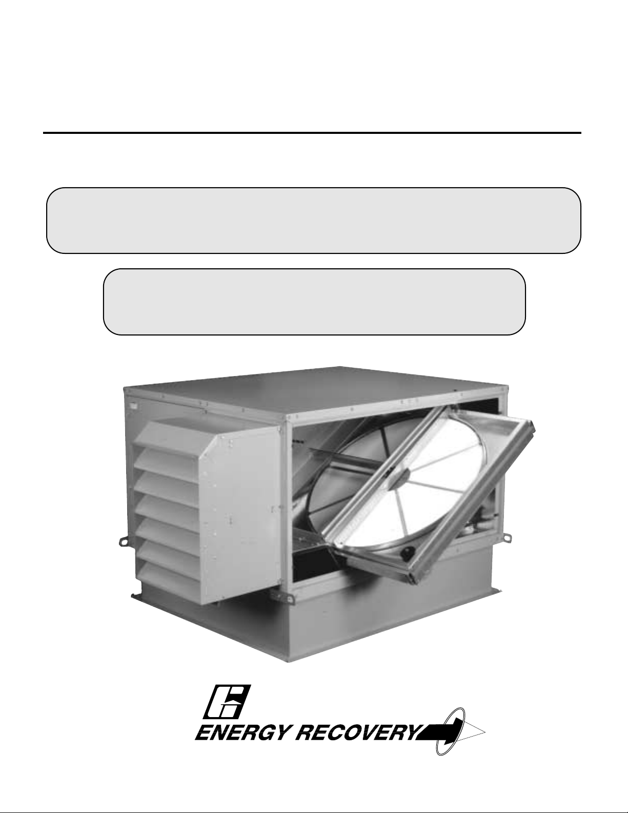
ENERGY RECOVERY VENTILATORS
Models ERV-251, 361, 521, 581, 522 & 582
INSTALLATION, OPERATION AND MAINTENANCE MANUAL
**WARNING**
DISCONNECT ALL ELECTRICAL POWER TO THE ERV PRIOR TO INSPECTION OR SERVICING BY
SECURING THE MAIN DISCONNECT SWITCH TO THE "OFF" POSITION. FAILURE TO COMPLY WITH THIS
SAFETY PRECAUTION COULD RESULT IN SERIOUS INJURY OR DEATH.
**IMPORTANT**
ALL FACTORY PROVIDED LIFTING LUGS MUST BE USED WHEN LIFTING ANY ERV.
FAILURE TO COMPLY WITH THIS SAFETY PRECAUTION COULD RESULT IN PROPERTY
DAMAGE, SERIOUS INJURY OR DEATH.
PART #455924
READ AND SAVE THESE INSTRUCTIONS
Page 2
GENERAL
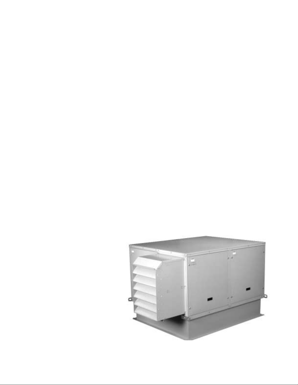
Greenheck Energy Recovery Ventilators, model ERV, are thoroughly inspected and test run at the factory.
However, damage may occur during shipping and handling. Consequently, it is important to inspect the unit for
visible and concealed damage before beginning installation. Report any damage to the shipper immediately. In
addition, assure all accessory items are present. Some accessory items are stored inside the unit during shipping.
Care must be taken during installation to prevent damage to units.
INSTALLATION
The system design and installation should
follow accepted industry practice, such as
described in the ASHRAE Handbook.
Minimum service clearance should be provided
on the side of the unit for routine service and
component removal should it become
necessary.
Before beginning installation see pages 8
through 11 for dimensional data and details on
appropriate service clearances.
Installation...............................................2
Lifting...................................................3
Mounting..............................................4
Duct Connection.................................6
Weatherhoods.....................................6
Electrical...........................................6-7
Dimensional Data
- 251, 361, 521, 581
......8
Service Clearances
- 251, 361, 521, 581
.....9
Dimensional Data
- 522, 582
.................10
Service Clearances
- 522, 582
...............11
System Startup .....................................12
Energy Wheel....................................12
Fan RPM............................................13
Fan Wheel .........................................13
Motors...............................................13
Setting for Options............................13
Routine Maintenance ..............................14
Belts ......................................................14
Fasteners and set screws....................14
Filters ....................................................15
Energy Recovery Wheel Maintenance ..16
Accessing the Energy Wheel ...............16
Removing Energy Wheel......................17
Cleaning Energy Wheel ........................17
Maintenance Documentation ............18-19
Troubleshooting.......................................20
Warranty ..................................................20
2
TABLE OF CONTENTS
Page 3
LIFTING
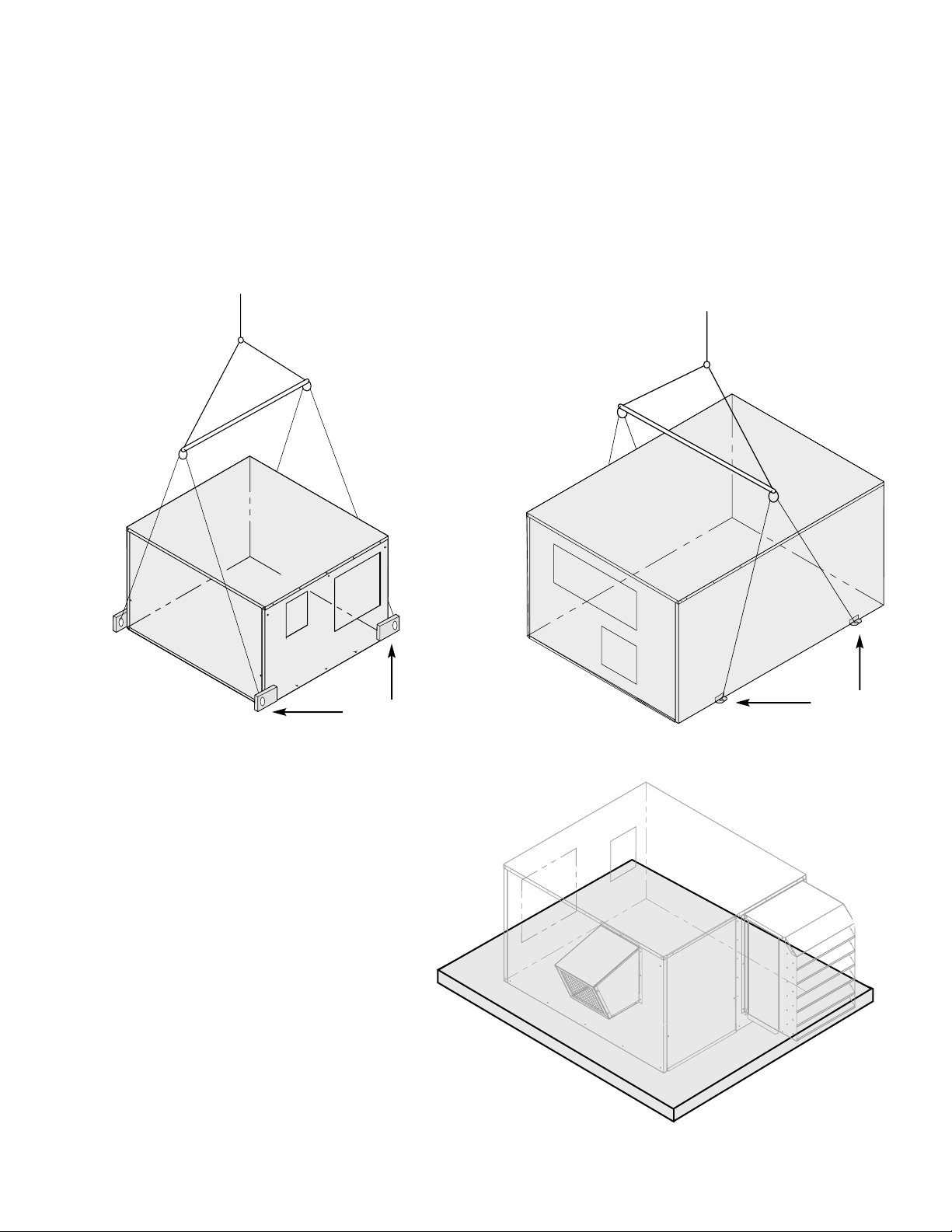
Greenheck model ERVs must be lifted as it ships from the factory. All units are equipped with lifting lugs.
THE USE OF ALL LIFTING LUGS IS MANDATORY WHEN LIFTING. Lifting of the ERV should only be
done with the access doors/panels closed and in place to avoid damage to the unit.
Use spreader bars to prevent damage to the unit cabinetry. Spreader bars must be positioned to prevent
the cables from rubbing against the unit frame or panels. Before hoisting into position, test lift the unit to
verify stability and balance. Avoid twisting or uneven lifting of the unit. Never lift an ERV by
weatherhoods.
FIGURE 2
ERV-522 and 582
FIGURE 1
3
SLAB MOUNTING
Arrangement D (Horizontal Discharge)
Slab Construction
• The recommended slab size is 12 inches
wider and longer than the total unit size.
• The material should be concrete with a
thickness of at least 4 inches and proper
reinforcement wire.
• The slab should be set and leveled on a
sufficient bed of gravel for proper drainage.
1. Slab Co
Recomme
total unit s
Recomme
ERV-251, 361, 521 and 581
Lift Lugs
Spreader Bar
Spreader Bar
Lift Lugs
Page 4
INSTALLATION (continued)
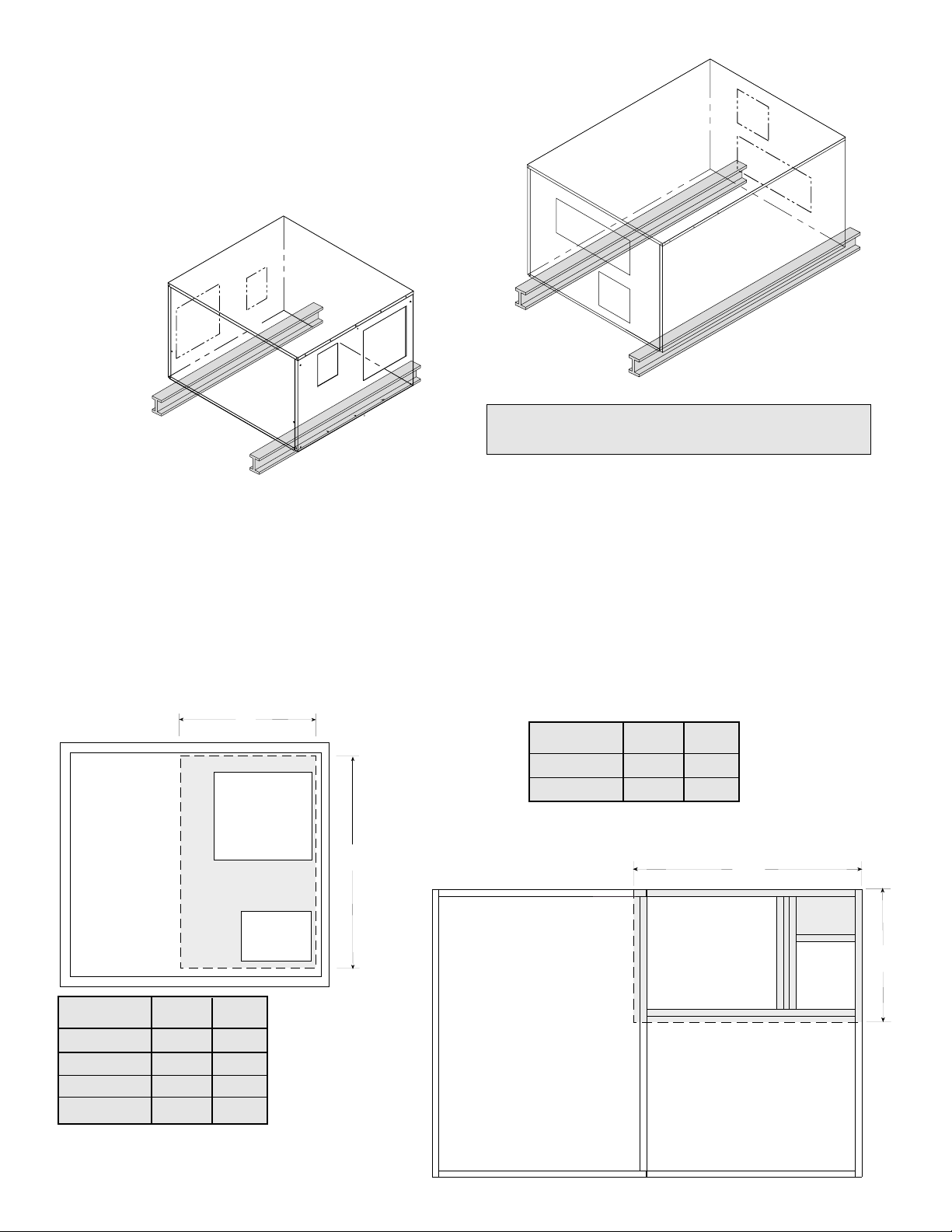
SURFACE RAIL MOUNTING
Arrangement A or D
For proper support, rails should be located 6 to 12 inches in
from the outer edges of the unit and should extend at least
6” beyond the sides of the unit. Rails are by others.
Front
Front
Back
Back
4
Refer to pages 8 through 11 for unit dimensions
and appropriate service clearances.
CURB MOUNTING
Arrangement B, C and D
Recommended Roof Opening
ERV-251, 361, 521 and 581
ERV-522 and 582
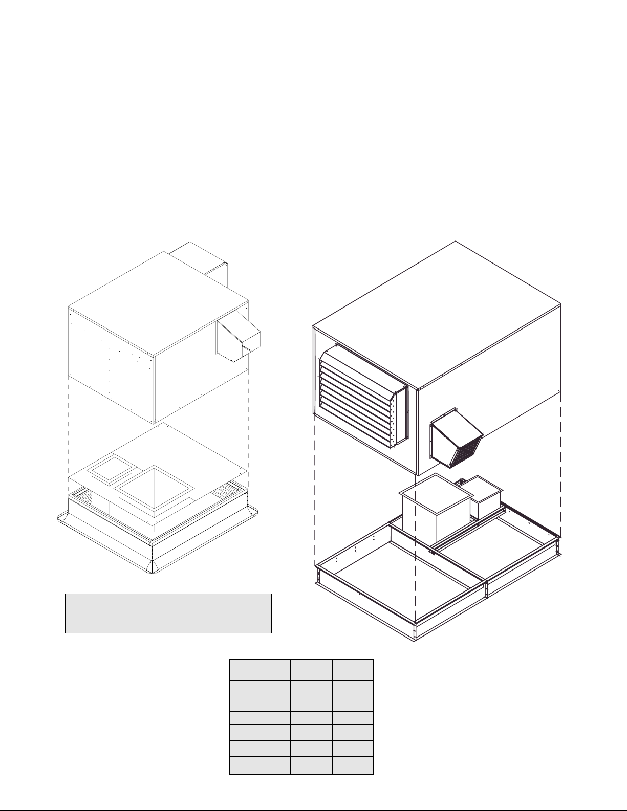
Roof curbs are Model GKD, which are shipped in a
knockdown kit and require field assembly (by others).
Assembly instructions are included with the curb.
2. Cut Roof Opening and Locate Curb
Locate the unit over the roof opening, so the unit
openings and corresponding ducts line up. See the
drawing below.
Be sure to allow for the recommended service clearances.
Keep the inlet of the ERV away from any other exhaust
fans. See page 6 for Recommended Duct Sizes.
EXHAUST
INLET
SUPPLY
OUTLET
V
U
Recommended Roof Opening
ERV-522 and 582
Model U V
ERV-251 26.5 20
ERV-361 43 26
ERV-521 58 35
ERV-581 60 30
Model U V
ERV-522 65 37
ERV-582 77 38
ERV-251, 361, 521 and 581
1. Factory Supplied Roof Curbs
Roof curbs are either Model GPNS or GPI, which are
factory fabricated and assembled.
U
V
EXHAUST
INLET
SUPPLY
OUTLET
All dimensions shown are in inches.
Page 5
Model L W
ERV-251 30.5 42.5
ERV-361 58.5 47.5
ERV-521 63.5 63.5
ERV-581 71.8 66
ERV-522 120.5 80.5
ERV-582 142.25 93
Roof curb details, including duct
location dimensions, are available on
ERV roof curb submittals.
FIGURE 3
FIGURE 4
5
3. Install Curb
Locate curb over roof opening with dimensions
shown on page 4 and fasten in place.
Check that the diagonal dimensions are within
±1/8” of each other and adjust as necessary.
Shim as required to level.
Lower unit onto curb by following the LIFTING
instructions on page 3 of this manual. Note, roof
curbs fit inside the ERV unit base.
4. Install Duct Work
Installation of all ducts should be done in
accordance with SMACNA and AMCA guidelines.
The chart on page 6 shows the duct sizes and
straight lengths recommended for optimal
performance (AMCA 201-90). Using duct sizes
less than the recommended lengths will affect fan
performance. Good duct installation practices
should be followed for the remaining ductwork.
ERV-251, 361, 521 and 581
The duct adapter should be used only for properly
locating ducts on these units. The factory duct
adapter must not be used for structural support of
the ducts.
ERV-522 and 582
This duct adapter can be used to locate and
support the duct work.
Curb Outside Dimensions
L
W
W
L
ERV-522 and 582
ERV-251, 361, 521 and 581
All dimensions shown are in inches.
Page 6
Main
Disconnect
On
Off
Exhaust
Hood
Control Center
Exhaust Hood
Supply Hood
Main
Disconnect
On
Off
Control Center
Main
Disconnect
On
Off
ERV-251 & 581
ERV-361 & 521
ERV-522 & 582
FIGURE 3
WEATHERHOODS (Arrangement B, C and D)
The outdoor air intake weatherhood is shipped factory assembled and mounted to the ERV. The exhaust
discharge weatherhood is fastened to the skid and shipped with the ERV unit.
DUCT WORK CONNECTIONS
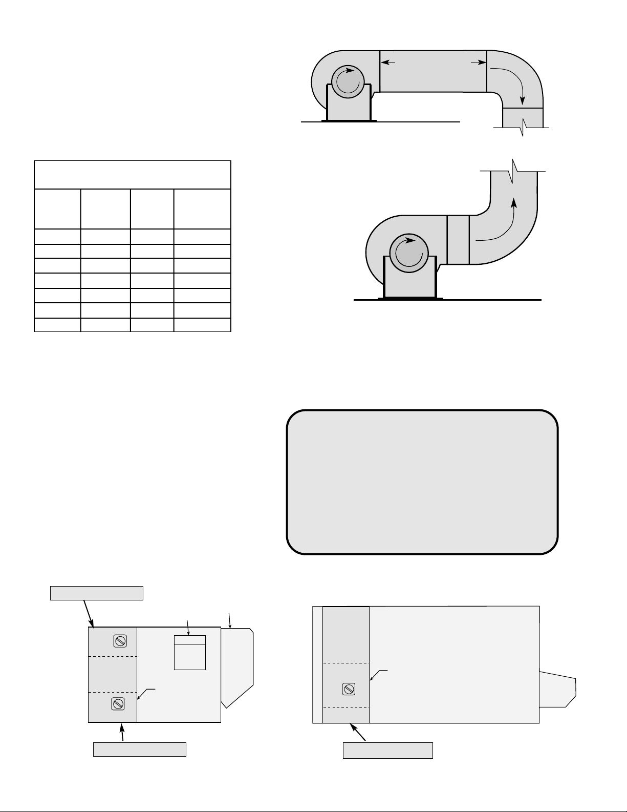
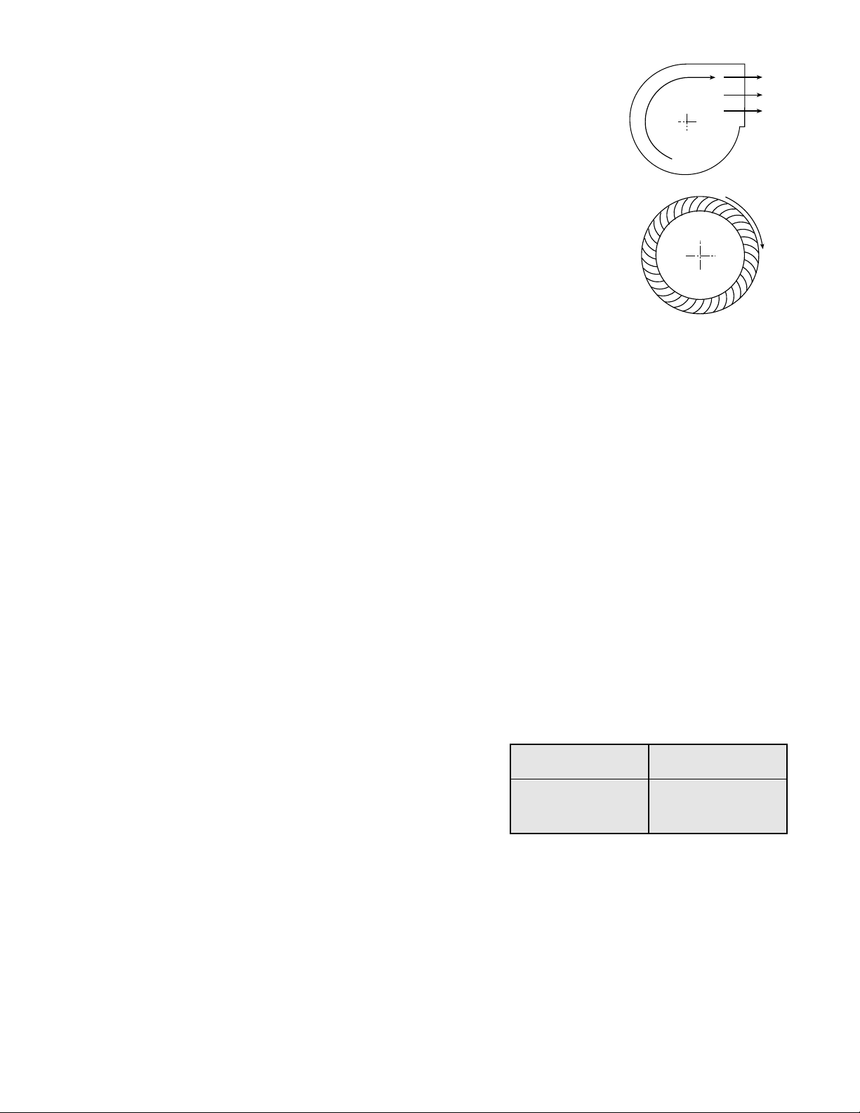
Examples of good and poor fan-to-duct
connections are shown in Figure 3. Air flow
out of the fan should be directed straight or
curve the same direction as the fan wheel
rotates. Poor duct installation will result in low
airflow, increased noise levels and other
system effects.
INSTALLATION (continued)
6
Recommended Discharge
Duct Size and Length
ERV
ERV
Duct
Straight
Model
Blower
Size
Duct
Size Length
251 10 9 x 9 40
361 10 14 x 14 40
521 12 20 x 20 48
581 15 28 x 28 60
522S 15 28 x 28 60
522H 18 32 x 32 72
582 20 34 x 34 80
ELECTRICAL CONNECTIONS
CAUTION !
If any of the original wire must be replaced,
the replacement wire must have a temperature
rating of at least 105°C, except for energy cut-off
or sensor lead wire which must be 150°C.
DANGER !
High voltage electrical input is required for this
equipment. This work should be performed by a
qualified electrician.
Before connecting power to the unit, read and
understand the following instructions and
wiring diagrams. Complete wiring diagrams are
attached inside the door(s) of the unit.
All wiring should be done in accordance with
the National Electrical Code ANSI/NFPA 70latest edition and any local codes that may
apply. In Canada, wiring should be done in
accordance with the Canadian Electrical Code.
The equipment must be properly grounded.
FIGURE 4
All dimensions shown are in inches.
n
o
i
t
a
t
o
R
Length of Straight Duct
GOOD
n
o
i
t
a
t
o
R
POOR
Page 7
1
2
3
4
6
5
7
8
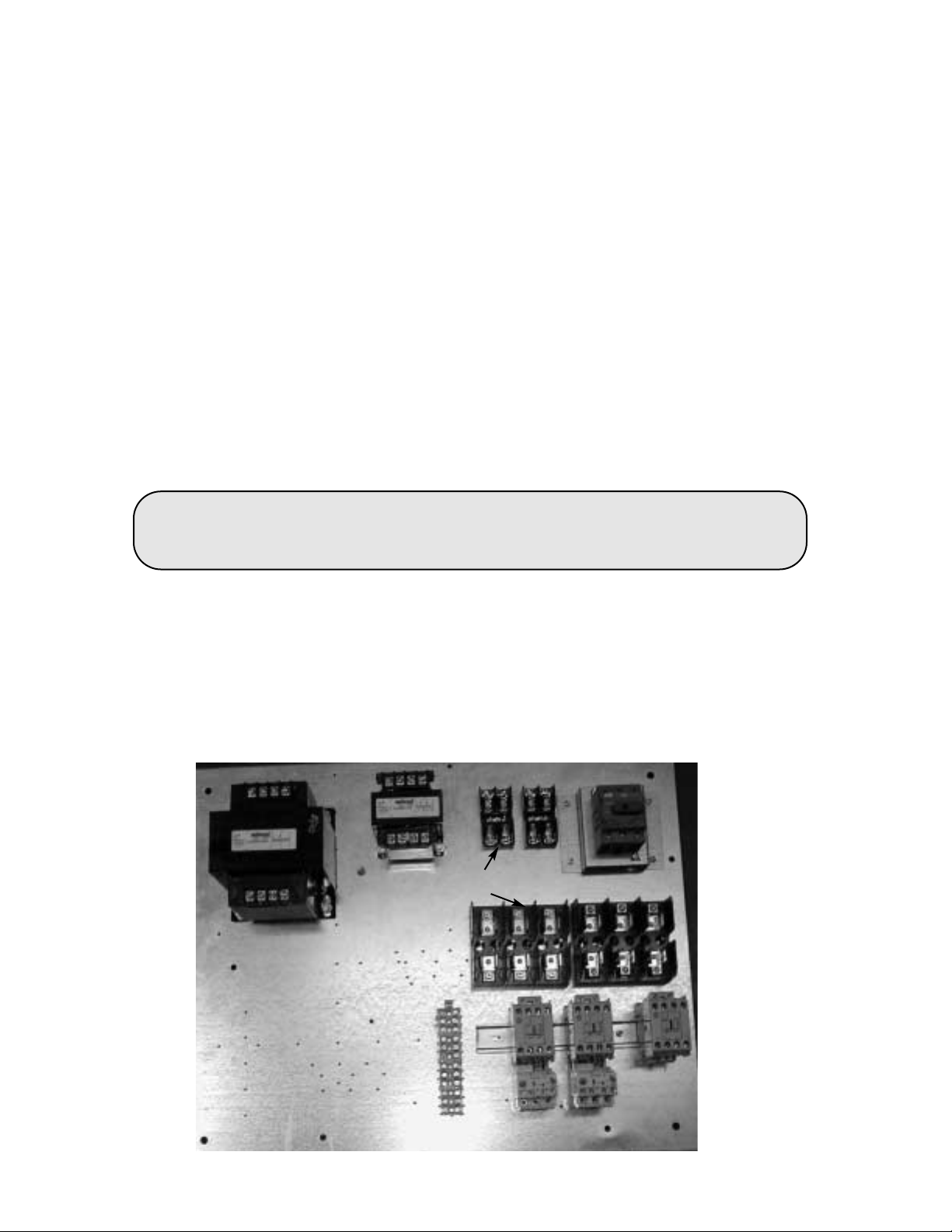
Sequence for wiring ERV unit:
1.The unit’s nameplate states the voltage and total amperage required. The wire
supplying power to the unit should be sized for the label’s voltage and amperage.
2.The main power line should be connected to the disconnect switch. Make sure that the
disconnect lugs are securely tightened. A door interlocking safety disconnect is provided
as a standard feature with model ERV, (see Figure 4, page 6).
Power may be routed to the control center through the curb or the knock-outs on the side
of the ERV. The locations for the knockouts and control center are provided on the ERV
submittal. If power will be routed through the curb and unit base panels, then run the
power supply up through the base panel near the exhaust intake opening of the ERV.
3.Connect control wiring to the terminal strip located in the electrical control center. All
ERV units include, as standard, a transformer to achieve the 24 VAC control voltage.
4.Refer to the wiring diagram located in the control center or included with this manual for
controlling the ERV.
CAUTION
Any wiring deviations may result in personal injury or property damage. Greenheck is not
responsible for any damage to, or failure of the ERV unit caused by incorrect field wiring.
7
INSTALLATION (continued)
1. Main Disconnect
2. Motor Starter -Exhaust Air Fan
3. Motor Starter-Outdoor Air Fan
4. Motor Contactor-Energy Wheel
5. Control Power Transformer
(460 to 24 VAC)
6. Energy Wheel Motor Transformer
(460 to 230 VAC)
7. 24 VAC Terminal strip
8. Internal fuses for the control
circuit and wheel drive transformer
ELECTRICAL CONNECTIONS
TYPICAL CONTROL CENTER COMPONENTS
Page 8
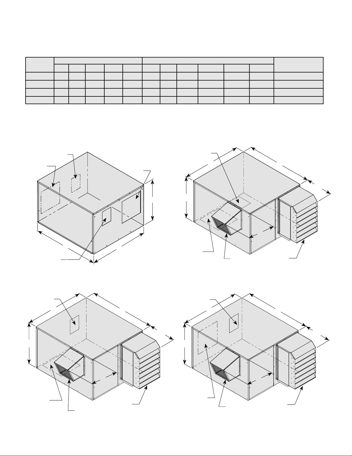
Exterior Dimensions Duct Dimensions * Approximate
Model
ABCD E FG K L Q P
Weight (lbs)
ERV-251 46 34 27 16 8 10 16 63/4
7 10 16 250
ERV-361 62 51 34 15 15 18 18 8
3
/8 111/2 19 18 750
ERV-521 67 67 44 18 15 24 24 103/4 131/2 26 26 1200
ERV-581 75 70 67 16 22 22 27 16 183/4 28 48 1450
MODELS ERV-251, ERV-361, ERV-521 AND ERV-581
Arrangement A
A
B
C
Outdoor Air Inlet
Q x P
Exhaust Air Discharge
LxK
Outdoor Air Discharge
LxK
Exhaust Air Inlet
FxG
C
B
A
D
E
Arrangement B
Exhaust Air Inlet
FxG
Outdoor Air Discharge
LxK
Intake Hood
Exhaust Hood
C
B
A
D
E
Arrangement C
Exhaust Hood
Intake Hood
Exhaust Air Inlet
FxG
Outdoor Air Discharge
LxK
Exhaust Air Inlet
FxG
Outdoor Air Discharge
LxK
Intake Hood
C
B
A
D
E
Arrangement D
Exhaust Hood
All dimensions shown are in inches.
DIMENSIONAL DATA
8
* Weight dependent on components and accessories.
Page 9
Supply Hood
Exhaust
Hood
Cassette Slides out
Access Panels
Access Panel
Access Panel
Exhaust
Side
Supply
Side
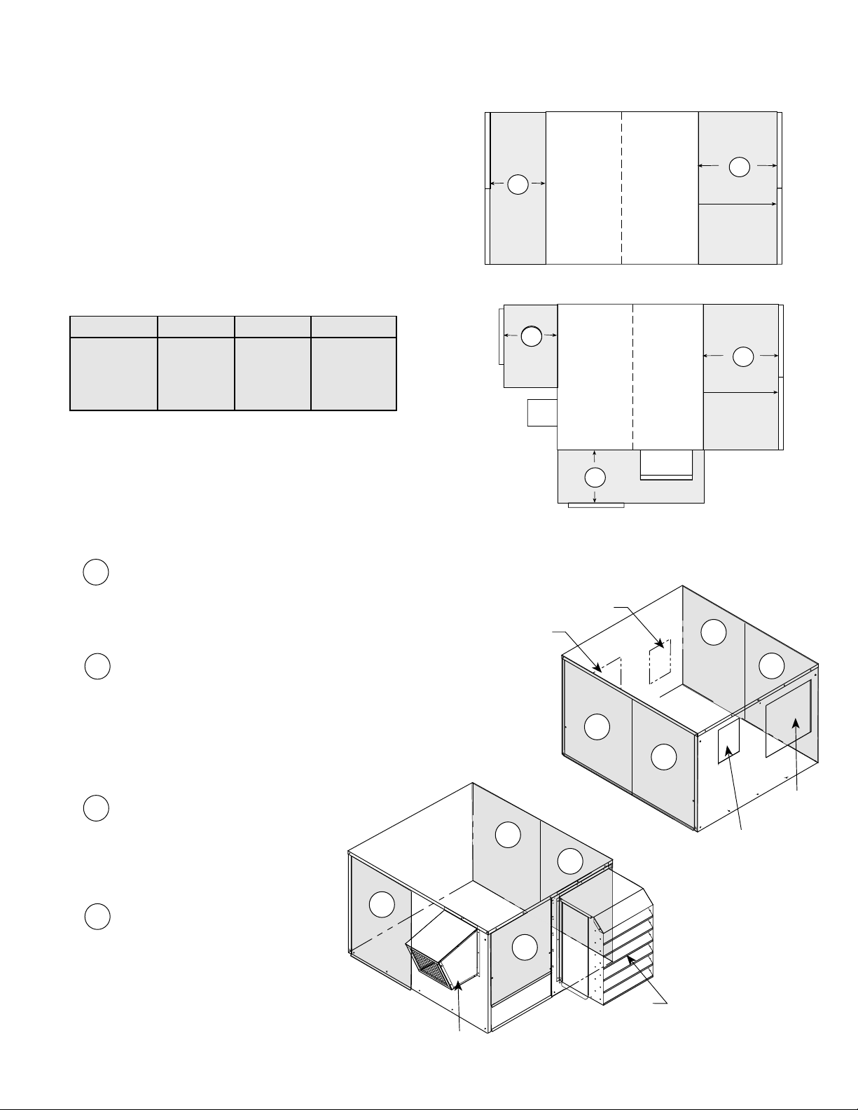
SERVICE CLEARANCES FOR ERV-251, 361, 521 AND 581
ACCESS PANEL LOCATIONS
ERV units require minimum clearances to perform
routine maintenance, such as filter replacement, energy
wheel cassette inspection, and fan belt adjustment.
Blower and motor assemblies, energy recovery wheel
cassette and filter sections are always provided with a
service door or panel for proper component access.
Clearances for component removal are shown below.
Outdoor Air
Inlet
Exhaust Air
Discharge
Exhaust Air
Inlet
Outdoor Air
Discharge
Model R S T
251 32 30 30
361 44 30 30
521 60 40 40
581 65 40 40
ERV-251, 361, 521 and 581 Recommend Clearances
All dimensions shown are in inches.
9
1
1
4
3
4
2
2
3
Exhaust
Hood
Intake
Hood
4
1
2
3
Access panel for:
•Outdoor air blower and motor
•Energy wheel cassette
Access panel for:
•Energy wheel cassette
•Internal Filters
•Outdoor air inlet damper
•Frost control
•Outdoor air sensors
Access panel for:
•Main disconnect
•Electrical control center
•Internal filters
Access panel for:
•Exhaust air blower and motor
Arrangement A
Arrangement A
Arrangement B, C or D
Arrangement B, C or D
T
T
T
R
R
S
Access Panels
Exhaust
Side
Supply
Side
Cassette Slides out
Access Panels
Page 10
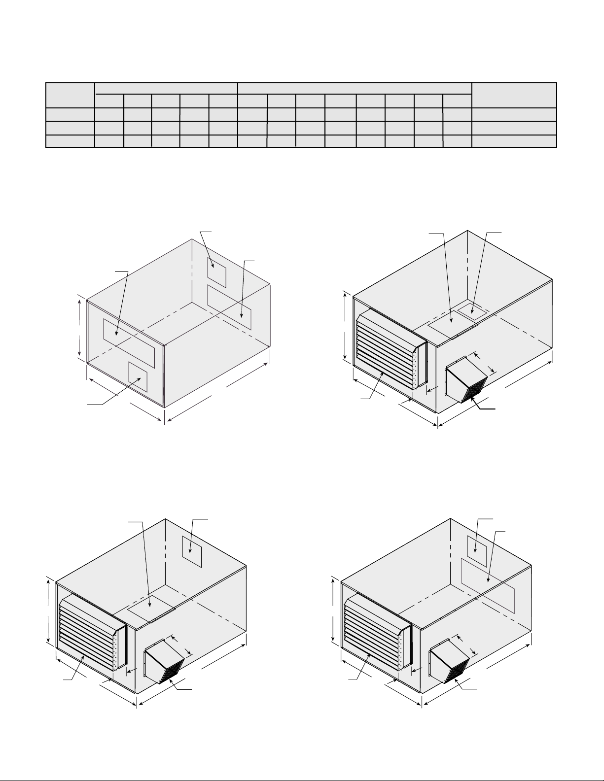
DIMENSIONAL DATA
10
Outdoor Air Discharge
L x K
Exhaust Air Inlet
H x J
Exhaust Air Discharge
L x K
Outdoor Air Inlet
Q x P
C
B
A
C
B
D
A
E
Outdoor Air Discharge
L x K
Exhaust Air Inlet
H x J
Exhaust
Hood
Intake
Hood
C
B
D
A
E
Outdoor Air Discharge
L x K
Exhaust Air Inlet
H x J
Exhaust
Hood
Intake
Hood
C
B
D
A
E
Outdoor Air Discharge
L x K
Exhaust Air Inlet
H x J
Exhaust
Hood
Intake
Hood
Arrangement A
Arrangement B
Arrangement D
Arrangement C
* Weight dependent on components and accessories.
All dimensions shown are in inches.
ABCDEFGHJKLQP
ERV-522S 124 84 64 16 19 26 36 48 25 16 18 5/
8 60 25 3000
ERV-522H 124 84 64 16 19 26 36 48 25 19 22 60 25 3000
MODEL ERV-522 AND ERV-582
Model
Exterior Dimensions Duct Dimensions
* Approximate
Weight
ERV-582H
146
97
77
26
3
/4
31
38
60
28
25
25
70
30
3600
17
1
/2
Page 11
Model X
ERV-522 38
ERV-582 56
Cassette
Cassette
Supply
Weather Hood
Exhaust
Weather Hood
Access Panel
Access PanelAccess Panel
Access Panel
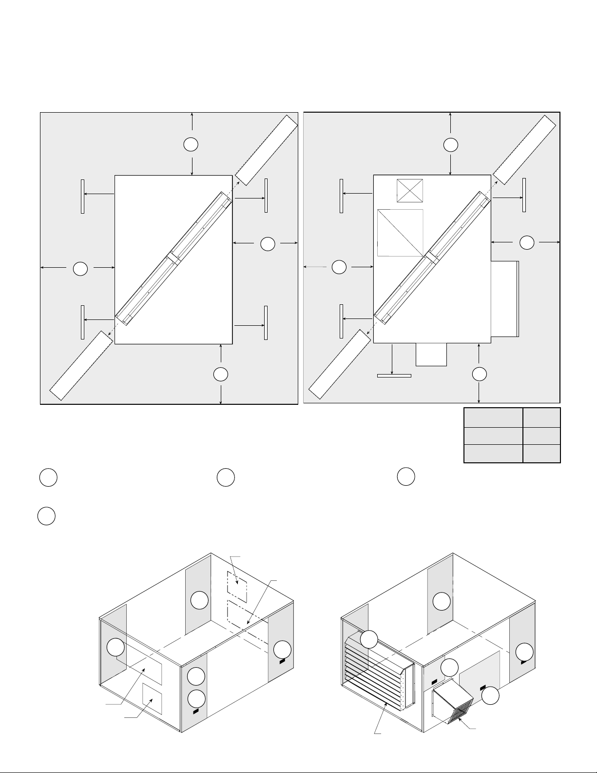
SERVICE CLEARANCES FOR ERV-522 AND 582
ACCESS PANEL LOCATIONS
ERV units require minimum clearances to perform routine maintenance, such as filter replacement, energy
wheel cassette inspection, and fan belt adjustment. Blower and motor assemblies, energy recovery wheel
cassette and filter sections are always provided with a service door or panel for proper component access.
Clearances for component removal are shown below.
Interior
Rooftop
Exhaust Air
Inlet
Outdoor Air Inlet
Exhaust Air Discharge
Exhaust Hood
Intake Hood
Outdoor Air
Discharge
C
asse
tte
C
asse
tte
Access PanelAccess Panel
Access Panel
Access Panel
All dimensions shown are in inches.
11
2
1
3
Access panel for:
•Electrical Control Center
•Main disconnect
•Supply blower and motor
•Exhaust inlet damper
Access panel for:
•Energy wheel cassette
•Internal filters
•Frost control
•Outdoor air sensor
4
Access panel for:
•Preheater controls
•Supply inlet damper
Access panel for:
•Exhaust blower and motor
3
3
3
3
1
4
4
1
2
2
Arrangement A Arrangement B, C or D
X
X
X
X
X
X
X
X
Page 12
For proper unit function and safety, follow everything in this startup procedure in the order presented. This is to
be done after the electrical connections are complete.
Special Tools Required • Volt meter
• Incline manometer or equivalent
• Tachometer
• Amperage meter
1. General
Check all fasteners and set screws for tightness. This is especially important for bearings and fan wheels.
Also, if dampers are not motorized, check that they open and close without binding.
SYSTEM STARTUP
**WARNING**
DO NOT OPERATE ENERGY RECOVERY VENTILATOR WITHOUT THE FILTERS AND BIRDSCREENS INSTALLED.
THEY PREVENT THE ENTRY OF FOREIGN OBJECTS SUCH AS LEAVES, BIRDS, ETC.
DO NOT REMOVE ACCESS PANELS OR OTHER COMPONENTS WHILE STANDING ON A LADDER OR OTHER
UNSTEADY BASE. ACCESS PANELS AND COMPONENTS ARE HEAVY AND SERIOUS INJURY MAY OCCUR.
12
2. Check Voltage
Before starting the unit compare the supplied voltage with the unit’s nameplate voltage and the motor
voltage.
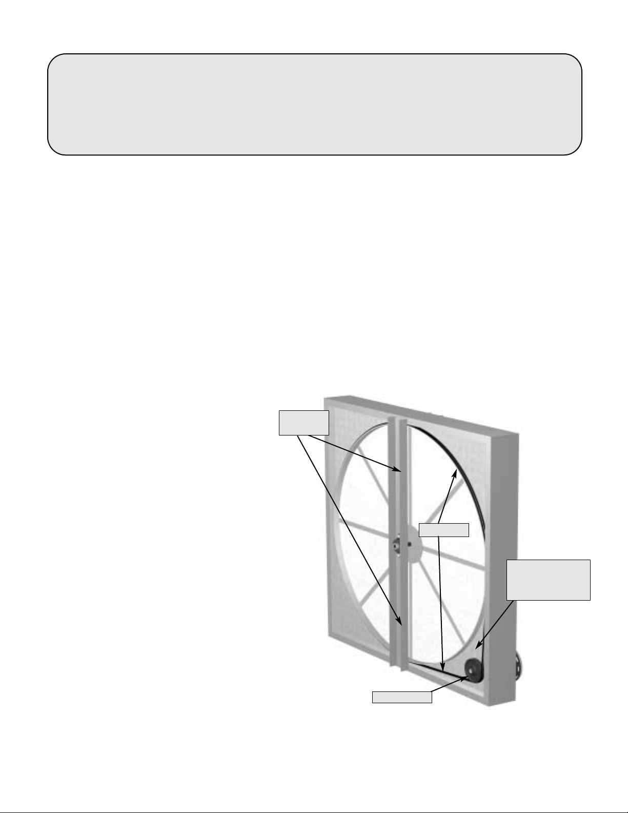
3. Energy Recovery Wheel
First, follow the instructions on page 16 for
pulling the energy recovery cassette halfway
out of the unit.
DRIVE BELT
Turn the energy recovery wheel by hand to verify
free operation. Inspect the belt, which drives the
energy wheel rotation. Make sure the belt rides
smoothly through the pulley and over the wheel
rim.
AIR SEALS
Turn the energy recovery wheel by hand to verify
free operation. Check that the air seals, located
around the outside of the wheel and across the
center (both sides of wheel), are secure and in
good condition.
Air seals which are too tight will prevent proper
rotation of the energy recovery wheel. Recheck
the air seals for tightness. Air seal clearance may
be checked by placing a sheet of paper, like a
feeler gauge, against the wheel face. To adjust the
air seals, loosen all eight seal retaining screws.
These screws are located on the bearing support
that spans the length of the cassette through the
wheel center. Tighten the screws so the air seals tug slightly on the sheet of paper as the wheel is turned.
Replace cassette into unit, plug in wheel drive, replace access door and apply power. Observe that the
wheel rotates freely. If wheel does not rotate or is binding, remove the cassette (instruction on page 16).
FIGURE 5
Drive Belt
Drive Pulley
Adjustable
Air Seals
Label showing
cassette serial no.
and date code
Page 13
7. Settings for Optional Components
Frost Control
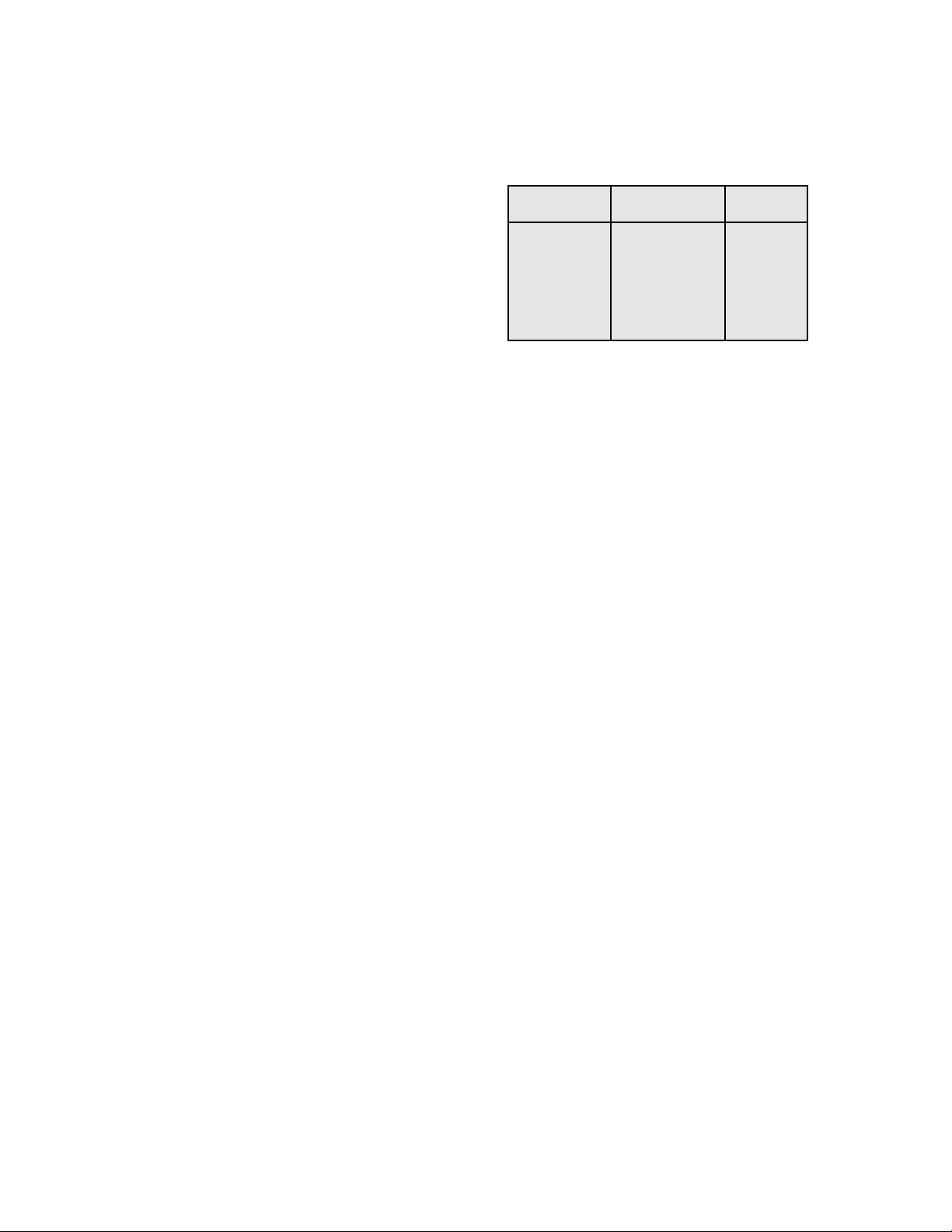
Preheater: If outdoor air temperature is below set point then the preheater heats incoming outdoor air above
the Frost Threshold temperature. Typical settings are shown at the right.
Timed Exhaust: De-energizes the outdoor air blower for a
specified period, if the outdoor temperature is below the set
point. The outdoor air blower returns to normal operation for a
specified period. This cycle ends when the outside
temperature rises above the set point.
Typical settings are: Temp. Sensor : 0°F,
Timer (Blower Off): 5 minutes and Timer (Blower On) 45 minutes.
Outdoor/Economizer Sensors
All economizer sensors must be by-passed for proper winter or heating season operation. The by-pass can
be accomplished utilizing the Auto-override option or by wiring a summer/winter switch as shown on the ERV
wiring or ladder diagram.
Temperature Sensor: De-energizes the energy wheel drive motor when the outdoor temperature is below
the set point. The wheel motor re-energizes when the outdoor air temperature is above the set point.
Typical settings are: 65°F
Enthalpy Sensor: De-energizes the energy wheel drive motor when the outdoor enthalpy drops below the
set point. The wheel motor re-energizes when the outdoor air enthalpy is above the set point.
Four settings available on controller.
13
4. Check Blower Rotation
First, hand rotate the blower to ensure that the wheel is not rubbing against the
scroll. If the blower is rotating in the wrong direction, the unit will move some air
but not perform properly.
To check the rotation, open the blower access panels, which are labeled either
supply or exhaust, and run the blower momentarily to determine the
rotation.
To reverse the rotation, turn the power off and use the following procedure:
• For single phase units, rewire the motor per the instructions on the motor.
• For three phase units, interchange any two power leads.
This can be done at the motor starter.
5. Air Volume Check and Measurement
Along with the building balance, the units air volume (cfm) should be measured and
compared with its rated air volume. This unit is flexible (fixed drives for 15 hp units)
for varying air volume, but the actual air volume should be known for making final adjustments.
Note: Model ERV-251 is direct drive, balancing damper or speed control needed for air flow balancing.
The most accurate way to measure the air volume is by using the pitot traverse method in the ductwork away
from the blower. Other methods can be used but should be proven and accurate.
To adjust the air volume, change the fan rpm or the system losses. See Trouble Shooting section on page 20.
6. Measure Motor Voltage, Amperage and Fan RPM
All access doors must be installed except the control center door (Exception: ERV-522 control center door
must be installed). Measure and record the input voltage and motor amperage(s).
To measure the fan rpm, the blower door will need to be removed. Minimize measurement time because the
motor may overamp with the door removed. Do not operate units with access doors/panels open as the
motors will overload.
With blower door closed compare measured amps to the motor nameplate full load amps and correct if
overamping.
FROST THRESHOLD TEMPERATURE
Indoor RH at Frost Threshold
70° F Temperature
20% -10°F
30% -5°F
40% 0°F
n
o
i
t
a
t
o
R
t
a
i
t
o
o
n
R
Airflow
Page 14
ROUTINE MAINTENANCE
CAUTION: See **WARNING** on Page 1
After the ERV has been put into operation, an annual inspection and maintenance
program should be set-up to preserve reliability and performance. Include the
following items in this program,
• BELTS • REMOVAL OF DUST/DIRT
• FASTENERS • FILTER MAINTENANCE
• SET SCREWS • ENERGY WHEEL CASSETTE
BELTS
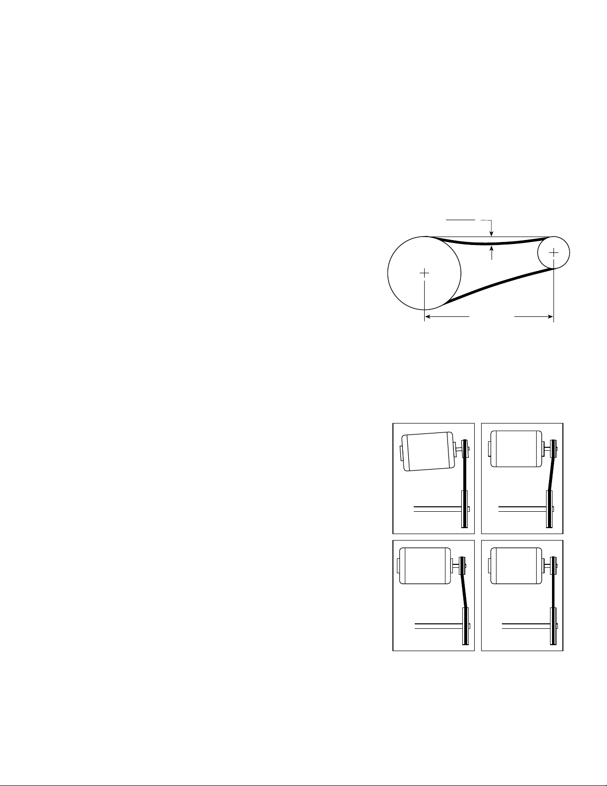
Premature belt failures are frequently caused by improper belt tension
(either too tight or too loose) or misaligned pulleys. The proper tension
for operating a V-belt is the lowest tension at which the belts will not
slip at peak load conditions. For initial tensioning, the proper belt
deflection half way between pulley centers is
3
/8
inch
per foot of belt
span. The belt deflection should be
3
/8
inch using moderate thumb
pressure at midpoint of the drive (See Figure 6).
Check belt tension two weeks after start-up and periodically thereafter.
To adjust belt tension, simply loosen four fasteners (two on each side
of the motor plate) and slide the motor plate away from the fan shaft
until proper belt tension is attained. On some ERVs, fasteners attaching
the motor to the motor plate must be loosened in order to adjust the
belt.
It is very important that the drive pulleys remain in proper alignment
after adjustments are made. Misalignment of pulleys will result in
premature belt wear, noise, vibration and power loss.(See Figure 7).
Maintain belts and motors through the provided access panels.
FASTENERS AND SET SCREWS
Any fan vibration has a tendency to loosen mechanical fasteners. A
periodic inspection should include checking all fasteners and set
screws for tightness. Particular attention should be paid to set screws
attaching the fan wheel to the shaft and the shaft to the bearings.
Loose bearing set screws will lead to premature failure of the fan shaft.
REMOVAL OF DUST AND DIRT
Dirt clogs cooling openings on the motor housing, contaminates
bearing lubricant and collects on fan wheel blades causing severe
imbalance if left unchecked. The exterior surface of the motor, inlet area
and entire fan wheel should be thoroughly cleaned periodically. Use
caution and do not allow water or solvents to enter the motor or
bearings. Under no circumstances should motors or bearings be
sprayed with steam or water. Maintenance to these components is
achieved through the provided access panels.
14
FIGURE 6
FIGURE 7
Deflection =
Belt Span
64
Belt Span
WRONG WRONG
WRONG CORRECT
Page 15
Model Filter Size Quantity
ERV-251 16 x 25 1
ERV-361 16 x 20 2
ERV-521 16 x 25 3
ERV-581 16 x 20 6
ERV-522 16 x 25 7
ERV-582 20 x 25 6
EXTERNAL FILTER MAINTENANCE
Aluminum mesh 2 inch filters are located in
the supply weatherhood on outdoor units.
Filters should be checked and cleaned on a
regular basis for best efficiency. The
frequency of cleaning depends upon the
cleanliness of the incoming air.
To remove these filters, pull the side access
panel off and simply slide the filters out of the
weatherhood.
Clean filters by rinsing with a mild detergent in
warm water. After the filters are dry, an
adhesive spray available at most filter
distributors may be applied to increase filter
efficiency.
15
Internal
INTERNAL FILTER MAINTENANCE
Opening the access panels labeled "Filter
Access" provides access to the 2 inch deep,
pleated 30% efficient filters. These filters
should be checked regularly and cleaned or
replaced as needed.
Page 16
CAUTION: See **WARNING** on Page 1
Annual inspection of the energy recovery wheel is recommended. ERV units ventilating smoking lounges and
other non-clean air spaces should have energy recovery wheel inspections more often based upon need.
FIGURE 8
16
MAINTENANCE OF THE ENERGY RECOVERY WHEEL
FIGURE 10
ACCESSING ENERGY RECOVERY WHEEL
IN MODELS ERV-251, 361, 521 and 581
Disconnect power to the ERV. Remove access
panel(s) labeled “Energy Wheel Cassette Access”.
UNPLUG the wheel drive motor. The center channel
must be removed to access the energy wheel
cassette. Use a 5/16 inch open or close wrench to
remove the (3) fasteners that hold the center channel
in place.
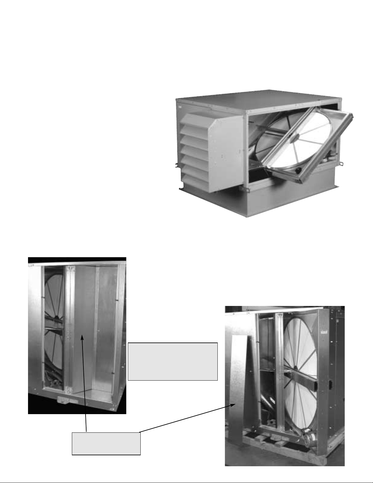
Pull the cassette halfway out as shown in Figure 8.
When service is complete, reattach the center
channel before putting access panels back in place.
ACCESSING ENERGY RECOVERY WHEELS
IN MODEL ERV-522 AND 582
Disconnect power to the ERV. Remove access panels labeled
“Energy Wheel Cassette Access”, which reveals the energy
wheel cassette. There are additional panels that must be
removed in order to slide out the cassettes. Figure 9 shows
the energy wheel and panel.
UNPLUG the wheel drive motor and pull the cassette halfway
out as shown in Figure 10.
This panel must be
removed before energy
wheel can slide out.
NOTE: ERV model’s 522 and
582 each have two energy
wheels with access panels for
both wheels. Wheels slide out
at opposite corners.
FIGURE 9
Page 17
ERV-251
First, remove the drive belts and the
collars on both bearings. On the pulley
side of the cassette remove the (4)
fasteners that hold the bearing support
channel in place. Once the bearing
support is removed the wheel can be
pulled from the cassette. To replace
the wheel reverse this procedure.
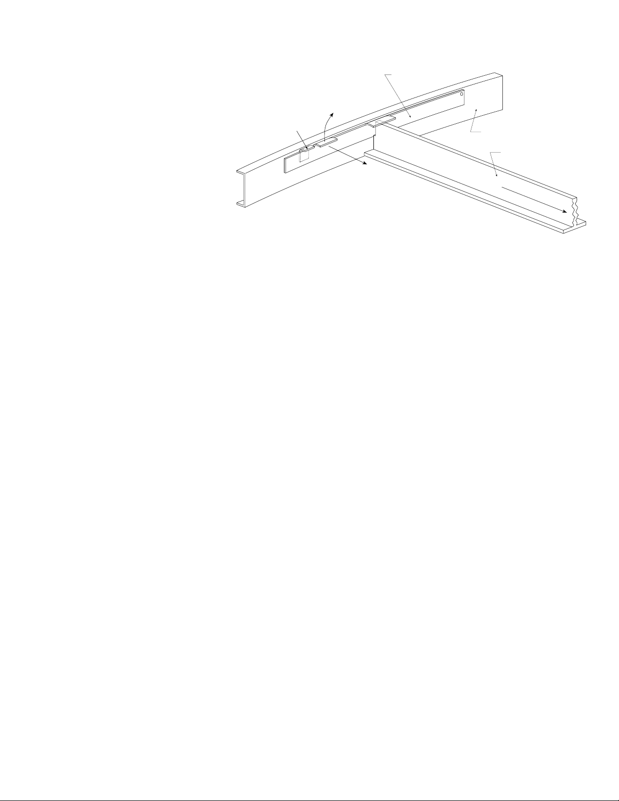
ERV-361, 521, 581, 522 & 582
(stainless steel rim)
Steel retainers are located on the inside
of the wheel rim (see Figure 11). Push
the retainer towards the center of the
wheel, then lift up and away to release
segments.
17
NOTE: PLACE RETAINERS BACK IN THE ORIGINAL
POSITION BEFORE ROTATING THE ENERGY
RECOVERY WHEEL. OTHERWISE DAMAGE
TO THE RETAINER WILL OCCUR.
REMOVING THE ENERGY RECOVERY WHEEL OR SEGMENTS
FIGURE 11
RECOMMENDED CLEANING PROCEDURE FOR ENERGY RECOVERY WHEELS
First, remove the energy recovery wheel segments by following the instructions on this page. (For one-piece
wheels smaller than 30 inches in diameter, remove the wheel from the cassette.)
Wash the segments or small wheels with a non-acid based (evaporator) coil cleaner or alkaline detergent
solution. Non-acid based coil cleaner such as KMP Acti-Clean AK-1 concentrate in a 5% solution has been
demonstrated to provide excellent results. Do not use acid based cleaners, aromatic solvents,
temperatures in excess of 140°F or steam; damage to the wheel may result. Soak in the cleaning
solution until grease and/or tar deposits are loosened. Internal heat exchange surfaces may be examined by
separating the polymer strips by hand. (Note: some staining of the desiccant may remain and is not harmful
to performance.)
After soaking, rinse the dirty solution from the wheel until the water runs clear. Allow excess water to drain
prior to replacing segments in the wheel or reinstalling the wheel in the cassette. A small amount of water
remaining in the wheel will be dried out by the airflow.
FREQUENCY OF ENERGY WHEEL CLEANING
A regular cleaning cycle must be established for the energy recovery wheel in order to maintain optimum
sensible and latent energy transfer. In reasonably clean environments such as schools, offices or retail stores,
the energy recovery wheel should be inspected annually and cleaned as needed.
For applications experiencing unusually high levels of tobacco smoke, such as lounges, nightclubs, bars and
restaurants, washing of the energy recovery wheel every six months may be necessary to maintain latent
energy (water vapor) transfer efficiency.
Failure to follow a regular cleaning cycle for the energy recovery wheel can result in significant energy transfer
performance losses.
Bracket Segment Retainer
CatchSegment Retainer
Lift Away
From Segment
Inside of Wheel Rim
Spoke
Push Toward Center
Center of W
heel
Page 18
18
ENERGY RECOVERY WHEEL DRIVE BELT
Drive belt(s) should be inspected annually. Normal operation eventually causes stretching or wear
on the belt(s). Once this occurs the belt(s) should be replaced.
Replacement or spare energy wheel drive belt kits are available and ship with their own instructions.
The serial number and date code of the energy wheel cassette are required to obtain the proper
replacement belt kit from the factory.
MAINTENANCE OF THE ENERGY RECOVERY WHEEL (continued)
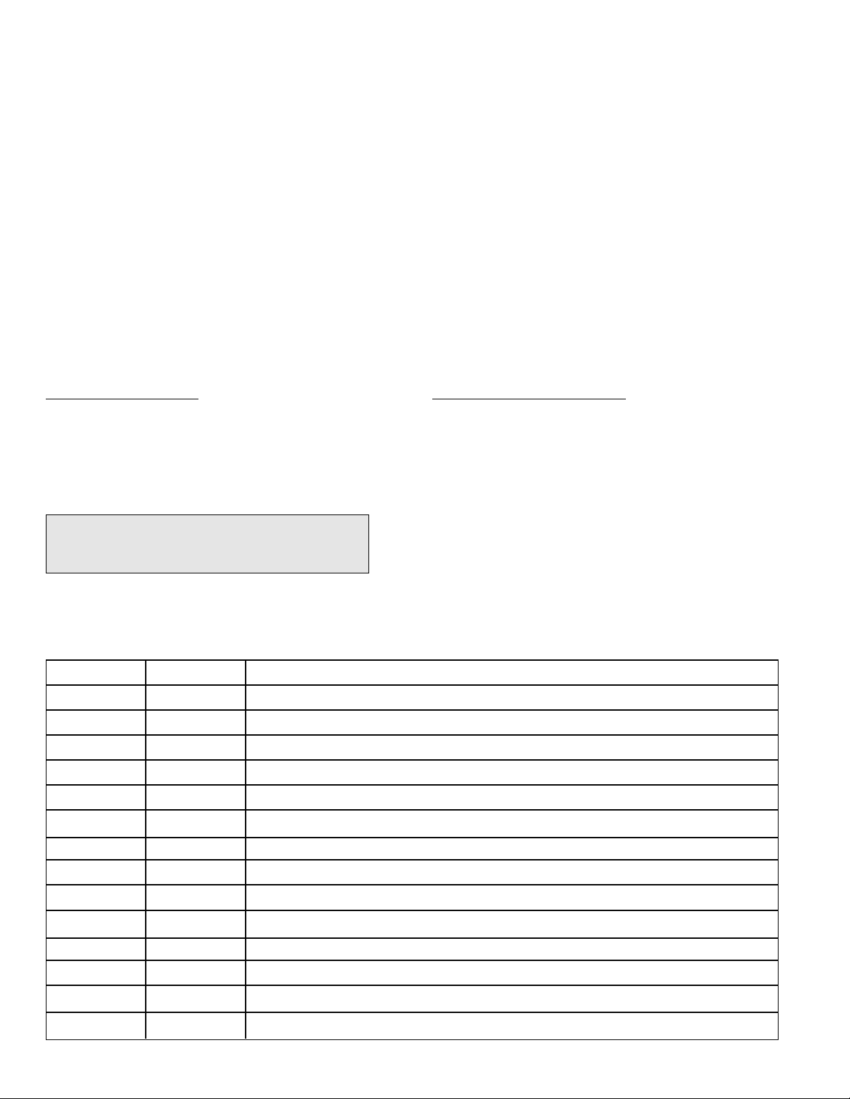
Name Plate Information
Model: _______________________________
Volts: ___________Hertz: _______ Phase: ___
Wheel Serial Number:____________________
Manufacture Date Code: _____________
ENERGY RECOVERY WHEEL MAINTENANCE DOCUMENTATION
Field Start-Up Documentation
Energy Wheel
Rotates Freely
❏
Yes
❏
No, check items below.
Air Seal Tightness
❏
Acceptable
❏
Adjusted as on page 12
Belts runs smoothly❏Yes
❏
Adjusted
Maintenance
Date Time Notes:
Note: The energy wheel serial number and date
code are located on a label above the drive
pulley on the energy wheel cassette.
Page 19
19
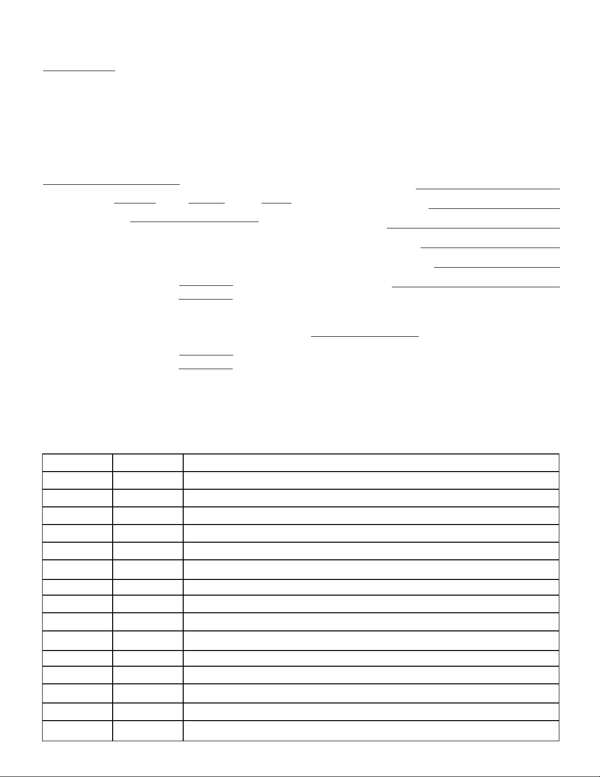
Job Information
Job Name: ________________________________________
Address:__________________________________________
City: ________________ State: ________ Zip: __________
Phone: __________________ Fax: ____________________
Contact Person: ___________________________________
Service Organization: ______________________________
Address:__________________________________________
City: ________________ State: ________ Zip: __________
Phone: __________________ Fax: ____________________
Work Done By:____________________________________
Name Plate Information
Model: ___________________________________________
Volts: ___________ Hertz: __________ Phase: _________
Min. Circuit Amps: _____________ Mark: _____________
Supply Hp: _____________ Exhaust Hp: ______________
Unit Serial Number:______________________________
Supply Motor Voltage:
Supply Motor Amperage:
Supply Fan rpm:
Exhaust Motor Voltage:
Exhaust Motor Amperage:
Exhaust Fan rpm:
Maintenance
Date Time Notes:
Field Start-Up Documentation
Actual Voltage: Hertz: Phase:
Actual Amperage:
Supply Blower
Rotation ❏ Correct
Air Volume Design
cfm
Actual
cfm
Exhaust Blower
Rotation ❏ Correct
Air Volume Design cfm
Actual cfm
UNIT MAINTENANCE DOCUMENTATION
Page 20
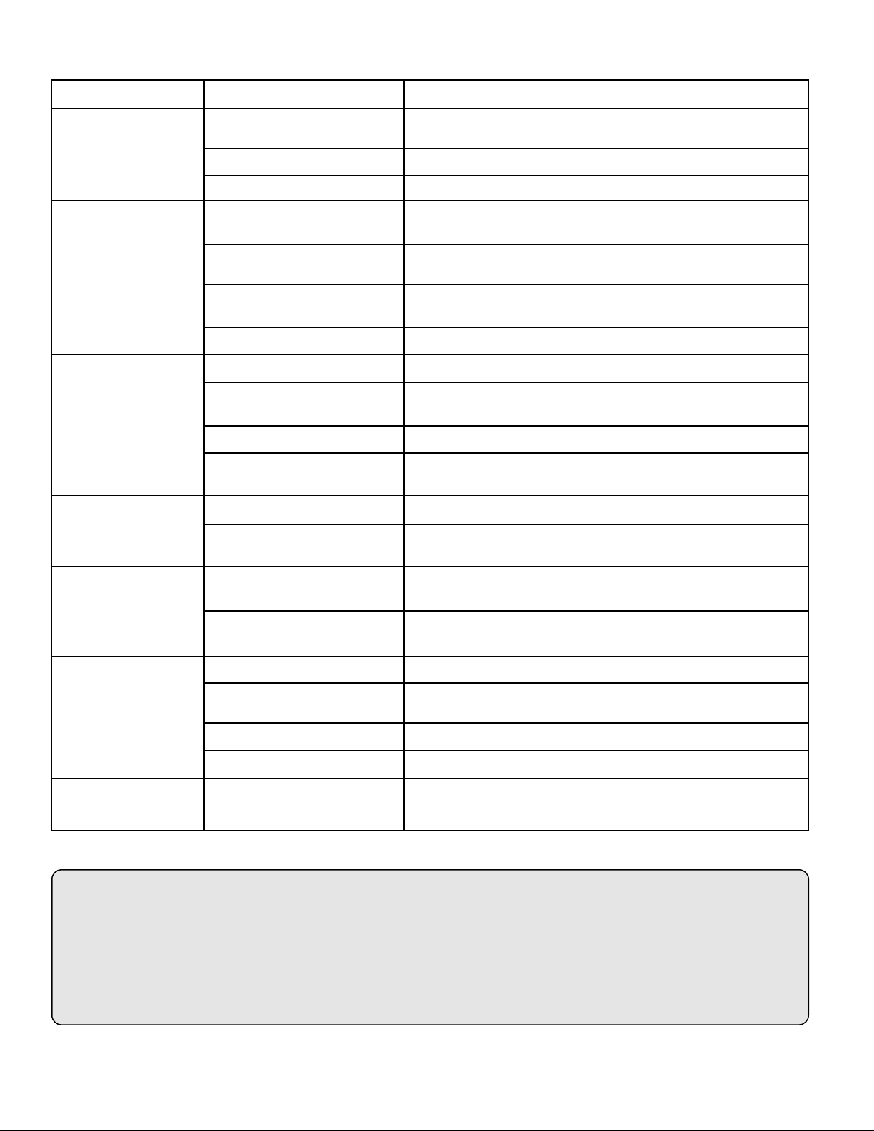
TROUBLE SHOOTING
PROBLEM POSSIBLE CAUSE CORRECTIVE ACTION
Electrical Check fuses/circuit breakers, replace if needed. Check for On/Off
switches. Check for correct supply voltage.
Unit is NOT
Drive Check for broken or loose belts. Tighten loose pulleys.
Operating
Motor Check that the motor hp is correct and not tripping overloads.
Fan Wheel Rubbing on Inlet Adjust wheel and/or inlet cone. Tighten wheel hub or bearing
collars on shaft.
Excessive
Bearings Replace defective bearing(s). Lubricate bearings. Tighten collars
Noise
and fasteners.
Belts Tighten sheaves on motor/fan shaft. Adjust belt tension. Align
sheaves properly (see page 14). Replace worn belts or sheaves.
Wheel Out of Balance Replace or rebalance.
Blower Fan Speed too Low Check for correct drives and rpm’s with catalog data.
Fan wheels are operating For 3 phase see Fan Wheel Rotation on page 13.
backwards. Check blower rotation.
Low
Airflow (cfm)
Dirty filters or energy wheel Follow cleaning procedures on page 17.
High Static Pressure Incorrect fan-to-duct connections. Make sure dampers open
appropriately. Increase fan speed.
Blower Fan Speed too High Check for correct fan rpm.
High
Airflow (cfm) Low Static Pressure Make sure grilles, filters, and access doors are installed. Decrease
fan speed.
Blower fan motor overloads are Decrease fan speed.
One or Both Blowers tripping
Turn Off
Exhaust Only or On/Off frost Adjust frost temperature sensor set point as needed.
control sensors are tripping
Air seals too tight See Energy Recovery Wheel on page 12.
Energy Wheel
"Economizer" temperature Adjust temperature or enthalpy set points as needed.
Does NOT Turn
sensors are operating
No power to wheel motor Make sure wheel drive is plugged in. Verify power is available.
Wheel Drive Belt Check for loose or broken belts. Replace belts (consult factory).
Energy Wheel Runs
Wheel motor overloads are Recheck air seals, make sure they are not to tight. See Energy
Intermittently
tripping, due to rubbing Recovery Wheel on page 12.
between wheel and air seals
* Always provide the unit model and serial number when requesting parts or service information. * Always check motor amps and compare to nameplate rating.
Warranty
Greenheck warrants this equipment to be free from defects in material and workmanship for a period of one year from the
purchase date. The energy recovery wheel is warranted to be free from defects in material and workmanship for a period of
five years from the purchase date. Any units or parts which prove defective during the warranty period will be replaced at
our option when returned to our factory, transportation prepaid.
Motors are warranted by the motor manufacturer for a period of one year. Should motors furnished by Greenheck prove
defective during this period, they should be returned to the nearest authorized motor service station. Greenheck will not be
responsible for any removal or installation costs.
Due to continuing product development, Greenheck has the right to change specifications without notice
IOM ERV - FS
Rev 4 September 2000
Copyright © 2000 Greenheck Fan Corp.
 Loading...