

Page 1
®
ASSEMBLY INSTRUCTIONS
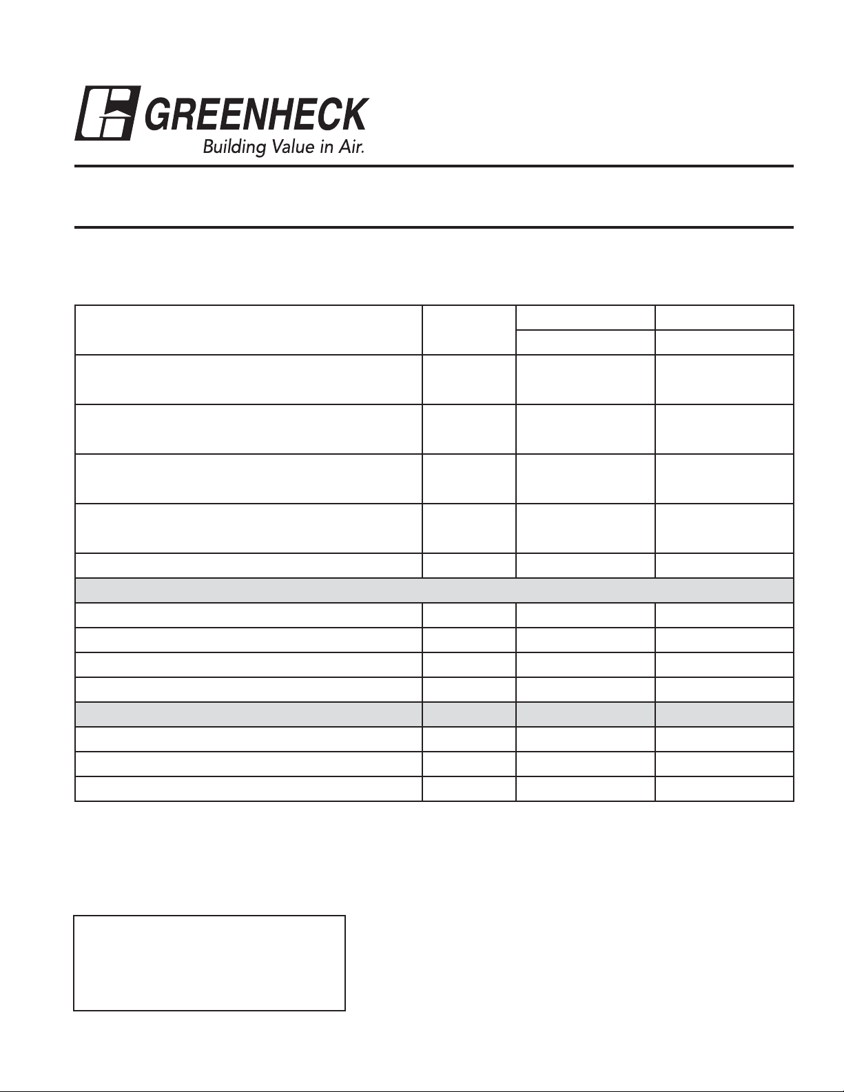
STEP 1: Unpack and Inspect Parts
Document 460988
Roof Curb and Duct Adapter
Models ERV-522/90 & ERV-582/120
Part Description Quantity
ERV-522/90 ERV-582/120
P/N P/N
Roof Curb Kit 12 in. high 1 851721 851822
16 in. high 1 851720 851823
1. End Channel 12 in. high 2 700197 702035
16 in. high 2 700253 702036
2. Non-Supply Side Channel 12 in. high 2 657259 702039
16 in. high 2 657262 702040
3. Supply Side Channel 12 in. high 2 657254 702037
16 in. high 2 657261 702038
4. Center Channel 12 in. & 16 in. high 1 700196 702041
Duct Adapter
5. Inner Duct Channel 1 700195 702042
6. Inner Cross Channel 1 700199 702045
7. Duct Cross Channel 1 700193 702044
8. Outer Duct Channel 1 700194 702043
Hardware Kit
3
/8-16 x 3/4 Serrated Flange Bolts
3
/8-16 x 3/4 Serrated Flange Nuts
(12 in. & 16 in. high curbs)
(for curb & duct adapter) 1 851549 851549
24 415459 415459
24 415457 415457
Screws, SMS (A) 12 x 0.625 (IHH) 16 415180 415180
Note: Hardware kit for the 12 in. high and 16 in. high roof curb are the same.
Tools Recommended for Assembly
• Cordless drill
• 5/16 in. Nut setter
9
•
• Open or Closed 9/16 in. wrench
• Awl — for hole alignment
/16 in. Nut setter
Page 2
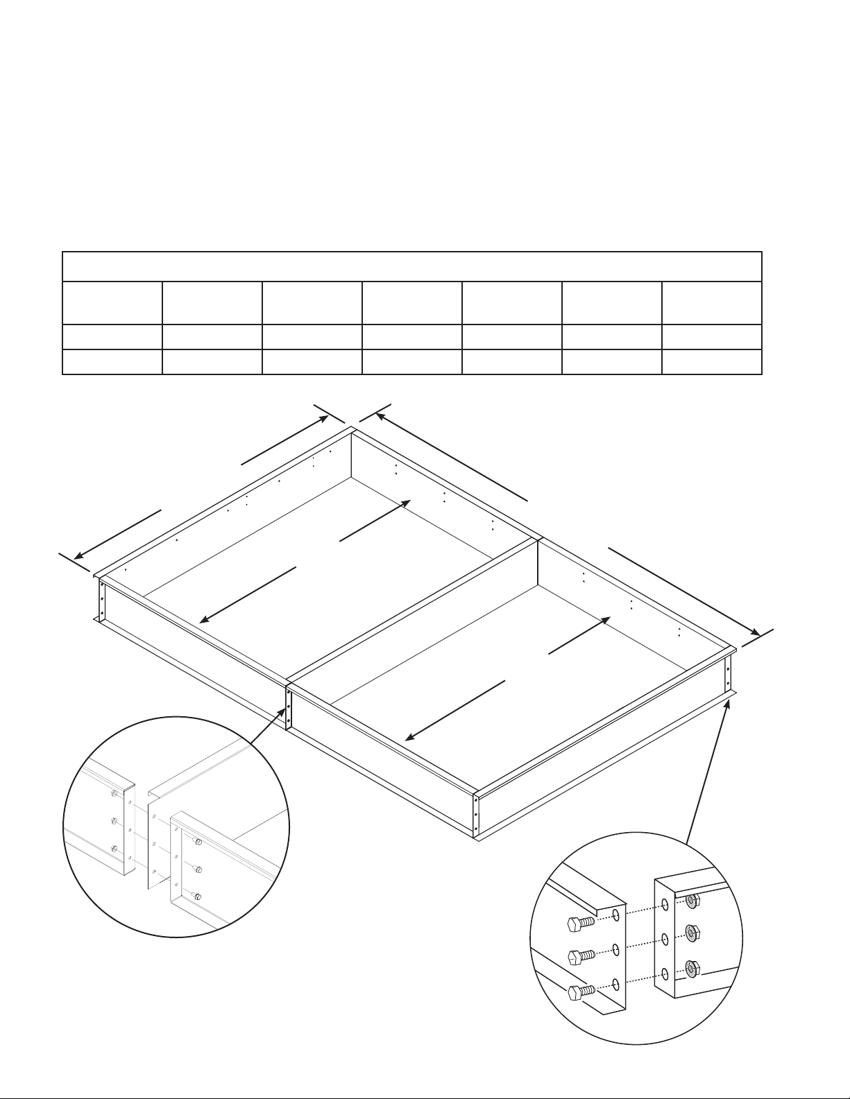
STEP 2: Assemble Main Curb
Hardware Required: (24) 3/8-16 x 3/4 Serrated Flange Bolts
(24)
(2) End Channels
(1) Center Channel
(2) Non-Supply Side Channels
(2) Supply Side Channels
Instructions: • See Main Curb Assembly for positioning the Side, Center, and End Channels.
• Align the holes and fasten as shown below.
3/
8
-16 x 3/4 Serrated Flange Nuts
Channel Lengths and Overall Curb Dimensions
Non-Supply
Length
ERV-522/90 58.37 58.63 80.50 80.50 120.50 80.50
ERV-582/120 64.88 73.87 92.75 92.75 142.25 92.75
All dimensions in inches.
Supply
Length
End
Length
Center
Length
LW
Main Curb Assembly
W
L
Non-Supply Side Channels
Supply Side Channels
Side and center channels
fasten together, as shown.
End and side channels
fasten together, as shown.
2
End
Page 3

A
B
IMPORTANT! The following steps are for ductwork support. These steps are required only
C
D
if the ductwork will be installed prior to the ERV unit.
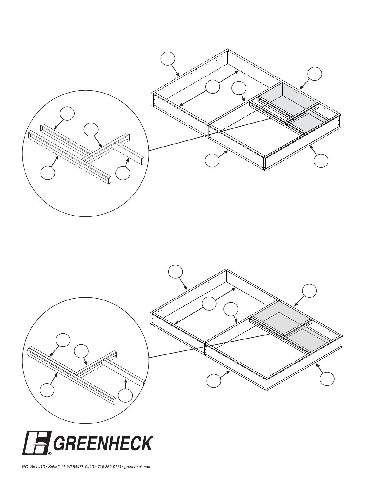
STEP 3: Fastening Inner Cross and Outer Duct Channel (Items 6 & 8)
Hardware Required: (8) Screws, SMS (A) 12 x 0.625 (IHH)
(1) Inner Cross Channel
(1) Outer Duct Channel
Instructions: • Position the Outer Duct
Channel as depicted.
• Align the holes and fasten
using (4) 12 x 0.625 (IHH)
screws.
• Position the Inner Cross
Channel as depicted.
• Align the holes and fasten
using (4) 12 x 0.625 (IHH)
screws.
Supply
Side
Outer Duct
Channel
Inner Cross
Channel
Inner Cross
Length
ERV-522/90 23.50 58.60 22.13 25.25
ERV-582/120 34.50 74.00 35.75 36.25
All dimensions in inches.
Outer Duct
Length
AB
STEP 4: Fastening Inner Duct and Duct Cross Channels (Items 5 & 7)
Hardware Required: (8) Screws, SMS (A) 12 x 0.625 (IHH)
(1) Duct Cross Channel
(1) Inner Duct Channel
Instructions: • Position the Inner Duct
Channel as depicted.
• Align the holes and fasten
using (4) 12 x 0.625 (IHH)
screws.
• Position the Duct Cross
Channel as depicted.
• Align the holes and fasten
using (4) 12 x 0.625 (IHH)
screws.
Supply
Side
Inner Duct
Channel
Duct Cross
Channel
Duct Cross
Length
ERV-522/90 22.13 36.50 27.70 12.75
ERV-582/120 35.75 38.12 32.25 13.00
All dimensions in inches.
Inner Duct
Length
CD
3
Page 4
ERV-522/90: Final Roof Curb Assembly
1
Duct Adapter Assembly
5
6
3
2
4
Exhaust
Inlet
Supply
Outlet
8
7
ERV-582/120: Final Roof Curb Assembly
1
Duct Adapter Assembly
5
3
1
3
2
4
Exhaust
Inlet
Supply
Outlet
6
3
1
8
7
Roof Curb and Duct Adapter Assembly, Rev. 5, April 2013
460988 • ERV-522/90 and ERV-582/120
Copyright © 2013 Greenheck Fan Corp.
 Loading...