

Page 1
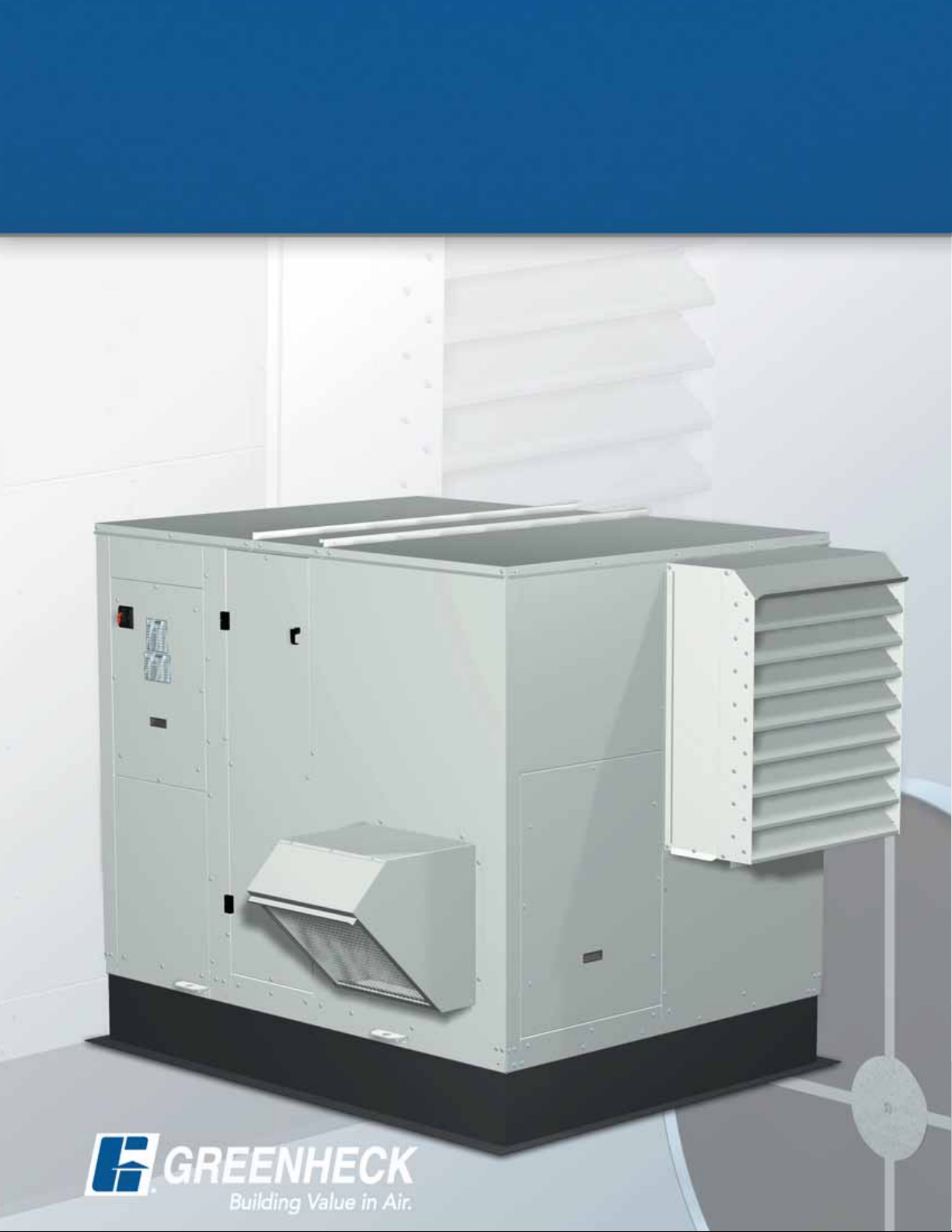
Energy Recovery Ventilator with Heating
Model ERH
• Commercial • Institutional
• 10,000 cfm
• 1.5 in. wg external static pressure
April
2005
Page 2
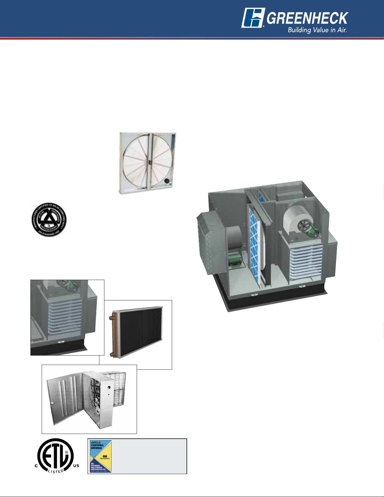
Product Features
Model ERH
Energy Recovery Ventilator With Heating
With the ERH, you save money with the total energy
wheel and get the convenience of supplemental
heating. The ERH provides preconditioned air in the
summer and space neutral air in the winter which is
ideal if your climate has prominent summer and
winter seasons. For applications requiring cooling,
refer to Model ERCH.
Model ERH shown with optional
indirect gas heater, supply
filters, and exhaust filters.
2
Total Energy Wheel recovers
energy from the exhaust air
stream and transfers it to the
supply air stream. The wheel is
constructed of a light-weight
polymer and a permanently
bonded silica gel desiccant.
Eight wheel segments are
easily removable for cleaning.
Optional Tempering Section provides supplemental
heating of the outdoor air after pre-conditioning by
the energy wheel. Tempering options include indirect
gas, hot water, and electric.
Standard Construction
With every ERH, you automatically receive:
✓ Forward Curved Blowers & Motor Assemblies
mounted on isolation bases with neoprene
vibration isolators for smooth, quiet operation.
✓ A Control Box furnished with motor starters for
the supply blower, exhaust blower, and energy
wheel motors.
✓ Double Wall Housing which provides a
galvanized steel-lined interior to prevent exposure
of the insulation to the airstream.
✓ Access Doors to blowers, filters, energy wheel,
and heater section to simplify inspection and
routine service.
✓ Single Point Wiring with a disconnect switch and
low voltage terminal strip.
❏
❏
❏
❏
❏
Hot Water
Indirect Gas
Electric
You Get a Product that is Simple to Operate:
• Fresh outdoor air is pre-conditioned by the total
enthalpy wheel, recovering a majority of the energy
from the exhaust air.
- Saves 3-4 tons of cooling per 1000 cfm
- Saves 50-60 MBH of heating per 1000 cfm
• The heating section further tempers cold outdoor
air to desired conditions.
You Get a Product that is Flexible:
• Four housing sizes
• Airflow capacities up to 10,000 cfm
• External static pressures up to 1.5 in. wg
Greenheck certifies that the ERH models
shown herein are licensed to bear the
AMCA seal. The ratings shown are based
on tests and procedures performed in
accordance with AMCA publication 211
and comply with the requirements of the
AMCA Certified Ratings Program.
Energy recovery wheels certified by the ARI Airto-Air Energy Recovery Ventilation Equipment
Certification Program in accordance with ARI
Standard 1060. Actual performance in
packaged equipment may vary. Certified
Ratings are available in the Certified Product
Directory at http://www.ari.org/directories/erv
Page 3
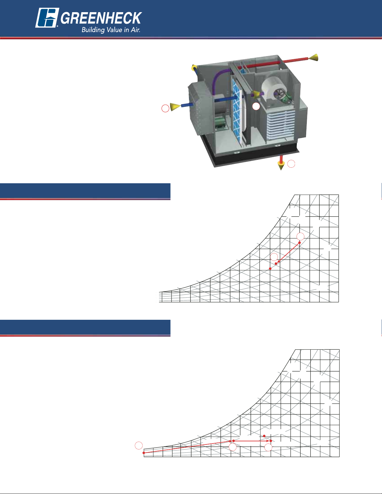
1. Outdoor air enters ERH unit.
2. The energy recovery wheel
cools and dehumidifies
outdoor air using energy
from the exhaust air stream.
Load is reduced by 3 to 4
tons per 1,000 cfm for
many climates.
20 30 40 50 60 70 80 90 100
30
40
50
60
70
80
180
160
140
120
100
80
60
40
20
Specific Humidity
Dry Bulb Temp.
Wet Bulb Temp.
9
0%
70%
50%
30%
10%
Supply Air
Room Air
Outdoor Air
The ERH preconditions
outdoor air for summer
operation. For winter
operation, a variety of
heating options are available
to expand the tempering
capabilities of the energy
recovery wheel.
See below for a description
of the summer and winter
processes along with a
psychrometric illustration.
The numbers on the drawing
at the right correspond to
the numbers on the
psychrometric charts.
Whether a design day or
part load day, the ERH
lowers the temperature
and moisture levels of
summer outdoor air
prior to entering the
ventilation system. This
means you can
downsize the cooling
equipment
and provide
better humidity control
to the space.
2
1
The ERH preconditions
winter outdoor air
typically to 45-65°F. If
your design requires
additional heating, three
heating options are
available:
• Electric
• Hot Water
• Indirect Gas
1. Outdoor air enters ERH unit.
2. The energy recovery wheel heats and
humidifies winter outdoor air using energy
from the exhaust air stream. Heating bills
are significantly reduced and overly dry
indoor conditions are eliminated.
3. The heating coil or furnace
provides supplemental heating
to further treat the outdoor
air to desired supply
conditions.
30
40
50
60
70
80
180
160
140
120
100
80
60
40
20
Specific Humidity
Dry Bulb Temp.
Wet Bulb T
emp.
90%
70%
50%
30%
10%
Supply Air
Room Air
Outdoor Air
Wheel
Heating
Coil
10 20 30 40 50 60 70 80 90 100
110
2
3
1
Tempering Capabilities
3
Winter
2
1
3
Typical Winter
operation.
Fresh Outdoor Air
Exhaust Air
from Space
Summer
Page 4

Air Performance
4
RPM 1141 1344 1498
1000 1142
BHP 0.36 0.51 0.53
RPM 1265 1426 1578 1857
1300 1485
BHP 0.55 0.72 0.90 1.05
RPM 1418 1553 1684 1934 2189
1600 1828
BHP 0.87 1.03 1.21 1.67 2.17
CFM
OV
EXTERNAL STATIC PRESSURE in inches of WG
0.50 0.75 1.00 1.50 2.00 2.50 3.00 3.50
ERH-20M
RPM 1308 1446 1575 1816
1600 1828
BHP 0.74 0.89 1.04 1.37
RPM 1453 1574 1691 1907 2108 2306
1900 2171
BHP 1.10 1.27 1.45 1.80 2.19 2.65
RPM 1608 1717 1820 2020 2205 2375
2200 2514
BHP 1.57 1.77 1.96 2.39 2.79 3.20
CFM
OV
EXTERNAL STATIC PRESSURE in inches of WG
0.50 0.75 1.00 1.50 2.00 2.50 3.00 3.50
ERH-20H
RPM 797 892 986 1166 1329
2200 2109
BHP 0.68 0.81 0.96 1.29 1.65
RPM 900 977 1053 1209 1359 1494 1628
2700 2588
BHP 1.10 1.25 1.40 1.77 2.18 2.58 3.03
RPM 1010 1079 1143 1274 1406 1533 1655 1768
3200 3068
BHP 1.67 1.87 2.04 2.41 2.86 3.33 3.82 4.29
CFM
OV
EXTERNAL STATIC PRESSURE in inches of WG
0.50 0.75 1.00 1.50 2.00 2.50 3.00 3.50
ERH-45L
RPM 900 989 1071 1220 1360 1495
3200 2184
BHP 1.17 1.34 1.53 1.92 2.35 2.83
RPM 1004 1083 1157 1297 1422 1542 1654 1769
3800 2593
BHP 1.79 1.99 2.20 2.64 3.11 3.61 4.12 4.70
RPM 1114 1185 1252 1380 1499 1609 1713 1815
4400 3003
BHP 2.60 2.85 3.08 3.57 4.09 4.64 5.18 5.78
CFM
OV
EXTERNAL STATIC PRESSURE in inches of WG
0.50 0.75 1.00 1.50 2.00 2.50 3.00 3.50
ERH-45H
RPM 749 832 906 1038 1155
4200 1989
BHP 1.54 1.82 2.10 2.65 3.21
RPM 839 913 982 1107 1216 1318 1412 1520
5100 2415
BHP 2.43 2.77 3.11 3.80 4.45 5.15 5.81 6.73
RPM 940 1003 1065 1181 1287 1382 1472 1558
6000 2842
BHP 3.67 4.05 4.45 5.26 6.06 6.84 7.64 8.44
CFM
OV
EXTERNAL STATIC PRESSURE in inches of WG
0.50 0.75 1.00 1.50 2.00 2.50 3.00 3.50
ERH-55H
RPM 612 682 746 862 962 1058
6000 2066
BHP 1.99 2.37 2.75 3.52 4.33 5.21
RPM 723 783 841 941 1036 1122 1202 1275
8000 2755
BHP 3.91 4.41 4.95 5.94 6.97 7.98 9.08 10.14
RPM 845 897 946 1040 1124 1201 1277 1348
10,000 3444
BHP 7.00 7.56 8.18 9.50 10.78 12.00 13.29 14.52
CFM
OV
EXTERNAL STATIC PRESSURE in inches of WG
0.50 0.75 1.00 1.50 2.00 2.50 3.00 3.50
ERH-90H
Greenheck certifies that the ERH models shown
herein are licensed to bear the AMCA seal. The
ratings shown are based on tests and procedures
performed in accordance with AMCA publication
211 and comply with the requirements of the
AMCA Certified Ratings Program.
Gross supply air performance ratings (airflow, pressure, and power)
are at port 2 with port 1, port 3 and port 4 at 0.0 in. wg. Gross
exhaust air performance ratings (airflow, pressure, and power) are to
port 3 with port 1, port 2 and port 4 at 0.0 in. wg. Power rating (BHP)
does not include drive losses. Performance ratings do not include the
effects of appurtenances in the airstream.
Page 5

Intake & Discharge
Options
With the ERH, you have many air intake and
discharge options available to simplify duct
layout for rooftop and equipment room
installations. Refer to the table below for the
intake and discharge locations available for
outdoor air (OA) and exhaust air (EA).
Bottom Top Side End
OA Intake X X
OA Discharge X X X
1
X
2
EA Intake X X X
EA Discharge X X X
Exhaust
Intake
Exhaust
Discharge
Outdoor Air
Intake
Outdoor Air
Discharge
Bottom
Bottom
End
End
To p
To p
To p
To p
End
Side
Filter Pressure Drop (30%eff.)
The air performance data on page 4 accounts for the pressure drop across the energy recovery wheel and the
internal housing losses, but does not include pressure drop for filters or tempering options. Add filter and/or
tempering option pressure drop (from tables below) to external static pressure to determine correct rpm and
horsepower.
NOTE: Coil data assumes 1 row heating coils.
Pressure Drop
Model CFM
(in. wg)
1000 0.04
ERH-20
2200 0.22
2200 0.06
ERH-45
4400 0.24
4200 0.09
ERH-55
6000 0.18
6000 0.10
ERH-90
10,000 0.27
Tempering Options Pressure Drop
Heating Coil Indirect Gas
Model CFM
(in. wg) (in. wg)
1000 0.02 0.03
ERH-20
2200 0.08 0.13
2200 0.04 0.09
ERH-45
4400 0.08 0.34
4200 0.04 0.10
ERH-55
6000 0.08 0.26
6000 0.03 0.24
ERH-90
10,000 0.08 0.55
End
Air Performance
5
Side
1
Side OA Discharge is ONLY available with
the Indirect Gas (IG) heater.
2
End OA Discharge is NOT available with
the Indirect Gas (IG) heater.
Page 6

6
Accessories
Weatherhoods
A louvered intake hood
with 2-inch aluminum
mesh filters, and an
exhaust hood with an
integral backdraft damper
are available.
Dampers - Internally Mounted
A variety of motorized control
dampers are available. Intake
and exhaust dampers are
internally mounted at the
outdoor and exhaust air
inlets. Dampers are factory
wired to a single point power
disconnect.
Filters
Standard size 2-inch, pleated, medium efficiency
filters and filter racks are available for outdoor air
and/or exhaust air streams.
Frost Control
In cold climates, the recovery wheel may develop
frost, which will decrease airflow. Three factory
mounted options are available to address frosting:
• Timed Exhaust Frost Control
The timed exhaust frost control turns the supply
blower off and on intermittently. Control is triggered
by an outdoor air temperature set point in
conjunction with an increased pressure drop across
the energy wheel.
• Modulating Wheel Frost Control
The modulating wheel frost control enables
continuous unit operation. A variable frequency
drive (VFD) reduces wheel speed when the outdoor
air temperature falls below the frost threshold set
point and upon an increase in the differential
pressure across the energy wheel. The temperature
and pressure differential set points are set at the
factory, but are field-adjustable. The VFD will be
fully programmed and wired at the factory.
• Preheat Frost Control
The preheat frost control enables continuous unit
operation. An electric heater warms the outdoor air
above the frost threshold before it enters the energy
recovery wheel. Control is triggered by the outdoor
air temperature set point in conjunction with
increased pressure drop across the energy wheel.
Rotation Sensor
Senses when a wheel rotation failure occurs and
sends a signal to an indicator light. The light is
available on a remote control panel from the factory.
Discharge Temperature Control
Manual control is available
allowing the user to adjust the
discharge temperature off the
heater as required.
Dirty Filter Sensors
Pressure taps sense excessive pressure drop across
the filter and send a signal to a dirty filter indicator
light. Light and control box available from the factory.
Economizer Control (Free Cooling)
When cool outdoor air is available, the energy wheel
may be controlled to provide free cooling.
Economizer operation can be initiated by the unit
sensors alone or in conjuction with a call for cooling
(field wired) Two factory installed options are
available.
• Wheel Off: De-energizes the wheel when the
outdoor temperature is below the field adjustable
set point (enthalpy sensor also available). An
automatic economizer override is included to
engage the wheel for winter heating operation.
• Wheel Modulation: Modulates the energy
recovery wheel to maintain a 55°F discharge
temperature during economizer operation.
Note: Control centers in Greenheck energy recovery
ventilators enable the control of the energy wheel
and fans via 24-volt control signals (by others).
Controls by others may be preferred when air
handling units are equipped with an economizer
section.
Variable Air Volume
Model ERH utilizes belt driven
blowers that are available with
optional variable frequency
drives.
Additional Accessories:
• Remote Panels
• GFCI Service Outlet (control power by others)
• Service Lights (control power by others)
• Spare Wheel Segments
• Roof Curbs
• Painted Exteriors
• Duct Flanges
• Sensible Wheel Only
Page 7

General: Energy Recovery Ventilator shall be as
manufactured by “Greenheck” or approved equal provided
all specifications are met. Greenheck Model ERH is used as
the basis of design. Units shall be Listed per ANSI/UL 1995,
Heating and Cooling Equipment. Ventilators shall bear the
AMCA Certified Ratings Seal for air performance. Energy
transfer ratings of the energy recovery wheel shall be ARI
Certified. Performance shall be as scheduled on plans.
Exhaust discharge and outside air intake shall not be located
on the same side on roof top units.
Unit Casing and Frames: Unit shall be of internal frame
type construction of galvanized steel. Frame and panels shall
be G90 galvanized steel. All panels exposed to the weather
shall be a minimum of 18 gauge galvanized steel. Unit shall
be internally lined with galvanized sheet metal creating a
double wall. Where top panels are joined there shall be an
overlapping, standing seam to insure positive weather
protection. All metal-to-metal seams shall be factory sealed,
requiring no caulking at job site. Permatector exterior finish
is available for outdoor units. Unit base to be designed for
curb mounting. Unit base shall overhang the curb for a
positive seal against water run-off.
Weatherhoods: Weatherhoods shall be the same finish as
the unit. Outdoor air weatherhood shall incorporate a
louvered design and moisture eliminator. Weatherhoods shall
be tested in accordance with AMCA Standard 500-L to
prevent water penetration up to 3 in/hr at 29 mph.
Insulation: Unit casing to be insulated with 1 inch fiberglass.
Insulation shall meet requirements of NFPA 90A and tested
to meet UL 181 erosion requirements. Insulation to be
enclosed in double wall construction.
Energy Recovery Wheel: Wheel shall be of the enthalpy
type for both sensible and latent heat recovery and be
designed to insure laminar flow. Energy transfer ratings must
be ARI Certified to Standard 1060 and bear the ARI
Certification symbol for ARI Air-to-Air Energy Recovery
Ventilation Equipment Certification Program based on ARI
1060. Ratings “in accordance with 1060” without certification
are not acceptable. Desiccant shall be silica gel for
maximum latent energy transfer. Wheel shall be constructed
of lightweight polymer media to minimize shaft and bearing
loads. Polymer media shall be mounted in a stainless steel
rotor for corrosion resistance.
Wheel design shall consist of removable segments for ease
of service and/or cleaning. Silica gel desiccant shall be
permanently bonded to wheel media to retain latent heat
capability after cleaning. Wheels with sprayed on desiccant
coatings are not acceptable. Wheels with desiccant applied
after wheel formation are not acceptable. Energy recovery
device shall transfer moisture entirely in the vapor phase.
Energy recovery drive belt material shall be high strength
urethane and shall be factory installed in a pre-stretched
state, eliminating the need for field belt tension adjustment.
Link style belts are not acceptable.
Access Doors: All components shall be easily accessible
through removable doors for exhaust, supply, filter, and
damper compartments. Energy recovery wheels (smaller
than 58 inches) shall be mounted in a slide-out track for ease
of inspection, removal, and cleaning.
Roof Curbs: Roof curb to be supplied by unit manufacturer
for field assembly. Curb shall consist of die formed
galvanized steel sections. Curb shall be full perimeter type
with gasketing provided for field installation between curb
and unit base.
Fan Sections: Centrifugal fans to be double width, double
inlet, forward curved type. All blower wheels shall be
statically and dynamically balanced. Ground and polished
steel fan shafts shall be mounted in permanently lubricated,
sealed ball bearing pillow blocks. Bearings shall be selected
for a minimum (L10) life in excess of 100,000 hours at
maximum cataloged operating speeds. Separate motors for
exhaust and supply blowers shall be provided. Adjustable
sheaves on belt-driven fans with motors less than 10 hp shall
allow independent balancing of exhaust and supply airflow.
Fan and motor assemblies are mounted to unit base with
neoprene isolators as standard. Fans shall be located in
draw-through position in reference to the energy recovery
wheel.
Motors and Drives: Motors shall be energy efficient,
complying with EPACT standards, for single speed ODP and
TE enclosures. Motors shall be permanently lubricated,
heavy-duty type, matched to the fan load and furnished at
the specified voltage, phase, and enclosure. Drives shall be
sized for a minimum of 150% of driven horsepower. Pulleys
shall be of the fully machined cast type, keyed and securely
attached to the fan wheel and motor shafts; 10 horsepower
and less shall be supplied with an adjustable drive pulley.
Energy wheel motors shall have integral overload protection.
Filters: Supply and exhaust air filters shall be 2-inch thick
pleated fiberglass, 30% efficient and tested to meet UL Class
2. Filter racks shall be die-formed galvanized steel.
Electrical: All internal electrical components shall be factory
wired for single point power connection. Units with electric
reheat will be wired with independent power supply. All
electrical components shall be UL Listed, Approved, or
Classified where applicable and wired in compliance with the
National Electrical Code.
Weatherproof, integral door interlocking disconnect switch,
motor starters, control circuit fusing, control transformer for
24 VAC circuit, and terminal strip shall be supplied as
standard components in the control center. Motor starters
consist of a contactor and Class 20 electronic adjustable
overload protection and shall be provided for all fan motors
in the unit.
Indirect Gas: Indirect fired gas furnace shall be 80%
efficient, UL Certified and Listed per ANSI Z83.8 - 2002,
C.G.A. approved per 2.6 - 2002 and have a blow through fan
design. Furnace shall be capable of operation with natural or
LP gas and have a power venting system. The burner and
heat exchanger shall be constructed of aluminized steel.
Standard furnace features shall include main gas pressure
regulator, main gas valve, electronic staged or electronic
modulating controls, direct spark ignition system, high limit
and a 24 volt control transformer.
Hot Water Coil: Hot water coil shall be factory tested and
rated in accordance with ARI 410. Coils shall have copper
tubes with permanently expanded aluminum fins, 12 fpi or less.
Electric Heat: Electric heat shall be UL listed and circuit
fused per NEC over 48 amps. Heater shall be SCR control,
factory wired and installed. Control will be 24 volt with class
2 transformer. Standard air flow switch to shut down heater
if air ceases to flow across heater.
7
Typical Specifications
Page 8

Unit Size A B C D E F
Approximate Weight
(lbs.)
ERH-20
78 50 56 18 18 9 1000
ERH-45
86 69 66 16 20 11
1800
ERH-55
99 70 76 16 25 11
2500
ERH-90
111 85 96 16 27 11 4500
All dimensions shown are in inches. Actual weight is dependent upon unit configuration
Dimensional Data
Our Warranty
Greenheck warrants this equipment to be free from defects in material and workmanship for a period of one year from the purchase
date. The energy recovery wheel is warranted to be free from defects in material and workmanship for a period of five years from
the purchase date. Any units or parts which prove defective during the warranty period will be replaced at our option when returned
to our factory, transportation prepaid. Motors are warranted by the motor manufacturer for a period of one year. Should motors
furnished by Greenheck prove defective during this period, they should be returned to the nearest authorized motor service station.
Greenheck will not be responsible for any removal or installation costs.
As a result of our commitment to continuous improvement, Greenheck reserves the right to change specifications without notice.
Greenheck P.O. Box 410 • Schofield, WI 54476-0410 • Phone (715) 359-6171 • greenheck.com
Copyright © 2005 Greenheck Fan Corp. • ERH RG Rev. 3 April 2005
Side
View
To p
View
Dimensions and Weight
Hood
Outdoor Air
2 in. filters
Wheel Cassette
FAD
Optional
IG Heater
B
Exhaust
Hood
Outdoor Air Hood
E
Electrical Box
2 in. filters
Wheel Cassette
2 in. filters
C
Optional
IG Heater
 Loading...