

Page 1
Part # 461468
®
Models ERH, ERCH, and ERT
Installation, Operation, and Maintenance Manual
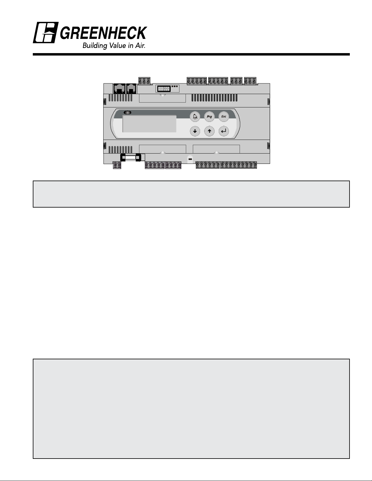
CAREL
pCO2 built-in terminal
WARNING
Disconnect and secure all electrical power to the “OFF” position on the unit prior to inspection or servicing.
Failure to comply with this safety precaution could result in serious injury or death.
Temperature Control Package
Table of Contents
Temperature Control Package Description . . . . . . . . . . . . . . . . . . . . . . . . . . . . . . . . . . . . . . . . . . . . . . . . . . . . . . 2
Sensor Locations...........................................................................2
Sequence of Operation - Summer .............................................................2
Sequence of Operation - Winter ............................................................... 2
Navigating the Controller ....................................................................3
Programming Loops ........................................................................3
Getting Started ............................................................................3
Status Loop ............................................................................... 3
Set Point Loop............................................................................. 4
Time and Holiday Loop ......................................................................5
Unit Set-Up Loop......................................................................... 5-6
Options ..................................................................................7
Controller Wiring ...........................................................................7
Remote Interface Panel......................................................................8
Troubleshooting ...........................................................................8
Warranty
Greenheck warrants this equipment to be free from defects in material and workmanship for a period of one
year from the shipment date. The energy recovery wheel is warranted to be free from defects in material
and workmanship for a period of five years from the shipment date. Any units or parts which prove to be
defective during the warranty period will be repaired or replaced at our option when returned to our factory,
transportation prepaid.
Motors are warranted by the motor manufacturer for a period of one year. Should motors furnished by
Greenheck prove defective during this period, they should be returned to the nearest authorized motor
service station. Greenheck will not be responsible for any removal or installation costs.
As a result of our commitment to continuous improvement, Greenheck reserves the right to change
specifications without notice.
Page 2

Temperature Control Package Description
The Temperature Control Package enables models ERH, ERCH, or ERT to temper outdoor air to desired
temperature and relative humidity. The controller and accompanying sensors are mounted in the unit, wired,
and fully programmed at the factory. Default settings are pre-programmed, but are field adjustable. This unit
has been programmed for either discharge or room control. Discharge control will temper the outdoor air to the
desired discharge condition. Room control will temper the outdoor air to meet the desired room air conditions
with the use of a remote thermostat. An optional humidistat is available for tighter control of room humidity
conditions.
Sensor locations
Outdoor air sensor
1
(summer/winter changeover)
After-wheel temperature sensor
2
(energy savings readout, coil freeze protection)
After-coil cooling temperature sensor (on units
1 432
3
with cooling)
4
Discharge temperature sensor
Summer Sequence of Operation
1. Outdoor air sensor detects high enthalpy and
activates summer operation mode.
2. The energy wheel cools and dehumidifies the
outdoor air.
No Room Thermostat or Humidistat
3a. After-coil temperature sensor sends signal to
controller to regulate condensing unit stages or
chilled water valve. DX or chilled water will cool air
to the specified after-coil set point.
3b. Sensor detects discharge air temperature (for
reheat). Controller adjusts hot water valve, electric
heat, or indirect fired furnace stages to meet the
summer heat setting.
Room Thermostat only
3a. When the room temperature set point is met, the
DX or chilled water coil will cool air to the specified
after-coil set point. If the unit is equipped with
reheat, the air will be reheated to the specified
summer heat setting.
3b. When the room temperature is above the summer
set point, the after-coil temperature will drop to
the specified after-coil override setting and the
discharge temperature will drop to the summer
heat override setting (i.e. turn the heater off) .
4
1
3
Room Humidistat only
3a. When the humidity set point is satisfied, the DX or
chilled water coil will cool air to the specified aftercoil set point. If the unit is equipped with reheat,
the air will be reheated to the specified summer
heat setting.
3b. When the humidity in the space is too high, the DX
or chilled water coil will drop to the specified aftercoil override setting with no change in reheat.
Room Thermostat and Humidistat
3a. When the room temperature and humidity set
points are satisfied, the DX or chilled water coil
will cool air to the specified after-coil set point.
If the unit is equipped with reheat, the air will be
reheated to the specified summer heat setting.
3b. If the temperature is met, but the humidity is high,
the after-coil temperature will drop to the specified
after-coil override setting with no change in reheat.
3c. If the temperature is high (regardless of the
humidity conditions in the space), the after-coil
temperature will drop to the specified after-coil
setting and the discharge temperature will drop
to the summer heat override setting (i.e. turn the
heater off).
Winter Sequence of Operation
1. Sensor detects that the outdoor air enthalpy
has fallen below the summer/winter changeover
enthalpy and activates winter operation mode
which disables the unit’s cooling capabilities.
2. The energy wheel heats and humidifies the
outdoor air.
No Room Thermostat
3. Discharge air sensor senses temperature.
Controller adjusts hot water valve, IG furnace, or
electric heat stages to the winter heat setting.
2
1
4
With Thermostat
3a. When room temperature set point is met, the unit
will discharge air at the winter heat setting.
3b. When room temperature is below the set point, the
unit will discharge air at the heat override setting.
Page 3
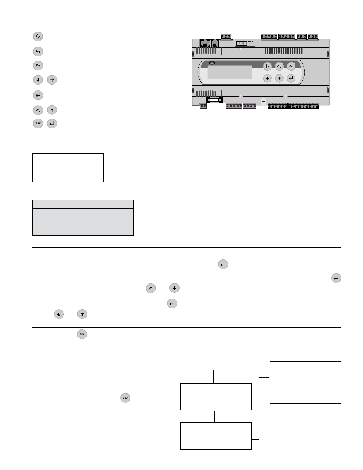
Navigating the Controller
Alarm indicator for water coil freeze protection
Access Set Point loop (See page 4)
Return to the Status screens (See page 3)
Used to scroll through the screens and
change set points.
Used to enter a screen to change set points and
advance to the next set point
Access Unit Set-Up Loop (See pages 5-6)
Access Time and Holiday Loop (See page 5)
Getting Started
Figure 1: Start-up screen
Greenheck Fan Corp.
Version: 2.xx
Temperature Control
Cooling setting: 0
Table 1: Cooling settings
Cooling Method Cooling Setting
0 Chilled Water
1 1-stage DX
2 2-stage DX
CAREL
pCO2 built-in terminal
Figure 1 shows the screen that appears when power is initially
supplied to the controller. It lists the program version and the cooling
setting.
The cooling settings are as shown in Table 1. Compare the settings
on the screen with the options on the unit. Jumpers control all
the settings on the first screen. If there is a discrepancy between
what was ordered and the first screen, compare the wiring on the
controller to the wiring diagram on page 7 or on the unit’s control
center door and adjust accordingly.
To allow the fans and energy wheel in the unit to operate, wire a
switch or jumper between terminals 2 and 3 in the unit’s control
center.
Programming Loops
Several programming loops may be accessed to
change settings on the controller. Navigation through
the loops remains the same throughout the program.
1. To scroll through the screens, use the and
keys.
2. To enter a screen to change a set point, press .
3. Use and to change the set points.
Status Loop
The Status Loop monitors the following conditions:
1) Date and Time
2) System set points
3) Outdoor air conditions
4) Tempering status
5) Energy savings calculation
To enter the Status Loop, press .
4. Press
to advance to the next set point on the
screen.
5. When the set points have been changed, press
until a solid box appears in the upper left corner
of the screen. You may then resume scrolling
through the screens.
Time 00:00
Date: 00/00/00
Sunday
Status
After Wheel: 00.0F
After Coil: 00.0F
Disch Temp: 000.0F
Outdoor Air
Temp: 00.0F
RH: 00.0%
Enthalpy: 00.0B/lb
Tempering Status
Heat (%): 000
Cool Stage 1: Off
Cool Stage 2: Off
Energy Savings
00.0 Tons
3
Page 4

Set Point Loop
All temperature settings may be accessed in the set point loop; default temperature settings are shown on the
left. To access the Set Point Loop, press .
Heat Settings
Summer 60.0F
Winter 70.0F
Heat Override
Summer 45.0F
Winter 95.0F
After Coil Setting
Typical 55.0F
Override 45.0F
Heat Settings
No Room Thermostat
If reheat in the summer is required, adjust the summer heat setting to the desired
discharge temperature. If no reheat is required, set the summer temperature
below the after-coil setting. Adjust the winter set point to the desired discharge
temperature.
With Room Thermostat
The winter heat setting is the temperature the unit will discharge when the
thermostat is satisfied.
Heat Override
Only applicable on units with Room Thermostat
The summer set point is the temperature the unit will discharge when the
thermostat is calling for cooling in the summer. The winter set point is the
temperature the unit will discharge when the unit is calling for heat in the winter.
After-Coil Setting
No Room Thermostat or Humidistat
The typical setting is the desired temperature leaving the cooling coil. The
override setting is not applicable when no thermostat or humidistat is hooked to
the controller.
With Room Thermostat and/or Humidistat
The typical setting is the temperature after the cooling coil when the thermostat
is satisfied. The Override is the after-coil temperature when the room is above the
summer thermostat setting or when the room humidity is higher than the humidity
set point.
Operating Set Points
Change Enth 21.0B/lb
Freeze 35.0F
Economizer
Set 21.0 B/lb
Band 3.0 B/lb
Mode
Unit: Auto
Ret to Fact Defaults
Off
Operating Set Points
Change Enth
Change Enth is the enthalpy at which the controller will switch from summer to
winter operation. This set point has a factory programmed 0.5 btu/lbm deadband built-in to prevent the unit from rapidly switching from summer to winter
operation.
Freeze (Visible with Chilled Water Coil only)
The controller protects chilled water coils from freezing. When conditions before
the coil fall below the field-adjustable set point, the controller opens the water
valves completely, shuts down the supply fan and energy wheel, and sounds an
alarm on the controller in the unit. The controller also outputs a 10 VDC signal that
may be monitored remotely.
Economizer (Visible with Internal Economizer only)
“Set” is the enthalpy at which the energy wheel will be de-energized for “free
cooling” conditions.
“Band” is the range above and below the set point that the wheel will be deenergized. (i.e. For the default setting, the wheel will be de-energized between 18
and 24 Btu/lb.)
Mode
“Auto” allows all features to operate as programmed on the controller.
“On” overrides the functionality of the controller (i.e. the supply blower, exhaust
blower and the energy wheel will always be energized).
Ret to Fact Defaults
“On” returns all settings to the original factory settings. Once “On” is selected and
is pressed, the display resets to the “Off” selection.
WARNING! When Return to Factory Defaults is turned to “On”, the blowers,
4
energy wheel and tempering options will be energized.
Page 5

Time and Holiday Loop
To set the days and times the unit will be operating, access the Time and Holiday Loop by depressing and
simultaneously. Default operation is 24 hours a day, 7 days a week.
Set Time and Date
Time: 00:00
Date: 00/00/00
Operation Hours
24hr Operation: Y
Unit On Time: 07:00
Unit Off Time: 18:00
Operation Days
SUN: Y MON: Y TUE:Y
WED: Y THU: Y
FRI: Y SAT: Y
Holiday Operation
New Years Day: Y
Memorial Day: Y
4th of July: Y
Labor Day: Y
Thanksgiving: Y
Christmas Eve: Y
Christmas Day: Y
Set Time and Date
Set the current time and date. The controller does not adjust for daylight
savings time.
Operation Hours
24 Hour Operation: Set to “Y” if the unit will be operating 24 hours per
day. Set to “N” if the unit will not be. If “N” is selected, set the Unit On
Time and Unit Off time to the time of day the unit will be turning on and off,
respectively. All time settings are in military time.
Operation Days
For each day of the week, set to “Y” if the unit will be running, “N” if it will not.
Holiday Operation
Several holidays are listed. Set to “Y” if the unit will be in operation on those
days, “N” if it will not.
User Holiday: Y
Start: 00/00 MO/DAY
End: 00/00 MO/DAY
Unit Set-Up Loop
Summer Settings
SCFM: 00000
Ret Air Temp: 75.0ºF
Ret Air RH: 0.0%
Winter Settings
SCFM: 00000
Ret Air Temp: 70.0ºF
Ret Air RH: 0.0%
Heat Parameters
Band: 10.0ºF
Integration: 005S
Stage Delay: 05S
(Cont’d on
next page)
User Holiday
One User Holiday may be entered. If “N” is selected, set the day and month
the unit will cease operation and the day and month it will start up again.
Summer / Winter Settings
The controller is programmed to calculate the real-time energy savings
achieved by the use of the energy wheel in tons. The savings may be read
at the controller, or it may be field-wired (see Controller Wiring on page 7)
to track remotely by an analog output from the controller. 0-10 VDC output
corresponds to 0-50 tons of energy savings. To initialize the energy savings
analysis, set the outdoor air SCFM, as well as the return air temperature and
relative humidity. Set these values for both summer and winter.
Heat Parameters
Band The band is the dead-band around the heating set points. The
smaller the band setting, the more sensitive the controller will
be to small temperature changes.
Integration The integration setting (in seconds) is the time necessary for
the integer value to be doubled (i.e. increasing the time setting
decreases the response time).
Stage Delay The stage delay is the minimum time between activation of
stages for electric heat or 2-stage IG furnaces. The default
setting for electric heat is 5 seconds and 60 seconds for IG
furnaces.
5
Page 6

Unit Set-Up Loop (cont’d)
IG Furnace Settings
Min Time On: 2 MIN
IG Furnace Settings (Visible with Indirect Fired Gas Furnace only)
Min Time On The minimum time the furnace stages on.
Cool Parameters
Band: 10.0F
Int: 005S
Time Off: 300S
DX Rotation
Btwn Stages: 060S
Btwn Starts: 300S
Cool Parameters
Band The dead-band around the cooling set points. The smaller the
band setting, the more sensitive the controller will be to small
temperature changes.
Integration The integration setting (in seconds) is the time necessary for
the integer value to be doubled (i.e. increasing the time setting
decreases the response time).
Time Off For DX cooling only. The delay (in seconds) before an “On”
signal is sent to the compressor upon initial power being
supplied to the controller. This feature provides a safety delay
for the compressors to prevent short-cycling during power
interruption to the controller. This delay will be in addition to
any time delays built into the compressor.
DX Rotation (2-stage condensers only)
To avoid short-cycling the condensing unit, a time delay between stages and
a time delay between starts may be set. The condensing unit may also have
delays built-in, so ensure compatibility between the times set in the controller
and condenser.
Btwn Stages Minimum time which must elapse between different
compressors turning on.
Btwn Starts Minimum time which must elapse between a compressor
turning off and turning on again.
The controller has stage auto-rotation programmed into it to equalize the
run time between the stages. On a call for cooling, the first stage will be
activated. If, after the time delay, the cooling load is not met, the second
stage will start. When the cooling load is satisfied, the first stage will turn off
and the second stage will continue to run.
Internal Economizer
Inactive
6
Internal Economizer
Select between Inactive and Active. Internal economizer is recommended
when the energy recovery unit provides 100% of the outdoor air. During
economizer mode, the energy wheel is de-activated to enable “free-cooling”.
Refer to page 4 to set the enthalpy at which economizer mode will be
activated.
The controller also has external economizer capabilities. External economizer
is recommended when the energy recovery unit is used in conjunction with
an air-handling unit that has its own economizer section. When the energy
recovery unit gets the economizer signal from the air handler, the supply
blower, outdoor damper, and energy recovery wheel are de-energized. Refer
to the wiring diagram on page 7 for wiring the external economizer contact
into the controller.
Page 7

Options
Thermostat (Supplied by GREENHECK or others)
A summer and winter thermostat are required for use with this controller. The thermostat contacts must close on
a call for cooling in the summer and heating in the winter.
Humidistat (Supplied by GREENHECK or others)
The humidistat must close on the call for dehumidification.
Water Valves (Supplied by GREENHECK)
Water valves must be Normally Closed and use a 0-10 VDC control input.
Night Setback (Switch supplied by GREENHECK or others)
If a recirculation damper is provided on the unit, a remote switch or timer may be wired into the controller to put
the unit in night setback operation. Night setback will close the outdoor air and discharge damper, shut off the
energy wheel and exhaust blower, and open the recirculation damper to recirculate air during unoccupied mode.
Controller Wiring
T1A Discharge Temp Sensor
Legend
T2A After Coil Temp Sensor
T4A Supply Inlet Enthalpy Sensor
T5A After Wheel Temp Sensor
SW1 External Economizer Switch
SW2 Night Setback Switch
SW1 Unit on/off Switch
TS10 Winter Thermostat (Closes on
call for additional heat)
TS11 Summer Thermostat (Closes on
call for additional cooling)
JS1 Room Dehumidistat (Closes on
a call for dehumidification)
MULTI-VOLTA GE PRIMARY
24 SECONDARY
TS11
TS10
HS1
SW1
SW2
IG HEAT
1 STAGE DX (EN)
2 STAGE DX (EJ)
H4
X1
T1A
T2A
T5A
NTC
M
NTC
G+
TH
T4A
TR1
H3
H1
H2
G
GND
B1
B2
B5
BC4
B4
B3
ID1
ID2
ID3
ID4
ID5
ID6
ID7
ID8
C1
C4
C7
C8
X2
VG
VGOGO
IDC1
NO1
NO2
NO3
NO4
NO5
Y1
Y2
DGH CONTROLLER
Y3
Y4
NO8
NO6
NO7
16
17
18
19
20
H1
H2
H3
DX1
DX2
HWC
CWC
AFA
AES
1
DGH CONTROLLER
HEAT STAGE #1
HEAT STAGE #2
ELEC. HEAT STAGE #3
CONDENSOR STAGE #1
CONDENSOR STAGE #2
(CONDENSOR BY OTHERS)
HOT WATER/STEAM VALVE
(BY OTHERS OR GFC)
CHILLED WATER VALVE
(BY OTHERS OR GFC)
ANALOG FREEZE ALARM
(BY OTHERS)
ANALOG ENERGY SAVINGS
0-50 TONS (BY OTHERS)
S1
2
S1
3333
ENERGY WHEEL
15
SUPPLY FAN
14
EXHAUST FAN
1313
Note: When no jumpers or both jumpers are wired into ID7 and ID8, the unit is setup for chilled water control.
7
Page 8

Remote Interface Panel
on/off alarm enter
If a Remote Interface Panel is ordered, it may be mounted in the
desired location in the building and connected to the controller in
the energy recovery unit by a telephone cable. The controller may
then be monitored and programmed from that location.
The face of the panel contains five buttons, but the face of the
panel may be flipped down to reveal more buttons.
Turns the unit on and off
Signals that the unit is in freeze protection mode
on/off alarm enter
Used to scroll through the screens and change
set points
Used to enter a screen to change set points and advance to the next set point
prog.
Used to access the Set Point loop (under the face of the panel)
set
Return to the Status Screen (under the face of the panel)
Used to access the Time and Holiday Loop
set
prog.
Used to access the Unit Set-Up Loop
Troubleshooting for Temperature Controller
Symptom Possible Cause Corrective Action
Unit not running Unit is in unoccupied mode Ensure date, time, and operational days are
set correctly.
Supply blower not running External economizer functioning
Freeze protection functioning
Exhaust blower not running Unit is in night setback mode Check field mounted night setback switch or
Energy wheel not running External economizer functioning
Internal economizer functioning
Freeze protection functioning
Unit is in night setback mode
Ensure economizer setting is correct.
Check for freeze alarm on the controller.
Check freeze protection set point.
timer for correct settings.
Ensure economizer mode setting is correct.
Check set point for internal economizer.
Check for alarm on the controller and the
freeze protection set point.
Check field mounted night setback switch or
timer for correct settings.
IOM Temperature Control Pkg.
Rev. 1 November 2001
Copyright © 2001 Greenheck Fan Corp.
 Loading...