

Page 1
READ AND SAVE THESE INSTRUCTIONS
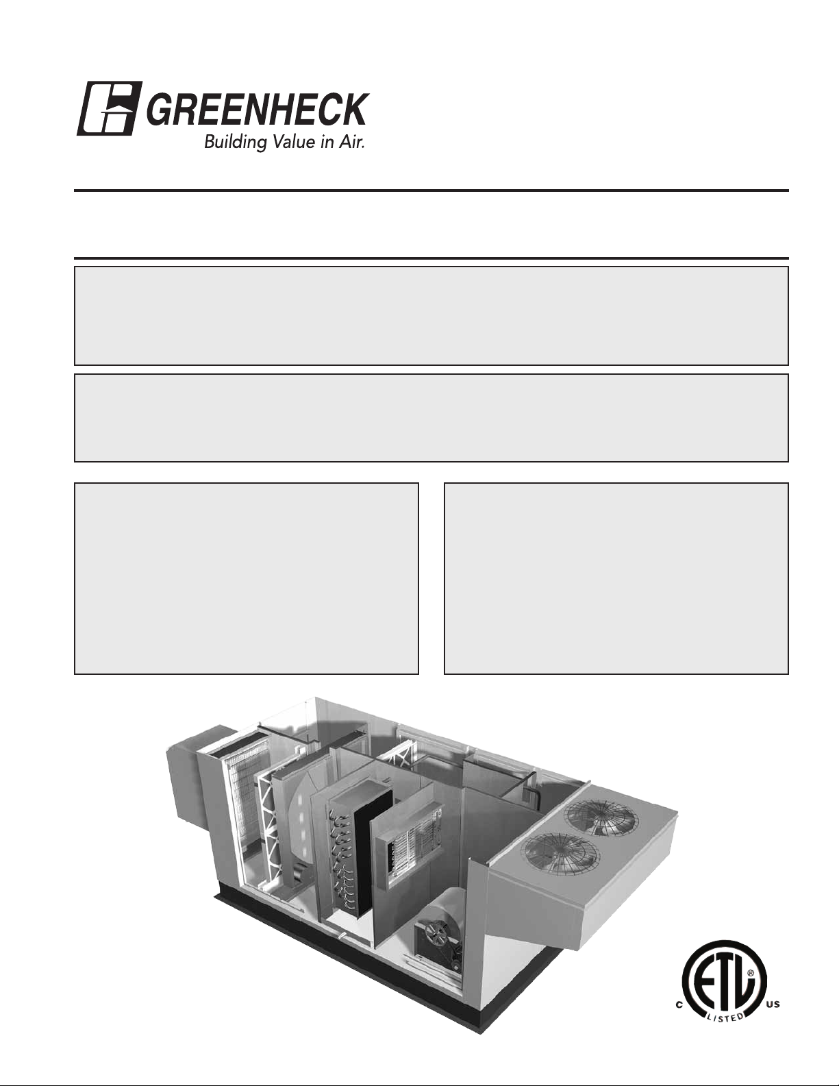
ENERGY RECOVERY UNIT
PART #468151
®
Model ERCH-20, 45, 55 & 90
without DDC Controls
INSTALLATION, OPERATION AND MAINTENANCE MANUAL
RECEIVING AND HANDLING
The ERCH is thoroughly inspected and test run at the factory. However, damage may occur
during shipping and handling. Upon delivery, inspect the unit for both obvious and hidden
damage. If damage is found, record all necessary information on the bill of lading and file a claim
with the final carrier. In addition, ensure all accessory items are present. Some accessory items
are stored inside the unit during shipping.
SAFETY WARNING
Improper installation, adjustment, alteration, service or maintenance can cause property damage,
injury or death. Read this installation, operation, and maintenance manual thoroughly before
installing or servicing this equipment. Installation and service must be performed by a qualified
installer, service agency, or the gas supplier.
WITH PACKAGED DX
INSTALLATION SUPPLEMENTS
Refer to the following installation supplements
ERCH supplied with Indirect Gas (IG) heating:
Model PVF, Indirect Gas Fired Furnaces
for Energy Recovery Units, Part #461006
ERCH Curb Assembly Instruction, Part #468280
SAVE THIS MANUAL
This manual is the property of the
owner, and is required for future
maintenance. This manual should
remain with each ERCH unit when the
job is complete.
Page 2

TABLE OF CONTENTS
Storage and Owners Information ..........2
Basic Operation..........................3
Installation
Lifting .................................4
Unit Weights & Recommended Roof
Openings ............................4
Installation Concerns .....................5
Roof Curb Mounting ...................5-6
Rail Mounting and Ductwork Connections....6
Electrical Information.................. 7-8
Control Center Components ...............8
Service Clearances ......................9
Dimensional Data/Access Door Description . 10
Coil Applications & Drain Trap Info......11-12
Optional Accessories
Electric Heater Application/Operation ......13
Frost Control Application/Operation........14
Economizer Application/Operation .........15
Variable Frequency Drives ...............16
Typical Wiring Diagram ..................17
Sensors and Lights ..................18-19
Remote Control Panel & Wiring ........20-22
Sensors Mounted by Factory .............23
Energy Recovery Unit with Packaged DX
Start-Up Checklist
Unit ...............................24-26
Optional Accessories....................27
Fan ..................................28
Energy Recovery Wheel .................29
Routine Maintenance Checklist...........33
Belts and Motors .......................34
Blower Wheel and Fasteners .............34
Filters ................................35
Coil Maintenance ......................36
Energy Recovery Wheel Maintenance
Accessing Energy Recovery Wheel ........37
Removing Wheel Segments ..............37
Cleaning Wheel Segments ...............38
Parts List ..............................39
Sequence of Operation ...............40-41
Troubleshooting -Airflow .................42
Troubleshooting -General Unit .........43-44
Troubleshooting -Refrigeration Circuit ..45-50
Notes ..................................51
Warranty ...............................52
STORAGE
When a unit is not going to be in service for an extended amount of time, certain procedures should be followed
to keep the fans in proper operating condition.
•Rotatefanwheelmonthlyandpurgegreasefrombearingsonceeverythreemonths
•Coverunitwithtarptoprotectfromdirtandmoisture
(Note: do not use a black tarp as this will promote condensation)
•Energizefanmotoronceeverythreemonths
•Storebeltsflattokeepthemfromwarpingandstretching
•Storeunitinlocationwhichdoesnothavevibration
•Afterstorageperiod,purgegreasefromfanbearingsbeforeputtingfanintoservice
If storage of unit is in a humid, dusty or corrosive atmosphere, rotate the fan and purge the bearings once a
month. Improper storage which results in damage to the unit or components will void the warranty.
OWNER’S INFORMATION
The following summary highlights some important notes to help avoid premature failure and possible voidance
of warranty.
Product Overview
Greenheck ERCH Models integrated with a complete refrigerant system are designed with the purpose of being
a self-contained source for heating and cooling in both commercial and institutional applications. This is done in
a highly efficient manner through the use of a total enthalpy recovery wheel. The wheel allows the compressors
and cooling equipment to be downsized in the unit, therefore being more cost effective to operate. The DX
system comes fully charged from the factory with refrigerant and is ready for installation upon arrival.
The smaller tonnage units (4-9 tons) contain a single compressor, allowing for one stage of cooling. Larger units
(10-30 tons) come standard with two compressors. This allows for staging of compressors to meet a wider
range of outdoor air loads while reducing the amount of cycles per compressor.
Integral Components
All units are provided with an expansion valve, hermetic scroll compressor(s), liquid line filter drier, high
pressure manual reset cutout, low pressure auto-reset cutout, time delays for compressor protection, service/
charging valves, moisture indicating sight glass, and hot gas bypass. The compressors also come standard with
a crankcase heater for additional protection.
2
Page 3
Energy Recovery Unit with Packaged DX
Shutdown Operation
The scroll compressors in this unit are designed to compress gas refrigerant only. To prevent liquid refrigerant
from migrating into and damaging the compressors, each compressor is supplied with a crankcase heater. Prior
to starting the compressors, the heaters must have power to them for 24 hours. Power should never be cut to
these units unless the complete shutdown procedure is followed.
Proper shutdown procedure:
1) Turn off main power supply to the unit
2) Turn thermostat controls to “off” position
3) Restore main power supply to the unit
4) Wait 24 hours prior to turning the thermostat control to the “on” position
Low Ambient Operation
Low ambient operation can cause damage to the refrigerant system. A factory-installed temperature sensor
in the outdoor air intake prevents refrigerant system operation at ambient conditions below 55ºF. Crankcase
heaters will still be engaged provided the main power has not been disconnected. If cooling is desired at
ambient temperatures below 55ºF, economizer operation (wheel start/stop or wheel modulation) should be
employed.
Reduced Airflow – Pumping oil and liquid refrigerant
Lack of maintenance will lead to filters, condensing coils, and evaporator coils building up with dirt and
debris. As this occurs, the airflow through the unit will decrease. Cooling coils are sized to handle a particular
airflow volume. A reduction in airflow can cause the cooling coils to get too cold and may result in excessive
liquid refrigerant return to the compressors. The liquid refrigerant buildup in the compressors will displace the
necessary oil required for proper lubrication. The combination of these two events will significantly reduce the
life of the compressors.
To maintain the proper airflow and system efficiency, follow all procedures in the Maintenance section.
Safety Listing
The ERCH units are listed per ANSI/UL 1995, Heating and Cooling Equipment, and bear the ETL logo.
Environmental Concerns
This equipment contains R22 or R-410a refrigerant. Refer to label on
access door identifying the type of refrigerant in the unit.
R22 is a class II refrigerant that contains HCFC’s. If released, HCFC’s
may reduce the amount of ozone in the atmosphere. This ozone
depletion will result in less protection from the sun and therefore it
is critical to use every precaution necessary to minimize the amount
admitted to our environment.
When working with Greenheck’s fully charged refrigerant system, it is
strongly recommended that caution is undertaken during installation,
operation, and routine maintenance. This caution will help ensure
that minimal amounts of refrigerant are leaked into the atmosphere.
To comply to the U.S. Clean Air Act, anytime there is residual
refrigerant, the proper equipment shall be used and methods should be followed to reclaim the refrigerant so
that it can be recycled, reprocessed, or destroyed.
Do not release refrigerant to the
atmosphere! If required service
procedures include the adding or
removing of refrigerant, the service
technician must comply with all
federal, state and local laws. The
procedures discussed in this manual
should only be performed by a
qualified EPA Certified Technician.
IMPORTANT!
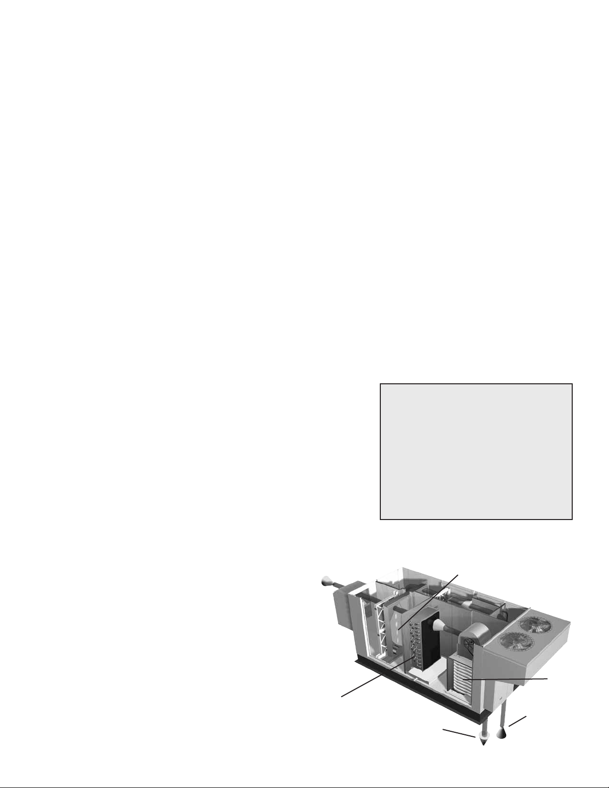
BASIC OPERATION
The ERCH with Packaged DX units bring in
fresh, outdoor air and remove stale, exhaust
air. Prior to discharging the exhaust air, the
energy recovery wheel transfers energy
from the exhaust air to the outdoor air at an
efficiency of 70-80%. Simply put, this unit
preconditions the outdoor air to save money
on heating and cooling costs. These particular
units also have packaged DX cooling and
heating options available after the recovery
wheel to further condition the fresh air.
Outdoor
Air
DX Cooling
Coil
Conditioned Air
sent to space
Energy Recovery Wheel
Optional
Heater
Exhaust Air
from building
3
Page 4
Energy Recovery Unit with Packaged DX
CAUTION!
Unit is designed for Outdoor installation only. Follow all guidelines in this manual for proper installation.
INSTALLATION
The system design and installation should follow accepted industry
practice, such as described in the ASHRAE Handbook.
Adequate space should be left around the unit for piping coils and drains,
filter replacement, and maintenance. Sufficient space should be provided
on the side of the unit for routine service and component removal should
that become necessary.
See Service Clearances/Access Panel Locations section for more details.
SAFETY WARNING
All factory provided lifting
lugs must be used when
lifting the units. Failure to
comply with this safety
precaution could result in
property damage, serious
injury, or death.
HANDLING
While this unit was constructed with quality and dependability in mind, damage still may occur during
handling of the unit for installation. Exercise extreme caution to prevent any damage from occurring to the
refrigerant system. This unit contains a system pressurized with refrigerant that if damaged, could leak into
the atmosphere or cause bodily harm due to the extreme cold nature of expanding refrigerant. Use protective
equipment such as gloves and safety glasses to minimize or prevent injury in case of a system leak during
installation.
LIFTING
1) Before lifting, be sure that all shipping material has been
removed from unit.
2) To assist in determining rigging requirements, weights are
shown below.
3) Unit must be lifted by all lifting lugs provided on base
structure.
4) Rigger to use suitable mating hardware to attach to unit
lifting lugs.
5) Spreader bar(s) must span the unit to prevent damage to
the cabinet by the lift cables.
6) Always test-lift the unit to check for proper balance and
rigging before hoisting to desired location.
7) Never lift units by weatherhoods.
8) Never lift units in windy conditions.
9) Preparation of curb and roof openings should be completed
prior to lifting unit to the roof.
10) Check to be sure that gasketing (supplied by others) has
been applied to the curb prior to lifting the unit and setting
on curb.
11) Do not use fork lifts for handling unit.
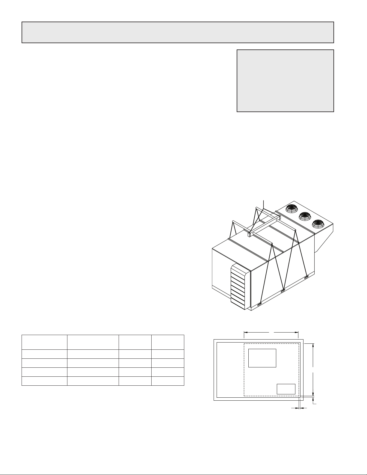
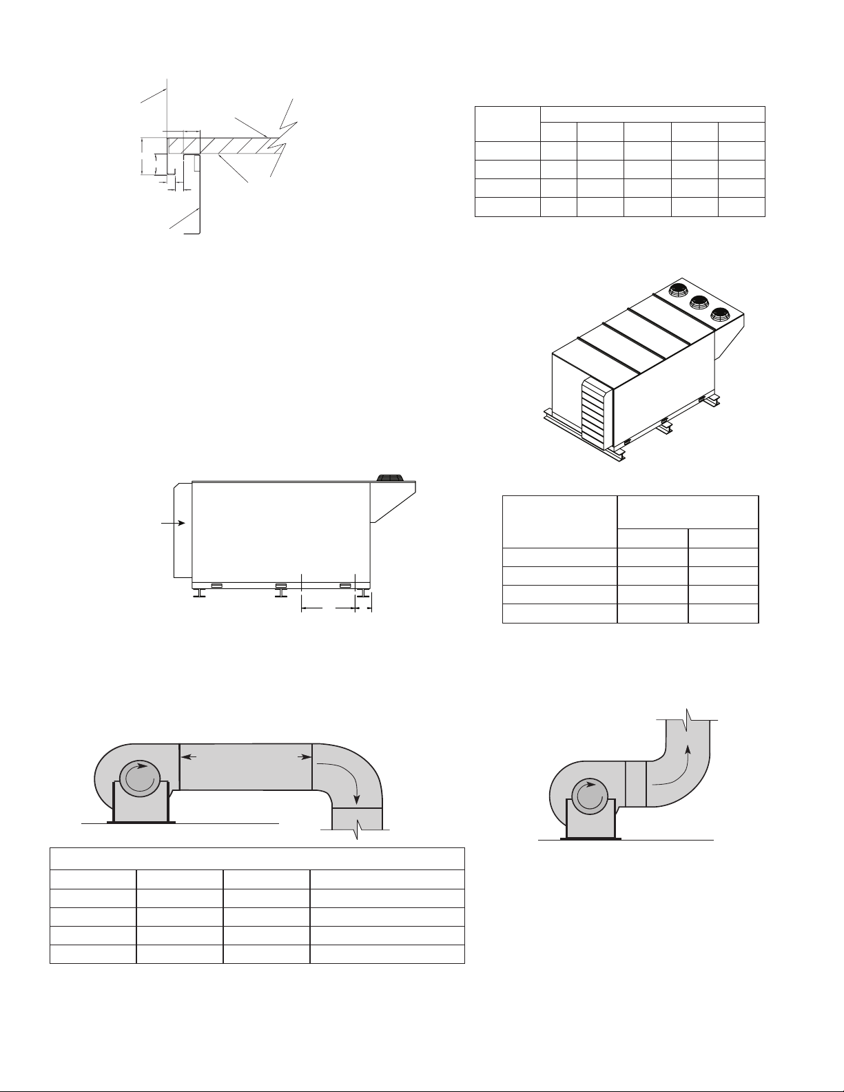
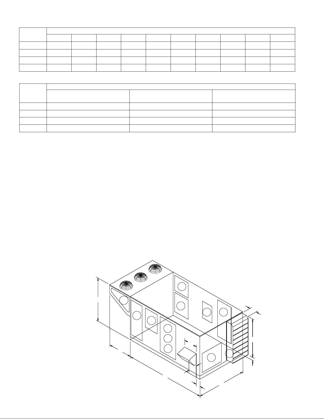
UNIT WEIGHTS & RECOMMENDED ROOF OPENING
Unit
Size
ERCH-20 2150 46 46
ERCH-45 3500 54 48
ERCH-55 4450 65 58
ERCH-90 6200 85 63
Unit weights assume rooftop configuration with weatherhoods, filters,
outdoor air damper, six row DX coil, integral condensing section and
an indirect gas fired furnace.
Approximate
Weight (lbs)
U
(inches)V (inches)
Lift using lifting lugs
and spreader bar
V
EXHAUST
INTAKE
SUPPLY
DISCHARGE
1/2 inch
U
1/2 inch
Position the unit roof opening such that the supply discharge and exhaust inlet of the unit will line up with the
corresponding ductwork. Be sure to allow for the recommended service clearances when positioning opening
(see Service Clearances). Do not face the outdoor air intake of the unit into prevailing wind and keep the intake
away from any other exhaust fans. Likewise, position the exhaust discharge opening away from outdoor air
intakes of any other equipment.
4
Page 5
Energy Recovery Unit with Packaged DX
INSTALLATION CONCERNS
Unobstructed airflow to the condensing section must be maintained at all times to ensure proper operating
efficiency and capacity of the cooling system. Unit placement should allow proper airflow over the condensing
section. The unit may not operate properly and damage may occur to the system if there is coil starvation (lack of
air over condenser) or warm air recirculating back through the condensing coil. Recirculating air is caused when
the unit is placed near obstacles that can redirect exhaust air from the condensing fans, back around to the coil
inlet. Overhangs or walls near the condensing section are two examples.
Another consideration when placing the unit is prevailing wind direction. The condensing coil operation can be
significantly affected when winds are blowing continuously and directly at the condensing coil. On hot days, the
wind will help the system by providing extra flow over the coil. But on cooler days, that same wind may overcool
the refrigerant, and cause hot gas bypass to operate more frequently, causing higher operating costs. Therefore,
avoiding direct winds will provide a more stable operation of the system throughout the cooling season.
Lack of air over the coil can reduce efficiencies and affect system operation. Do not allow debris (such as leaves
and trash), to accumulate on or near the unit. Keeping debris clear of the unit will ensure minimal obstruction to
the coils, keeping efficiencies and operation closer to design. The unit typically should not operate when snow
is present. In the event this is possible, make sure all snow is clear of the coil and condensing fans prior to
operating the unit.
If more than one unit is being installed, make provisions so discharge air from either the condensing fans or
exhaust fan of the unit do not discharge towards another unit’s intake. Also, OA intake and condensing sections
should be spaced as too allow proper airflow to each unit helping ensure the units operate as intended.
When cutting only duct openings, cut opening 1 inch (25mm) larger than duct size to allow clearance for
installation. Area enclosed by roof curb must comply with clearance to combustible materials. If the roof is
constructed of combustible materials, area within the roof curb must be ventilated, left open, or covered with
non-combustible material which has an “R” value of at least 5. If area within curb is open, higher radiated sound
levels may result.
Where the supply or warm air duct passes thru a combustible roof, a clearance of one inch must be maintained
between the outside edges of the duct and combustible material in accordance with NFPA Standard 90A.
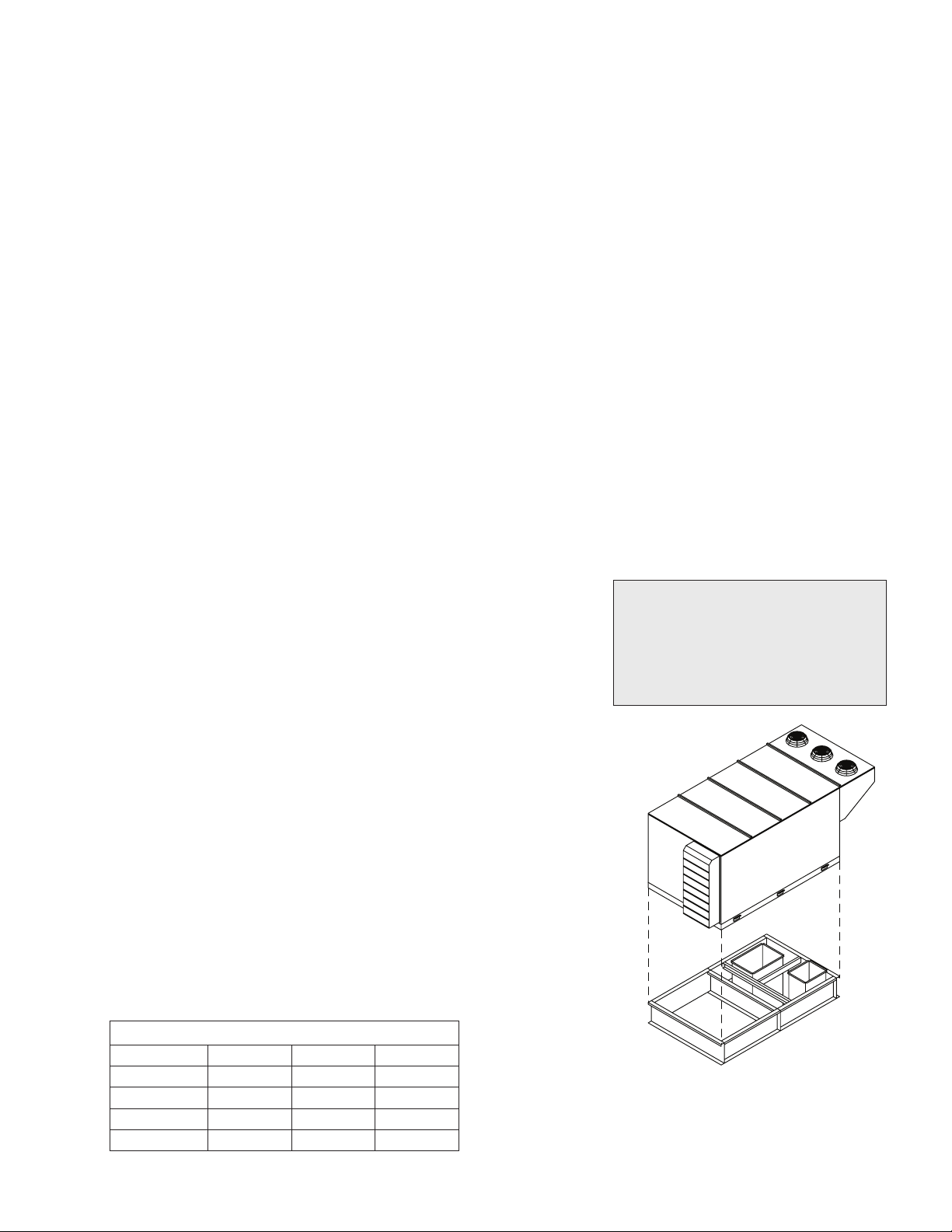
ROOF CURB MOUNTING
Rooftop units require curbs to be mounted first. The duct
connections must be located so they will be clear of structural
members of the building.
1. Factory Supplied Roof Curbs
Roof curbs are Model GKD, which are shipped in a knockdown
kit (includes duct adapter) and require field assembly (by others).
Assembly instructions are included with the curb.
2. Install Curb
Locate curb over roof opening and fasten in place. (Refer
to Recommended Roof Openings). Check that the diagonal
dimensions are within ±1/8 inch of each other and adjust as
necessary. For proper coil drainage and unit operation, it is
important that the installation be level. Shim as required to level.
3. Install Ductwork
Installation of all ducts should be done in accordance with
SMACNA and AMCA guidelines. Duct adapter provided to support
ducts prior to setting the unit.
4. Set the Unit
Lift unit to a point directly above the curb and duct openings.
Guide unit while lowering to align with duct openings. Roof curbs
fit inside the unit base. Make sure the unit is properly seated on
the curb and is level.
Roof curb details, including
duct location dimensions, are
available on ERCH roof curb
assembly instructions,
Part #468280.
Curb Outside Dimensions and Curb Weights (lbs)
Model L W Weight
ERCH-20 104.88 51 310
ERCH-45 115.75 60.63 400
ERCH-55 129.88 71.5 510
ERCH-90 148.13 90.75 720
All dimensions shown are in inches. Weights are for 12 inch high curbs.
Curb Outside Dimensions
5
Page 6
R
o
t
a
t
i
o
n
R
o
t
a
t
i
o
n
R
o
t
a
t
i
o
n
R
o
t
a
t
i
o
n
Length of Straight Duct
GOOD
POOR
GOODPOOR
Tu rning
Vanes
R
o
t
a
t
i
o
n
R
o
t
a
t
i
o
n
GOODPOOR
Tu rning
Vanes
ROOF CURB MOUNTING - CONTINUED
SIDE OF UNIT
BASE
A
B
C
D
E
1 INCH INSULATION
ERCH-20 2.00 2.00 1.00 0.88 0.75
ERCH-45 2.00 4.25 2.00 1.31 0.50
ERCH-55 2.00 4.25 2.00 1.31 0.50
ERCH-90 2.00 4.25 2.00 1.31 0.50
ROOF CURB
All dimensions shown are in inches.
Curb Cap Details for Factory Supplied Roof Curbs
RAIL MOUNTING
Rail Layout
• RailsdesignedtohandletheweightoftheERCHshouldbe
positioned as shown on the diagram (rails by others).
• Makesurethatrailpositioningdoesnotinterferewiththesupply
air discharge opening or the exhaust air intake opening on the
ERCH unit. (Avoid area dimensioned “B” below).
• Railsshouldrunthewidthoftheunitandextendbeyondtheunit
a minimum of 12 inches on each side.
• Setunitonrails.
Model
Energy Recovery Unit with Packaged DX
Curb Cap Dimensions
A B C D E
Isometric view of unit on rails
Rail
OUTDOOR AIR
INTAKE HOOD
Model
Mounting
A B
SUPPLY/EXHAUST
OPENING
B A
Side view of unit on rails
DUCTWORK CONNECTIONS
Examples of good and poor fan-to-duct connections are shown below. Airflow out of the fan should be directed
ERCH-20 5.00 41.00
ERCH-45 7.00 41.90
ERCH-55 5.50 53.00
ERCH-90 6.00 59.00
All dimensions shown are in inches.
straight or curve the same direction as the fan wheel rotates. Poor duct installation will result in low airflow and
other system effects.
n
o
i
Recommended Discharge Duct Size and Length
Model Blower Size Duct Size Straight Duct Length
ERCH-20 9 14 x 14 36
ERCH-45 12 20 x 20 48
ERCH-55 15 28 x 28 60
ERCH-90 18 32 x 32 60
All dimensions shown are in inches.
• Recommendedductsizesarebasedonvelocitiesacrossthecfmrangeofeachmodelatapproximately800feetperminute(FPM)at
minimum airflow and up to 1600 fpm at maximum airflow. Recommended duct sizes are only intended to be a guide and may not satisfy
the requirements of the project. Refer to plans for appropriate job specific duct size and/or velocity limitations.
• Straightductlengthswerecalculatedbasedon100%effectiveductlengthrequirementsasprescribedinAMCAPublication201.
Calculated values have been rounded up to nearest foot.
6
t
a
t
o
R
POOR
Page 7
Energy Recovery Unit with Packaged DX
OUTDOOR AIR WEATHERHOOD
Outdoor air weatherhood will be factory mounted.
EXHAUST WEATHERHOOD
The exhaust weatherhood is shipped separately as a kit with its own instructions.
DAMPERS
Backdraft dampers are always included as an integral part of the exhaust hood
assemblies. Motorized outdoor air and exhaust air dampers are optional and are
factory mounted (and wired) at the intake.
ELECTRICAL INFORMATION
The unit must be electrically grounded in accordance with the current National Electrical Code, ANSI/NFPA 70.
In Canada, use current CSA Standard C22.1, Canadian Electrical Code, Part 1. In addition, the installer should
be aware of any local ordinances or electrical company requirements that might apply. System power wiring
must be properly fused and conform to the local and national electrical codes. System power wiring is to the
unit main disconnect (door interlocking disconnect switch standard on most units) or distribution block and
must be compatible with the ratings on the nameplate: supply power voltage, phase, and amperage (Minimum
Circuit Amps - MCA, Maximum Overcurrent Protection - MOP). All wiring beyond this point has been done by
the manufacturer and cannot be modified without affecting the unit’s agency / safety certification.
If field installing an additional disconnect switch, it is recommended that there is at least four feet of service
room between the switch and system access panels. When providing or replacing fuses in a fusible disconnect,
use dual element time delay fuses and size according to the rating plate.
Field Power Connection: Electronic wiring is run through the roof of the unit. All power and control
connections should be run through the floor or side panel.
If power supply is desired through bottom of unit, run the wiring through the curb, cut a hole in the cabinet
bottom, and wire to the disconnect switch. Seal penetration in cabinet bottom to prevent leakage.
The electric supply to the unit must meet stringent requirements for the system to operate properly. Voltage
supply and voltage imbalance between phases should be within the following tolerances. If the power is not
within these voltage tolerances, contact the power company prior to operating the system.
Voltage Supply - See voltage use range on the rating plate. Measure and record each supply leg voltage at all
line disconnect switches. Readings must fall within the allowable range on the rating plate.
Voltage Imbalance - In a 3-phase system, excessive voltage imbalance between phases will cause motors
to overheat and eventually fail. Maximum allowable imbalance is 2%. To determine voltage imbalance, use
recorded voltage measurements in this formula.
Key: V1, V2, V3 = line voltages as measured
VA (average) = (V1 + V2 + V3) / 3
VD = Line voltage (V1, V2 or V3) that deviates farthest from average (VA)
Formula: % Voltage Imbalance = [100 x (VA-VD)] / VA
CAUTION
If any of the original wire as supplied with the appliance must be replaced, it must be
replaced with wiring material having a temperature rating of at least 105ºC.
WARNING
To prevent injury or death due to electrocution or
contact with moving parts, lock disconnect switch
open.
Most factory supplied electrical components are pre-wired. To
determine what electrical accessories require additional field wiring,
refer to the unit specific wiring diagram located on the inside of the
unit control center access door. The low voltage control circuit is
24 Vac and control wiring should not exceed 0.75 ohms. Refer to
Field Control Wiring Length/Gauge table for wire length maximums
for a given wire gauge. Control wires should not be run inside the
same conduit as that carrying the supply power. Make sure that field supplied conduit does not interfere with
access panel operation.
For units with a gas furnace, if you turn off the
power supply, turn off the gas.
WARNING
Field Control Wiring Length/Gauge
Total Wire Length Minimum Wire Gauge
125 ft. 18
200 ft. 16
300 ft. 14
450 ft. 12
7
Page 8
Energy Recovery Unit with Packaged DX
If wire resistance exceeds 0.75 ohms, an industrial-style, plug-in relay should be added to the unit control
center and wired in place of the remote switch (typically between terminal blocks R and G on the terminal strip
(refer to Typical Control Center Components). The relay must be rated for at least 5 amps and have a 24 Vac
coil. Failure to comply with these guidelines may cause motor starters to “chatter” or not pull in which can
cause contactor failures and/or motor failures.
Note: Standard factory installed electric post-heaters have their own disconnect separate from the unit
disconnect. Thus, each electric post-heater requires its own separate power connection.
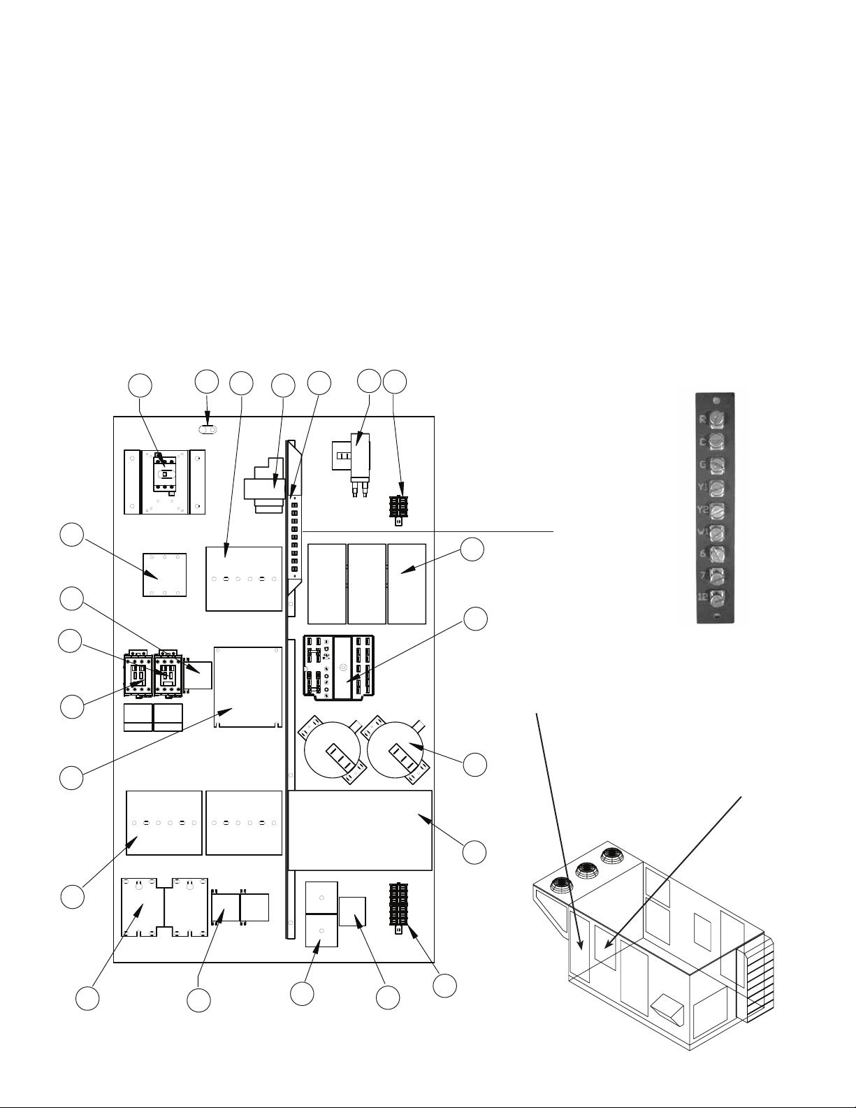
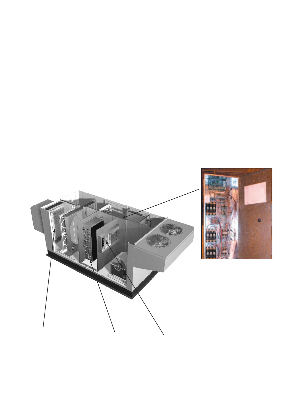
CONTROL CENTER COMPONENTS
1. Main Disconnect (non-fusible,
lockable)
2. Motor Starter - Exhaust Air Fan
3. Motor Starter - Outdoor Air Fan
4. Motor Contactor - Energy Wheel
5. 24 Vac Control Transformer
6. 24 Vac Terminal strip
7. Fuses for blower motors
8. Grounding lug
9. Distributor block
10. Compressor fuse blocks
11. Compressor contactors
12. Condensing fan contactors
13. Compressor cycle timers
14. Compressor relay
15. Terminal block
Optional Control Center Components
16. DDC controller
17. Dirty filter pressure switches
18. Economizer module
19. Thermostats for:
- Economizer module
- Energy Recovery wheel frost
control
- Compressor lock out
20. Terminal block
21. Frost control pressure switch
22. Energy recovery wheel VFD
3
22
8
1 5
7
9
6
21
20
Component #6
19
Exploded Detail
of Terminal Strip
4
18
Refer to “Refrigeration
System” section for
components in compressor
2
compartment
Access to Control Center
17
Components is gained through
the access panel indicated.
16
10
11
12
13
14
15
8
Page 9
Energy Recovery Unit with Packaged DX
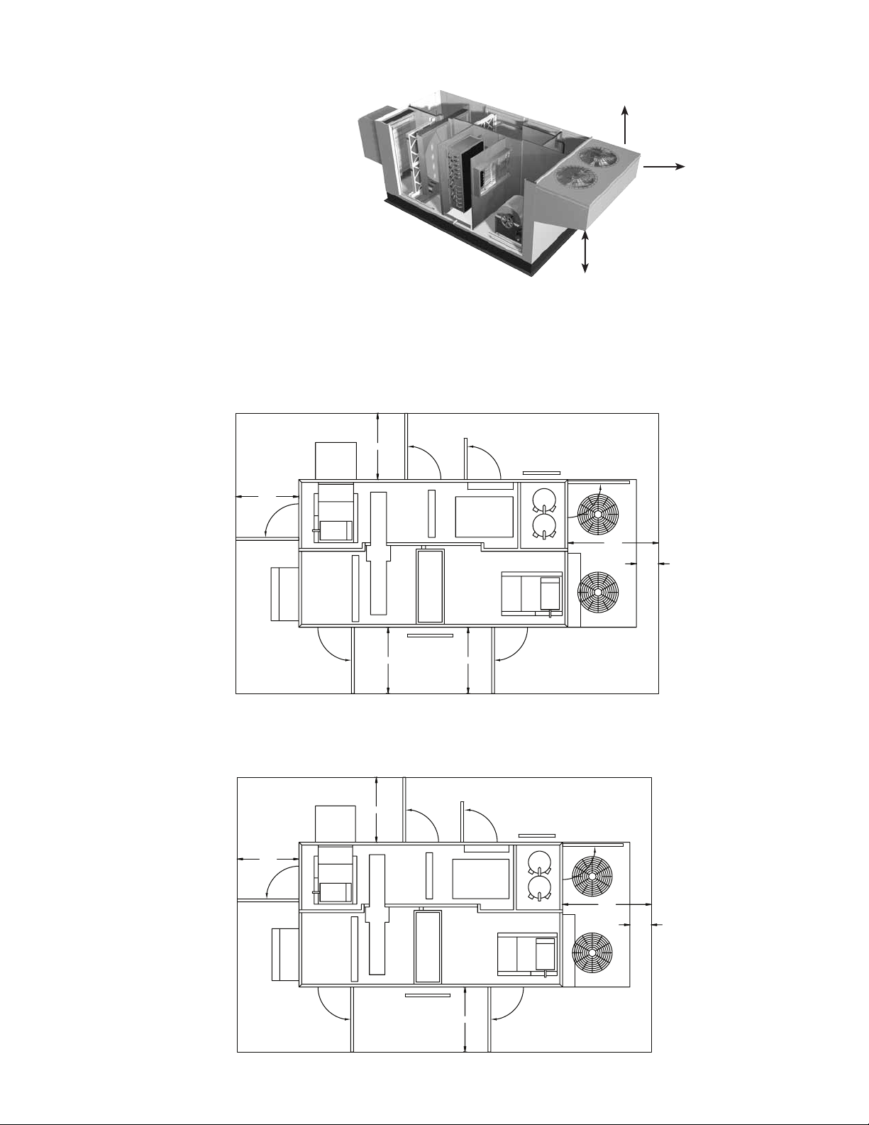
SERVICE CLEARANCES / ACCESS PANEL LOCATIONS FOR MODEL ERCH
Clearances must be maintained on all
sides of this unit. This especially is true
with the top of this unit. Hot air is being
discharged through the condensing
fans during operation, and the more
clearance available, the better the
chance of avoiding recirculation or coil
starvation. This unit should never be
placed under an overhang or inside a
building. A minimum of 48 inches over
the condensing fans is recommended.
ERCH-20, 45, 55, and 90 units require
minimum clearances for access on all sides for routine maintenance. Filter replacement, drain pan inspection
and cleaning, energy wheel cassette inspection, fan bearing lubrication and belt adjustment are examples of
routine maintenance that must be performed. Blower and motor assemblies, energy recovery wheel cassette,
coil and filter sections are always provided with a service door or panel for proper component access.
Clearances for component removal may be greater than the service clearances, refer to drawings for these
dimensions.
ERCH-20
ERCH-45
36 IN
ACCESS PANEL
EXHAUST
HOOD
HOOD
OUTDOOR AIR
FILTERS
36 IN
WHEEL CASSETTE
ACCESS PANEL
FILTERS
COIL
SECTION
ACCESS PANEL
ELECTRICAL BOX
EXHAUST AIR
INTAKE
ACCESS PANEL
ACCESS PANEL
IG HEATER
Minimum 48 inches
clearance
Minimum 12 inches
clearance
Condensing Coil Intake
Keep this area clear
52 IN
CLEARANCE
WITH IG HEATER
12 IN
MINIMUM
ERCH-55
ERCH-90
ACCESS PANEL
*48 IN
ACCESS PANEL
**64 IN
ACCESS PANEL
Clearances for service and component removal on ERCH-20 and ERCH-45
* Clearance for energy wheel removal on ERCH-20
** Clearance for energy wheel removal on ERCH-45
FILTERS
42 IN
ACCESS PANEL
ACCESS PANEL
WHEEL CASSETTE
FILTERS
COIL
SECTION
ACCESS PANEL
ACCESS PANEL
ELECTRICAL BOX
EXHAUST AIR
INTAKE
42 IN
ACCESS PANEL
ACCESS PANEL
ACCESS PANEL
WITH IG HEATER
IG HEATER
52 IN
CLEARANCE
42 IN
ACCESS PANEL
EXHAUST
HOOD
HOOD
OUTDOOR AIR
12 IN
MINIMUM
Clearances for service and component removal on ERCH-55 and ERCH-90
9
Page 10
Energy Recovery Unit with Packaged DX
A
J
E
B
H
C
I
G
F
D
DIMENSIONAL DATA / ACCESS DOOR DESCRIPTIONS AND LOCATIONS
Model
A B C D E F G H I J
Exterior Dimensions
ERCH-20 108 50 56 27 28.5 17 6 14.25 18 18
ERCH-45 119 69 66 38 41 23.375 10.5 13.375 20 16
ERCH-55 133.5 70 76 39 59.5 5.875 7.125 21.25 25 16
ERCH-90 151.5 85 96 46 78 2.875 10 24.5 27 16
All dimensions shown are in inches.
Overall Exterior Dimensions
Model
(including Lifting Lugs)
Width
Overall Width
(with Exhaust Hood)
Overall Length
(with Outdoor Air Hood)
ERCH-20 59.5 75 116
ERCH-45 69.5 86 122
ERCH-55 79.5 101 134
ERCH-90 99.5 123 147
All dimensions shown are in inches.
Following is a list of items accessible through the access doors shown on the diagrams. Some items are
optional and may not have been provided.
1. Exhaust blower, motor, and drives
2. Aluminum mesh filters (intake hood)
3. Energy recovery wheel, motor, belt, and seals
Outdoor air filters
Outdoor air intake damper (optional)
Electric preheater (optional)
Frost control sensors (optional)
Economizer sensors (optional)
4. Coil access / Drain pan
5a. Outdoor air blower, motor, and drives
(with indirect gas furnace)
6. Control center
All electrical controls
VFD for energy recovery wheel (optional)
7. Exhaust air filters
Exhaust air intake damper (optional)
8. Electric post-heater control center (optional)
9. Bypass damper (optional)
10. Condensing fan motors
11. Compressor(s) - refer to Refrigeration System
section for components in compressor
compartment
Drain Pan
5b. Outdoor air blower, motor, and drives
(without indirect gas furnace)
Coil access / Drain pan (w/o Electric Heat)
Model ERCH with Packaged DX
10
5a
10
5b
11
6
7
8
9
4
3
1
2
Page 11
Energy Recovery Unit with Packaged DX
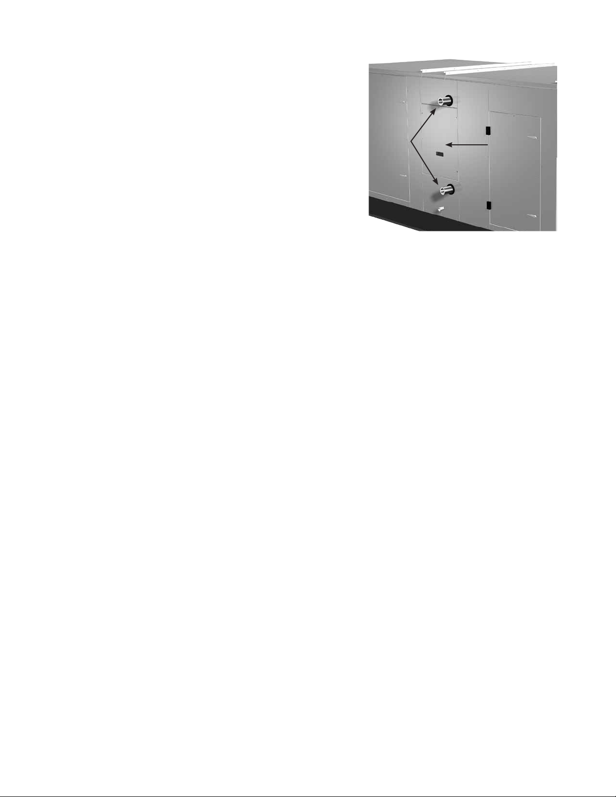
COIL APPLICATION RECOMMENDATIONS
Factory installed cooling and heating components are mounted
in the coil section of the unit. The coil section is downstream
of the energy wheel on the supply air side of the unit.
Note the coil connection locations on the picture. Coil
connections are located external to the unit as shown. Coil
connections that are not external have been ordered from the
factory with interior or exhaust airstream coil connections.
Hot
water coil
connections
Coil access door
Note: DX coil liquid connection is internal to units.
WATER COILS
1. Piping should be in accordance with accepted industry
standards. Pipework should be supported independently
of the coils. Water connections are male NPT iron pipe.
When installing couplings, do not apply undue stress to the
connection extending through the unit. Use a backup pipe wrench to avoid breaking the weld between coil
connection and header.
2. Connect the WATER SUPPLY TO THE BOTTOM CONNECTION on the air leaving side and the WATER
RETURN TO THE TOP CONNECTION on the air entering side. To insure proper venting, an external air vent
in the piping is recommended. Connecting the supply and/or return in any other manner will result in very
poor performance. Be sure to replace factory installed grommets around coil connections if removed for
piping. Failure to replace grommets will result in water leakage into the unit and altered performance.
3. The air vent at the uppermost point should be temporarily opened during system start-up to release all of the
air from the coil. To maintain heat transfer capacity, periodically vent any air in coil.
4. Water coils are not normally recommended for use with entering air temperatures below 40ºF; however,
the energy recovery wheel maintains a pre-coil temperature higher than 40ºF. No control system can be
depended on to be 100% safe against freeze-up with water coils. Glycol solutions or brines are the only safe
media for operation of water coils with low entering air conditions.
CONTINUOUS WATER CIRCULATION THROUGH THE COIL AT ALL TIMES IS HIGHLY RECOMMENDED.
5. Pipe sizes for the system must be selected on the basis of the head (pressure) available from the circulation
pump. The velocity should not exceed 6 feet per second and the friction loss should be approximately 3 feet
of water column per 100 feet of pipe.
DIRECT EXPANSION (DX) COILS WITH INTEGRAL CONDENSING SECTION
1. The condensate drain pipe should be sized adequately to ensure the condensate drains properly. Refer to
Drain Trap section.
11
Page 12
Energy Recovery Unit with Packaged DX
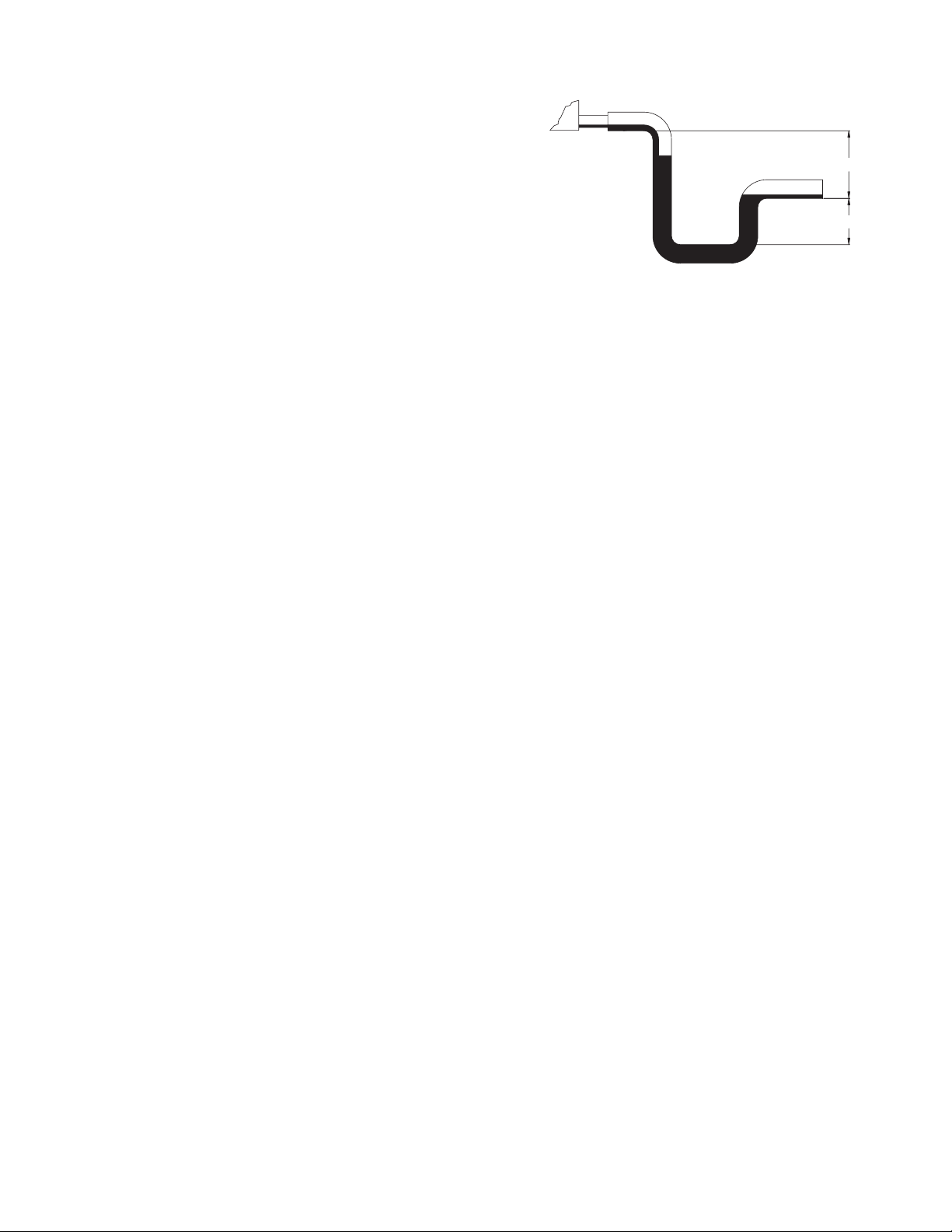
DRAIN TRAP
Cooling coils are provided with a stainless steel drain pan
with 1-inch male NPT drain connection. A drain trap must be
connected to the drain connection to allow excess water to
flow out of the drain pan. More importantly, though, due to the
negative internal static of the cooling coil compartment, installing
the drain trap prevents outdoor air from being pulled into the
drain pan and consequently forcing water out of the pan and into
the unit.
To ensure the drain trap works properly, the trap height must
account for the difference in static pressure between ambient
conditions outside the unit and the internal negative pressure of the cooling coil compartment. For energy
recovery units, an assumption of 3.0 in. wg differential will be sufficient. This would require a trap design as
shown. If the internal static is believed to be higher, consult factory.
Refer to local codes to determine drainage requirements. If draining onto to roof, place a drip pad below drain
to protect roof. If draining onto roof is not acceptable, a drain line must be attached to the trap. The drain line
must be pitched away from the unit at least 1/8-in. per foot. On longer runs, an air break should be used to
ensure proper drainage. Local codes may require drainage into a waste water system.
Drainage problems not only occur from improper drain trap design, but also from lack of maintenance of the
cooling coil compartment. Algae can form in the drain pan and trap and cause reduced water flow, which can in
turn result in backup into the system. Regular maintenance will prevent this from occurring. If the drains have a
cleanout opening, be sure to close the opening after cleaning.
4 in.
2 in.
12
Page 13
Energy Recovery Unit with Packaged DX
OPTIONAL ACCESSORIES
Electric Heater Application/Operation
Factory installed electric heaters can be provided for preheat and/or post-heat. An electric preheater warms
the outdoor air prior to the energy recovery wheel to prevent frosting on the wheel. An electric post-heater
warms the air leaving the energy recovery wheel to a user specified discharge temperature. Electric heaters are
available in 208, 230, or 460 Vac (refer to heater nameplate for voltage).
Preheaters: Preheaters are standard as 2-stage, step control. Step control heaters are designed with
multiple stages made up of equal increments of heating capability. For example, a 10 kW
heater with two stages will be composed of two 5-kW stages. Preheaters are single point
wired at the factory. A temperature sensor (with field adjustable set point) is mounted in the
outdoor airstream after the preheater to turn the preheater on. See Frost Control Application
/Operation for typical set points. If the temperature falls below the set point and the wheel
pressure drop sensor is triggered, the first stage of the preheater will turn on. If the first stage
does not satisfy the set point, the second stage will also turn on.
Post-heaters: Post-heaters are standard as SCR control. Post-heaters are not single point wired (see
Electrical Connections). A temperature sensor (with field adjustable set point) is mounted in
the outdoor airstream after the post-heater to turn the post-heater on. A SCR heater provides
an infinitely modulating control of the heat to provide an accurate discharge temperature. A
call for heat is required.
Electric Preheater
The pre-heater is single
point wired to the ERCH
control center. Access
to the preheater control
panel is through the
supply filter door.
DX
Cooling Coil
Post-Heater Control Panel
The post-heater is not single point
wired to the ERCH control center.
Separate power must be supplied to
the post-heater disconnect (located
in unit control center).
See ’Access Door Descriptions and
Locations’ for access to post-heater
control panel. For Model ERCH, the
exhaust filters must be removed
from the unit to access.
Electric
Post-Heater
13
Page 14
Energy Recovery Unit with Packaged DX
OPTIONAL ACCESSORIES
Frost Control Application/Operation
Extremely cold outdoor air temperatures can cause moisture condensation and frosting on the energy recovery
wheel. Frost control is an optional feature that will prevent/control wheel frosting. Three options are available:
1) Timed Exhaust frost control
2) Electric preheat frost control
3) Modulating wheel frost control
All of these options are provided with a thermostat (with
probe) mounted in the outdoor air intake compartment and
a pressure sensor to monitor pressure drop across the
wheel. The typical temperature setting corresponds to the
indoor air relative humidity as shown in the Frost Threshold Temperatures Table and represents when frost can
occur. An increase in pressure drop would indicate that frost is occurring. Both the pressure sensor AND the
outdoor air temperature sensor must trigger in order to initiate frost control. The two sensors together ensure
that frost control is only initiated during a real frost condition. Field wiring of a light (or other alarm) between
6 & C in the control center will notify personnel when unit is in frost control mode (refer to Remote Panel Wiring
schematics section for wiring details). The following explains the three options in more detail.
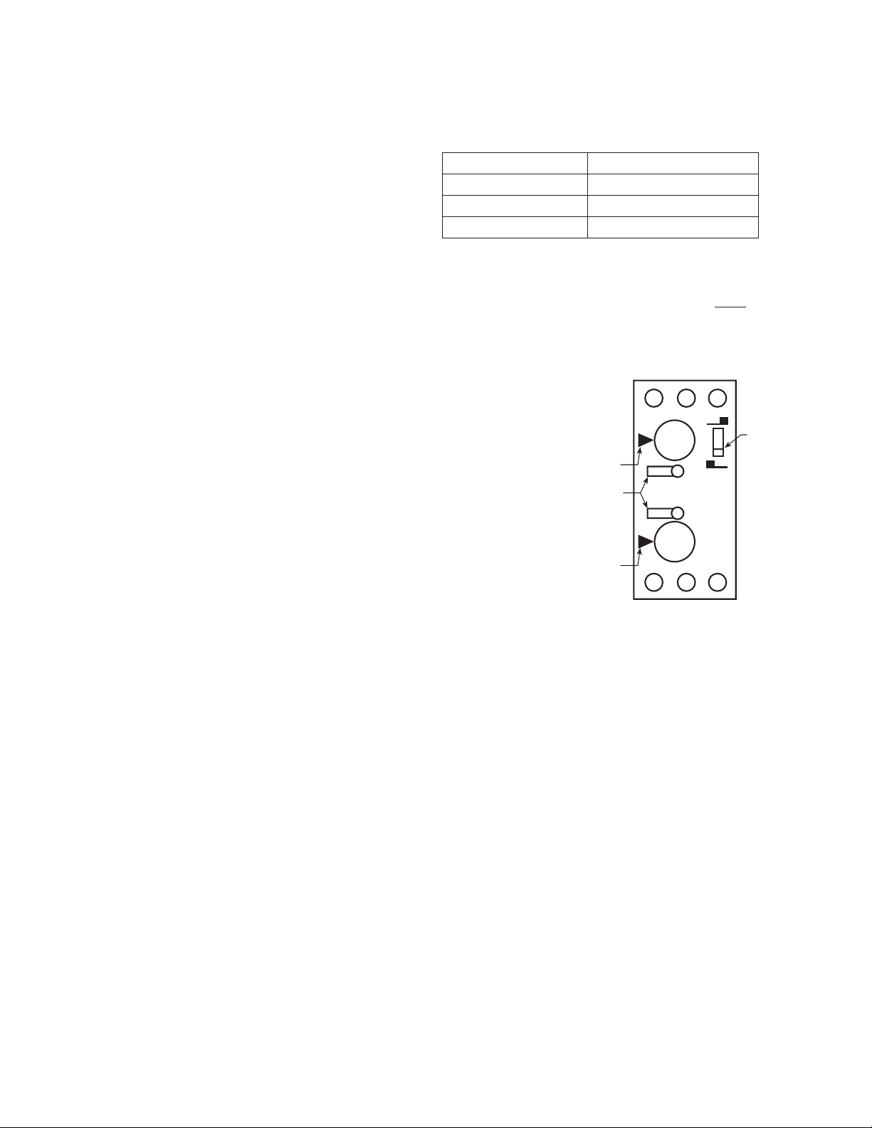
Timed exhaust frost control includes a timer in addition to the thermostat and
wheel pressure sensor. When timed exhaust frost control is initiated, the timer
will turn the supply blower on and off to allow the warm exhaust air to defrost
the energy recovery wheel. Default factory settings are 5 minutes off and 30
minutes on. Use the following test procedure for troubleshooting.
Testing (refer to diagram at right)
• Jumperthewheelpressureswitchintheunitcontrolcenter.Setthe
Timer Scale for T1 and T2 to 1 minute. Set the Timer Settings for T1 and
T2 to 1.0. Set the dip switch to the down position. (normal position)
• Turnthetemperaturesensorupashighaspossible.Thesupplyblower
should cycle on for one minute, then turn off for one minute.
• Aftertesting,settheTimer Scale as follows: T1 = 10 minutes, T2 =
1 hour
• SettheTimer Settings as follows: T1 = 0.5, T2 = 0.5. The timer is now
set for 5 minutes off and 30 minutes on. Remember to remove the jumper.
Electric preheat frost control includes an electric heater (at outdoor air intake) and an airflow pressure switch
(located at the preheater) in addition to the thermostat and pressure sensor on wheel. (Refer to Electric Heater
Application/Operation for electric preheater location). When electric preheat frost control is initiated, the electric
preheater will turn on and warm the air entering the energy wheel to avoid frosting. Use the following test
procedure for troubleshooting.
Testing
• Turnthethermostatashighasitwillgoandjumperthewheelpressuresensor.Theheater
should turn on.
• Ifitdoesn’t,eitherputtheoutdoorairsidedoorsonortemporarilyjumpertheairflowpressure
switch in the preheater control center to avoid nuisance tripping of the pressure switch. Also
check the airflow switch pressure tap located at the supply discharge blower to ensure the
tubing is connected and the tap is not blocked. Remember to remove the jumpers.
Modulating wheel frost control includes a variable frequency drive in addition to the thermostat and pressure
sensor. When modulating wheel frost control is initiated, the variable frequency drive will reduce the speed
of the wheel. Reducing the speed of the energy wheel reduces its effectiveness, which keeps the exhaust air
condition from reaching saturation, thus, eliminating condensation and frosting. If the outdoor air temperature is
greater than the frost threshold temperature OR the pressure differential is less than the set point, the wheel will
run at full speed. If the outdoor air temperature is less than the frost threshold temperature AND the pressure
differential is greater than the set point, the wheel will run at reduced speed until the pressure differential falls
below the set point. The temperature and pressure differential set points are set at the factory, but are fieldadjustable (refer to VFD section for more information). The variable frequency drive will be fully programmed at
the factory.
14
Indoor RH @ 70°F Frost Threshold Temp
20% -10º F
30% -5º F
40% 0º F
Frost Threshold Temperatures
A1 B1 15
0.60.8
0.41.0
T2
Timer
Scale
T1
0.20
T21 MIN
T11 MIN
0.60.8
0.41.0
0.20
16 18 A2
Timer
Dip
Switch
Page 15
Energy Recovery Unit with Packaged DX
OPTIONAL ACCESSORIES
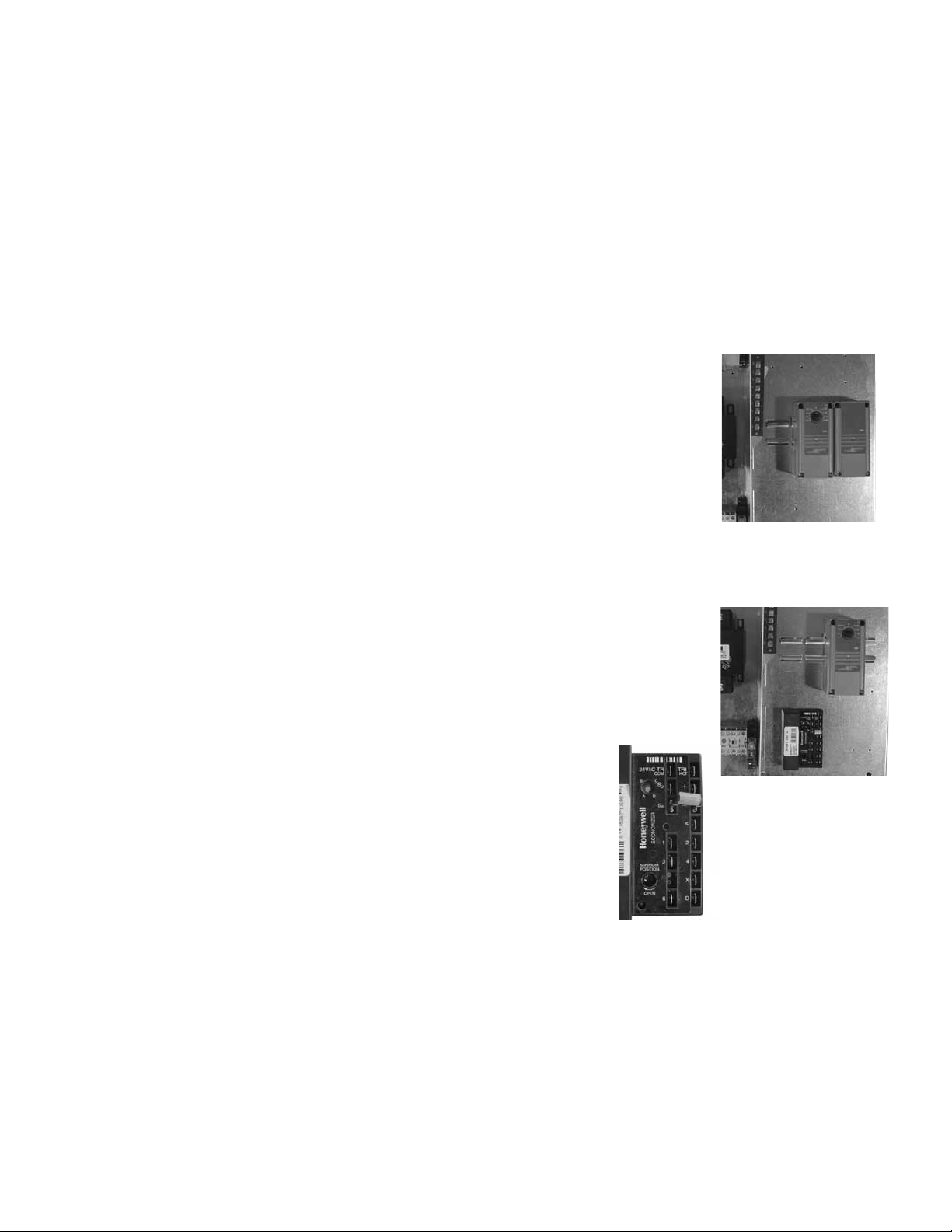
Economizer Application/Operation
The energy recovery wheel operation can be altered to take advantage of economizer operation (free cooling).
Two modes are available: 1) De-energizing the wheel or 2) Modulating the wheel. A field supplied call for cool
(Y1) is required.
De-energizing the wheel is accomplished with a signal from a Temperature or Enthalpy sensor mounted
in the air intake compartment. This Primary sensor will de-energize the energy wheel when the outdoor air
temperature (factory default is 65ºF) or enthalpy (factory default is the ‘D’ setting) is below the field adjustable
set point. An Override temperature sensor is also furnished in the outdoor air intake compartment to deactivate
economizer mode. The Override (with field adjustable set point) is set at some temperature lower than the
Primary sensor (factory default is 50ºF). Effectively, the two sensors create a deadband where the energy
recovery wheel will not operate and free cooling from outside can be brought into the building unconditioned.
Testing
Temperature Sensor with Override
• TurnbothTemperatureandOverridethermostatsdownaslowastheygo.The
wheel should be rotating.
• TurntheTemperaturesensorupashighasitgoes,andkeeptheOverride
sensor as low as it will go. The wheel should stop rotating.
• Turnbothsensorsashighastheywillgo.Thewheelshouldstartrotating.
• SettheTemperaturesensoratdesiredpointforeconomizeroperationtobegin.
Set the Override sensor at desired point for economizer operation to end
(factory default is 65ºF and 50ºF, respectively).
Enthalpy Sensor with Override
• Turnunitpoweroff.DisconnectC7400solidstateenthalpysensorfromterminal
So on the enthalpy controller. Also, disconnect the 620 ohm resistor from
terminal Sr on the enthalpy controller. Turn unit power on. The LED on the
enthalpy controller should light and the energy recovery wheel should not rotate.
• Turnunitpoweroff.Reconnect620ohmresistortoterminalSrontheenthalpy
controller. Turn unit power on. The LED on the enthalpy controller should not
light and the energy recovery wheel should energize and rotate.
If the steps above provide the results described, the enthalpy economizer is
working properly.
• Turnunitpoweroff.ReconnectC7400solidstateenthalpysensor
to terminal So.
Temperature Sensor
with Override
Enthalpy Sensor
with Override
Modulating the Wheel
In applications in which an internal heat gain is present in the space,
the rotational speed of the energy wheel may be modulated (via
variable frequency drive) to avoid overheating the space during the
Enthalpy
Controller
winter. The speed of the energy wheel will be controlled in response to
the discharge temperature set point.
Sequence of Operation:
The variable frequency drive is fully programmed at the factory (refer to VFD section
for more information). A “call for cool” must be field wired to the unit (terminals provided in unit - refer to wiring
diagram in unit control center) to allow for initiation of economizer mode. When the space calls for cooling,
factory supplied controls will drive the following wheel operations:
TOA > T
RA
TOA < TRA and TOA > T
TOA < TRA and TOA < T
: Wheel runs at full speed (maximum energy recovery)
: Wheel is stopped (no energy recovery)
SA
: Wheel will modulate to maintain discharge temperature
SA
where (TOA) is the outdoor air temperature set point, (TRA) is the return air temperature set point, and (TSA) is the
supply air discharge thermostat set point.
15
Page 16
Energy Recovery Unit with Packaged DX
OPTIONAL ACCESSORIES
Variable Frequency Drives for Energy Recovery Wheel
Factory installed VFD for the energy recovery wheel are programmed at the factory per the settings shown
below. Refer to the instruction manual that ships with the unit when making adjustments. A copy of the manual
can be found online at www.drives.com. For technical support, contact Yaskawa direct at 1-800-927-5292.
Yaskawa GPD-305 Drive
Parameter Setting
n01 Access Level 1
n30 Ref Upper Limit 100% or 66%*
n32 Motor Rated FLA Motor FLA
n33 Elect Thermal Overload 1
n36 Multi-Function input (terminal S2) 10
n40 Multi-Function output (MA,MB,MC) 4
n41 Analog Freq. Reference Gain 0
n42 Analog Freq. Reference Bias 99
n46 Carrier Frequency 2
n58 Frequency Detection Level 20
n01 Access Level 0
*36 inch wheel is 66% (40Hz). All other wheels are 100% (60Hz).
16
Page 17

Energy Recovery Unit with Packaged DX
6C
OPTIONAL ACCESSORIES
Wiring Diagram
Following is an example of a typical wiring diagram located in the unit control center. This wiring diagram
includes a legend highlighting which accessories were provided with the unit. Factory wiring and field wiring
are also indicated. This particular example includes 1) variable frequency drives on the blowers requiring a
modulating input, 2) modulating energy recovery wheel with factory controls for economizer, 3) energy recovery
wheel rotation sensor, 4) outdoor air and exhaust air dirty filter switches, 5) motorized outdoor air and exhaust
air intake dampers, and 6) timed exhaust frost control. Many other factory installed and wired accessories are
available.
MAIN POWER
TO UNIT
GROUND
CONDENSING FAN 2
CONDENSING FAN 1
COMPRESSOR 2
COMPRESSOR 1
R
S1
ST1
13 14
S6
S7
ST2-NO
CC1-NO
CC2-NO
DS1
L1
L2
L3
CF2
CF1
CC2
CC1
G
620 OHM RESISTOR OR
RETURN AIR SENSOR
OUTDOOR AIR
SENSOR
MIXED AIR
SENSOR
Y1
Y2
51
COM NC
DB1
CH1 CH2
T1
16
15
PS1
NO C COM NO
SR
TR1
EC
SR+
SO
+
SO+
T
T1
1
TR
3
TS6
52
FCS
55
FR
2-10V
-
FC
5
2
4
LPS HPS
56
ST1 O.L.
96 95
ST2 O.L.
96 95
TO MA AND MC
MA
ON VFD-W
MC
24 VAC
THERMOSTAT(S) TS1, TS6
TS1
TO FR AND FC
ON VFD-W
R7
1
R7
86
(LOCATED IN CONDENSING FAN)
(LOCATED IN CONDENSING FAN)
3
3
3
53
CF1 O.L.
1P1
1P2
CF2 O.L.
2P22P1
TR1
4
S2
R14
24
6
T6
1
T7
1
54
MULTI-VOLTAGE PRIMARY
24 SECONDARY
A2 A1
A2 A1
A2 A1
A2
OA-SENSOR
SENSOR
A1T1A2
CC2
2
A1A1A2
ST1
ST2
CC1
CF1
CF2
ST1
O.L.
LEGEND
EXHAUST FAN
O.L.
ST2
L1
L2
VFD-W
L3
S1
SC
R1
4
3
C
A1
COM
B1
7
A2
EXHAUST DAMPER
EXHAUST FAN
SUPPLY DAMPER
SUPPLY FAN
ENERGY WHEEL
ROTATION SENSOR
ROTATION SENSOR
THERMOSTAT CONTROLLER(S)
FROST CONTROL
ECONOMIZER CONTROL
COMPRESSOR 1
COMPRESSOR 2
COMPRESSOR INTERLOCKS
CONDENSING FAN 1
CONDENSING FAN 2
D1
D2
R1
R14
12
R7
MOTOR
SUPPLY FAN
MOTOR
T1
T2
ENERGY WHEEL
MCT3MA
FCFR
SEE BELOW FOR
TERMINAL CONNECTIONS
C1 COOLING STAGE 1 RELAY
C2 COOLING STAGE 2 RELAY
CC COMPRESSOR CONTACTOR
*
CF CONDENSING FAN CONTACTOR
*
CH COMPRESSOR SUMP HEATER
*
D DAMPER
**
DB POWER DISTRIBUTION BLOCK
*
DL DAMPER LIMIT SWITCH
DS DISCONNECT SWITCH
*
EC ECONOMIZER CONTROLLER
*
FCS CONDENSOR FAN CYCLE SWITCH
*
FU FUSES
FU5 CONTROL TRANSFORMER FUSES (NOT ON CLASS II)
FZ1 FREEZE PROTECTION
HG HOT GAS REHEAT VALVE
HPS HIGH PRESSURE SWITCH (MANUAL RESET)
*
LPS LOW PRESSURE SWITCH
*
PS1 WHEEL FROST PRESSURE SWITCH
*
PS2 SUPPLY DIRTY FILTER PRESSURE SWITCH
*
PS3 EXHAUST DIRTY FILTER PRESSURE SWITCH
*
R1 ENERGY WHEEL RELAY/CONTACTOR
*
R2 OCCUPIED/UNOCCUPIED RELAY
R3 EXHAUST BLOWER VFD RELAY
R4 SUPPLY BLOWER VFD RELAY
R5 MODULATING WHEEL FROST CONTROL RELAY
R6 ECONOMIZER RELAY
R7 COMPRESSOR INTERLOCK RELAY
*
R8 EVAP RELAY (INDIRECT)
R9 EVAP RELAY (DIRECT)
R10 UNIT RELAY
R11 POST HEAT RELAY
R12 DEHUMIDIFICATION RELAY
R13 ROOM CALL FOR HEAT RELAY
R14 ROTATION SENSOR RELAY
*
R15 ROTATION SENSOR RELAY
o
S1 FAN SWITCH
S2 ROTATION SENSOR (LOCATED BY WHEEL)
*
S3 ROTATION SENSOR (LOCATED BY WHEEL)
S4 CALL FOR HEAT SWITCH
S5 OCC/UNOCC SWITCH - CLOSED=OCCUPIED/OPEN=UNOCCUPIED
S6 CALL FOR COOL SWITCH (FIRST STAGE)
o
o
S7 CALL FOR COOL SWITCH (SECOND STAGE)
S8 CALL FOR DEHUMIDIFICATION SWITCH
ST MOTOR STARTER
*
*
T1 FROST CONTROL TIMER
*
TYPICAL SETTINGS t1(OFF) = 5 MIN., t2(ON) = 30 MIN.
T4 ECONOMIZER WHEEL JOG TIMER
TYPICAL SETTINGS t1(OFF) = 3 HRS., t2(ON) = 10 SEC.
T5 EVAP DELAY OFF TIMER
*
T6 COMPRESSOR MINIMUM OFF TIMER (TYP. 3 MIN.)
T7 COMPRESSOR MINIMUM OFF TIMER (TYP. 3 MIN.)
*
TR TRANSFORMER
*
TS1 FROST CONTROL THERMOSTAT (JUMPER - HEAT)
*
CLOSES ON TEMP. DECREASE TYPICAL SETTING 5° F.
TS2 ECONOMIZER LOW LIMIT THERMOSTAT (JUMPER - HEAT)
OPENS ON TEMP. DECREASE TYP. SETTING 20° OFFSET OR 50°F.
TS3 ECONOMIZER UPPER LIMIT THERMOSTAT (JUMPER - HEAT)
CLOSES ON TEMP. DECREASE TYP. SETTING 65° F./2° DIFF.
TS4 ROOM OVERRIDE SENSOR
TS5 INLET AIR POST HEATER LOCKOUT THERMOSTAT (AFTER WHEEL)
CLOSES ON TEMP. DECREASE TYPICAL SETTING 65° F.
TS6 INLET AIR COMPRESSOR LOCKOUT THERMOSTAT (JUMPER-HEAT )
*
OPENS ON TEMP. DECREASE TYPICAL SETTING 60° F./2° DIFF.
FACTORY SUPPLIED AND WIRED
*
o FIELD WIRED
FIELD CONTROL WIRING RESISTANCE SHOULD NOT EXCEED 0.75 OHM.
IF RESISTANCE EXCEEDS 0.75 OHM THEN CONSULT FACTORY.
USE 14 GAUGE MINIMUM WIRE THICKNESS FOR CONTROL WIRING.
REPLACEMENT FUSES: MUST HAVE A MINIMUM I.R. RATING OF 5 KA
CAUTION:
UNIT SHALL BE GROUND IN ACCORDANCE WITH N.E.C.
POWER MUST BE OFF WHILE SERVICING.
USER INTERFACE CONNECTIONS:
USER TO VERIFY THAT TR1 CAN HANDLE THE VA LOAD OF INDICATOR DEVICES.
DIRTY FILTER INDICATOR SHOWN AS 24V POWER FROM UNIT.
PS2
SUPPLY DIRTY
FILTER SWITCH
PS3
EXHAUST DIRTY
FILTER SWITCH
FROST CONTROL INDICATOR
C
NC NO
C
NC
ROTATION INDICATOR
NO
12 C
CR
CR
17
Page 18

Energy Recovery Unit with Packaged DX
OPTIONAL ACCESSORIES
Rotation Sensor
The rotation sensor monitors energy recovery wheel rotation. If the wheel should stop rotating, the sensor will
close a set of contacts in the unit control center. Field wiring of a light (or other alarm) between terminals R & 12
in the unit control center will notify maintenance personnel when a failure has occurred (refer to Remote Panel
Wiring Schematics section for wiring details).
Dirty Filter Sensor
Dirty filter sensors monitor pressure drop across the outdoor air filters, exhaust air filters, or both. If the
pressure drop across the filters exceeds the set point, the sensor will close a set of contacts in the unit control
center. Field wiring of a light (or other alarm) to these contacts will notify maintenance personnel when filters
need to be replaced.
The switch has not been set at the factory due to external system losses that will affect the switch. This switch
will need minor field adjustments after the unit has been installed with all ductwork complete. The dirty filter
switch is mounted in the exhaust inlet compartment next to the unit control center or in unit control center.
To adjust the switch, the unit must be running
with all of the access doors in place, except
for the compartment where the switch is
located (exhaust intake compartment). The
adjusting screw is located on the top of the
switch. Open the filter compartment and
place a sheet of plastic or cardboard over
50% of the filter media. Replace the filter
compartment door. Check to see if there
is power at the alert signal leads (refer to
electrical diagram). Whether there is power or
not, turn the adjustment screw on the dirty filter
gauge (clockwise if you did not have power,
counterclockwise if you did have power) until
the power comes on or just before the power
goes off. Open the filter compartment and
remove the obstructing material. Replace the door and check to make sure that you do not have power at the
alert signal leads. The unit is now ready for operation.
Positive pressure connection is toward the ‘back or bottom’ of
the switch (senses air inlet side of filters)
Setscrew (on front of switch) must be manually
adjusted after the system is in operation.
Negative pressure connection is toward the
‘front or top’ of the switch (senses blower
side of filters)
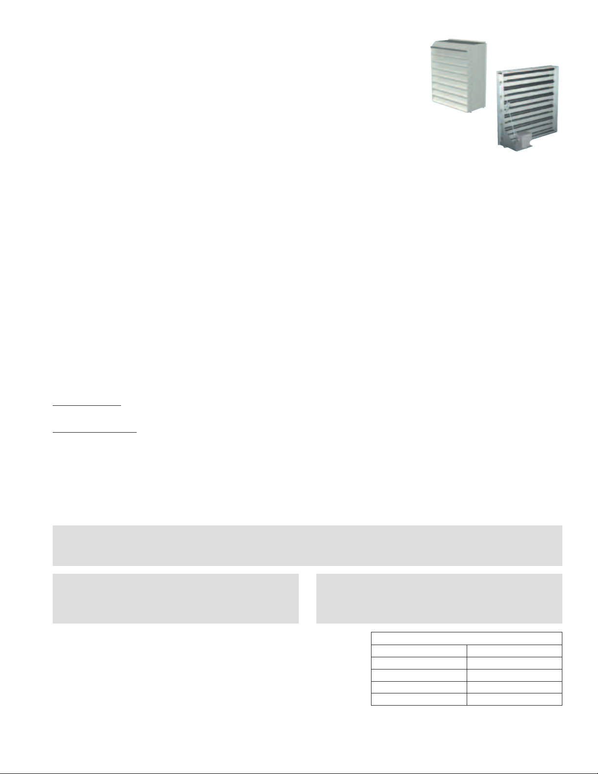
DDC Temperature Control Package
Temperature control package allows for stand-alone operation
of energy recovery units provided with supplemental cooling
and heating. Controller can be ordered for discharge or room
control. Room control would require a room thermostat (or
other call for heat or cool) be wired to the controller. A remote
panel option is also available to allow set points and other
controller parameters to be adjusted from a remote location.
For additional information, refer to the controls catalog and
Installation, Operation and Maintenance Manual.
18
Page 19

Energy Recovery Unit with Packaged DX
OPTIONAL ACCESSORIES
CO2 Sensor
This accessory is often used to provide a modulating control signal to a variable frequency drive to raise and
lower airflow in relationship to the CO2 levels in the space. This strategy is often referred to as Demand Control
Ventilation and provides further energy savings to the system. Follow instructions supplied with sensor for
installation and wiring details.
Service Outlet
120 Vac GFCI service outlet ships loose for field installation.
Requires separate power source so power is available when
unit main disconnect is turned off for servicing.
Vapor Tight Lights
Vapor tight lights provide light to each of the compartments
in the energy recovery unit. The lights are wired to a
junction box mounted on the outside of the unit. The switch
to turn the lights on is located in the unit control center.
The switch requires a separate power source to allow for
power to the lights when the unit main disconnect is off for
servicing.
19
Page 20

Energy Recovery Unit with Packaged DX
OPTIONAL ACCESSORIES
Remote Control Panel and Wiring Schematics
The remote panel is available with a number of different
alarm lights and switches to control the unit. The remote
panel ships loose and requires mounting and wiring in
the field.
The remote panel is available with the following options:
• Uniton/offswitch
• Uniton/offlight
• 7-daytimeclock
• Hand/off/autoswitch
• Dirtyfilterlight
• Economizerlight
• Frostcontrollight
• Wheelrotationsensorlight
Refer to Electrical Connections section for Field Control Wiring recommendations.
7-Day Timer or On/Off Switch
7-Day Timer
For 7-Day Timer, use blue and black wires.
Red wires should be capped off.
Hand/Off/Auto Switch
Hand/Off/Auto Switch allows the unit to
“Off” - off
“On” - Manual Operation
“Auto” - Unit is controlled by BMS, RTU, etc.
S1 - Unit On/Off
On
Off
Auto
BMS
R
C
G
R
C
G
Terminal Block
in
Unit Control
Center
Terminal Block
in
Unit Control
Center
NOTE: RTU controllers are by others.
20
Page 21

OPTIONAL ACCESSORIES
Remote Panel Wiring Schematics
Indicator Lights
powered by the ER Unit
Y1
Y2
W1
12
Energy Recovery Unit with Packaged DX
R
C
G
6
7
Unit On/Off
Frost Control
Economizer
Rotation Sensor
Dirty Filter Indicator
(Power by Others)
PS2
C
NC NO
PS3
C
NC NO
PS2
NC
C
NO
Dirty Filter
Dirty Filter
NC
PS3
Hot
L1
Refer to Pressure Switch for voltage and load ratings.
C
NO
21
Page 22

OPTIONAL ACCESSORIES
Remote Panel Wiring Schematics
Heating/Cooling Switches and Night Setback
Switch/Timer
S1
S6
S7
S4
Unit On/Off
Econ/First Stage Cooling
Second Stage Cooling
Heat
Unit On/Off
Econ/First Stage Cooling
Second Stage Cooling
Heat
Energy Recovery Unit with Packaged DX
R
C
G
Y1
Terminal Block
Y2
W1
6
7
in unit
Control Center
Terminal Block
in
Unit Control
Center
S5
Night Setback Timer
Night Setback Timer
Night Setback Switch
Night Setback Switch
12
A
22
Page 23

Energy Recovery Unit with Packaged DX
OPTIONAL ACCESSORIES
Sensors Mounted by Factory
Factory mounted temperature, pressure, and current sensors are available in the locations indicated on the unit
diagram below. A list of available sensors is shown below. The specific sensors provided on a given unit are
labeled in the unit control center on the terminal strip. Sensors are wired to the terminal strip to make it easy for
the controls contractor to connect the Building Management System for monitoring purposes.
TO
OUTSIDE
FROM
OUSTIDE
EXHAUST
BLOWER
OAF-P
OA
FILTER
EAWEF-A
OAI
EW-P
ENERGY WHEEL
OAW-P
OAAW
COOL
COIL
RAI
ACC
HEAT
COIL
RAF-P
RA
FILTER
OAF-A
SUPPLY
BLOWER
FROM INSIDE
TO INSIDE
OAD
Temperature Sensors - 1K Ohm RTD
Drawing Labels Terminal Strip Labels
OAI OA/Supply Inlet Temp
OAAW OA After Wheel
ACC After Cooling Coil Temp
OAD Supply Discharge Temp
EAW Exhaust After Wheel Temp
RAI RA/Exhaust Inlet Temp
Pressure Sensors (analog or digital)
Drawing Labels Terminal Strip Labels
OAF-P OA/Supply Filter Pressure
OAW-P Outdoor Air Wheel Pressure
RAF-P RA/Exhaust Filter Pressure
EW-P Exhaust Wheel Pressure
Amp - Current Sensors (analog or digital)
Drawing Labels Terminal Strip Labels
OAF-A Supply Fan Amps
EF-A Exhaust Fan Amps
23
Page 24

START-UP CHECKLIST FOR UNIT
Energy Recovery Unit with Packaged DX
SAFETY DANGER!
Electric shock hazard. Can cause injury or death. Before
attempting to perform any service or maintenance,
turn the electrical power to unit to OFF at disconnect
switch(es). Unit may have multiple power supplies.
SAFETY CAUTION!
Do not operate energy recovery ventilator without the
filters and birdscreens installed. They prevent the entry of
foreign objects such as leaves, birds, etc.
Use caution when removing access panels or other unit
components, especially while standing on a ladder or
other potentially unsteady base. Access panels and unit
components can be heavy and serious injury may occur.
Do not run unit during construction phase. Damage to
internal components may result and void warranty.
SAFETY CAUTION!
CAUTION!
CAUTION! WARNINGS!
• Unitwasfactorytested.Allblowers,fans,andcompressorsareset-uptoruncorrectwhensupplied
power. If any one fan is running backwards or the compressor is making loud noises, immediately turn off
the power. Switch two leads on the incoming power to the disconnect. This will ensure proper operation of
the unit. Failure to comply may damage the compressors and void the warranty.
• Donotjumperanysafetydeviceswhenoperatingtheunit.Thismaydamagecomponentswithinorcause
serious injury or death.
• Donotoperatecompressorwhentheoutdoortemperatureisbelow40ºF.
• Donotshort-cyclethecompressor.Allow5minutesbetween“on”cyclestopreventcompressordamage.
• Priortostartinguptheunit,powermustbeenergizedfor24hourswithoutacallforcooltoallowthe
compressor crankcase heaters time to boil off any liquid refrigerant present in the compressor.
• DXsystemischargedwithrefrigerant.Start-upmustbeperformedbyEPACertifiedTechnician.
Every installation requires a comprehensive start-up to ensure proper operation of the unit. As part of
that process, the following checklist must be completed and information recorded. Starting up the unit in
accordance with this checklist will not only ensure proper operation, but will also provide valuable information
to personnel performing future maintenance. Should an issue arise which requires factory assistance, this
completed document will allow unit experts to provide quicker resolve. Qualified personnel should perform
start-up to ensure safe and proper practices are followed.
Unit Model Number ___________________________ (e.g. ERCH-55)
Unit Serial Number ___________________________ (e.g. 04C99999 or 10111000)
Energy Wheel Date Code ___________________________ (e.g. 0450)
Compressor 1 Model Number ___________________________ (e.g. ZR36-XXXX)
Compressor 2 Model Number ___________________________ (e.g. ZR36-XXXX)
Start-Up Date ___________________________ (MM/DD/YYYY)
Start-Up Personnel Name ___________________________
Start-Up Company ___________________________
Phone Number ___________________________
24
Page 25

Energy Recovery Unit with Packaged DX
START-UP CHECKLIST FOR UNIT
Pre-Start Up Checklist - check boxes as items are completed
o Disconnect and lock-out all power switches
o Remove any foreign objects that are located in the energy recovery unit.
o Check all fasteners, set-screws, and locking collars on the fans, bearings, drives, motor bases and
accessories for tightness.
o Rotate the fan wheels and energy recovery wheels by hand and ensure no parts are rubbing. If rubbing
occurs, refer to Start-Up section for more information.
o Check the fan belt drives for proper alignment and tension (refer to Start-Up section for more
information).
o Filters can load up with dirt during building construction. Replace any dirty pleated filters and clean the
aluminum mesh filters in the intake hood (refer to Routine Maintenance section).
o Verify that non-motorized dampers open and close properly.
o Check the tightness of all factory wiring connections.
o Verify control wire gauge (refer to the Electrical Connections section).
o Verify diameter seal settings on the energy recovery wheel (refer to Start-Up section for more
information).
o Verify proper drain trap installation (refer to Drain Trap section).
o Check condensing fans for any damage or misalignment. Spin the blades and make sure they don’t
contact any parts and are free turning without any resistance.
o Look over the piping system. Inspect for oil at all tubing connections. Oil typically highlights a leak in
the system. If a leak is present, refer to the Maintenance section in this manual.
o Inspect all coils within the unit. Fins may get damaged in transit or during construction. Carefully
straighten fins with a fin comb.
o If there is an indirect gas-fired furnace in this unit, refer to the PVF IOM provided with this unit for __
Pre- Start-Up information.
o This unit contains a crankcase heater for each compressor which needs power supplied to it 24 hours
prior to start-up. If start-up is scheduled in 24 hours, unlock the disconnect power and energize unit.
Special Tools Required
•VoltageMeter(withwireprobes) •Thermometer
•AmperageMeter •PressureGauges
•Inclinemanometerorequivalent •TemperatureGaugescapableofmeasuringpipetemperature
•Tachometer
Start-Up Checklist
The unit will be in operational mode during start-up. Use necessary precautions to avoid injury. All data must be
collected while the unit is running. In order to measure volts & amps, the control center door must be open, and
the unit energized using a crescent wrench to turn the disconnect handle.
Start-Up Procedure
• MakesurePre-Start-Upchecklistiscomplete.
• JumperRtoG,RtoY1,andRtoY2(ifapplicable)onthecontrolboard.
• Turnthedisconnecton.After3minutescompressorswillcomeon.Makesureallfansandcompressorsare
rotating the correct direction.
WARNING!
All motor(s) / compressor(s) have been checked for rotation. If blower rotation is incorrect, wiring must be
changed at the disconnect to ensure all motor(s) / compressors are corrected.
Operation of scroll compressor(s) in this unit are directional and will be damaged if run with the wrong direction.
• Allowtheunittorununtiltherefrigerantsystemstabilizes.Approximately1-2minutes.
• Takethefollowingmeasurementswhiletheunitisrunningtoensureproperoperation.
25
Page 26

Energy Recovery Unit with Packaged DX
START-UP CHECKLIST FOR UNIT
Line Voltage - check at unit disconnect
L1-L2 ________ Volts L2-L3 ________ Volts L1-L3 _______ Volts
Motor Amp Draw:
Supply Motor Amps L1 ________ Amps L2 ________ Amps L3 ________ Amps
Exhaust Motor Amps L1 ________ Amps L2 ________ Amps L3 ________ Amps
Fan RPM: Supply Fan RPM _____________
Exhaust Fan RPM _____________
Correct fan rotation direction: Supply Fan Yes / No
Exhaust Fan Yes / No
Energy Wheel Motor: L1 ________ Amps L2 ________ Amps L3 ________ Amps
Compressor 1: L1 ________ Amps L2 ________ Amps L3 ________ Amps
Crankcase Heater ________ Amps
Compressor 2: L1 ________ Amps L2 ________ Amps L3 ________ Amps
Crankcase Heater ________ Amps
Condensing Fan 1: L1 ________ Amps L2 ________ Amps L3 ________ Amps
Condensing Fan 2: L1 ________ Amps L2 ________ Amps L3 ________ Amps
Condensing Fan 3: L1 ________ Amps L2 ________ Amps L3 ________ Amps
Outdoor Air Temperature ________ Deg F
Return Air Temperature ________ Deg F
Outdoor Air Relative Humidity ________ % RH
Return Air Relative Humidity ________ % RH
Superheat ________ Deg F Should be between 8º and 12ºF
Subcooling ________ Deg F Should be between 12º and 17ºF
Discharge Pressure PSIG Should be between 200 and 280 PSIG for R22
or 300 and 500 PSIG for R410a
Suction Line Pressure PSIG Should be between 60 and 80 PSIG for R22
or 100 and 135 PSIG for R410a
Liquid Line Temp ________ Deg F
Suction Line Temp ________ Deg F
Moisture Indicating Sight Glass Liquid Visible Yes / No Color of Center Dot Green / Yellow
Hot Gas Bypass Operational Yes / No
26
Page 27

Energy Recovery Unit with Packaged DX
OPTIONAL ACCESSORIES CHECKLIST
Refer to the respective sections in this Installation, Operation and Maintenance Manual for detailed information.
Refer to wiring diagram in unit control center to determine what electrical accessories were provided.
Provided with Unit? Frost Control Application / Operation section: Setting Factory Default
Yes No Frost Control set point 5ºF
Differential 2ºF
Timer Refer to IOM
Yes No Frost Control Modulating Refer to IOM
Economizer Application / Operation section:
Yes No Economizer (temperature)
Set point 65ºF
Offset 20ºF
Differential 2ºF
Yes No Economizer (enthalpy)
Set point B
Yes No Economizer (modulating) Refer to IOM
Optional Accessories section: Operational
Yes No Wheel Rotation Sensor Yes No N/A
Yes No OA Dirty Filter Sensor Yes No N/A
Yes No EA Dirty Filter Sensor Yes No N/A
Yes No CO
Yes No Service Outlet Yes No N/A
Yes No Vapor Tight Lights Yes No N/A
Yes No Remote Control Panel Yes No N/A
Variable Frequency Drives section: Operational
Yes No Blower VFDs Yes No N/A
Yes No Wheel VFD Yes No N/A
Damper section: Operational
Yes No Outdoor Air Damper Yes No N/A
Yes No Exhaust Air Damper Yes No N/A
Yes No Night Setback Damper Yes No N/A
Sensor Yes No N/A
2
Yes No Indirect Gas Furnace (refer to the PVF IOM, Part #461006 for start-up information)
27
Page 28

Energy Recovery Unit with Packaged DX
Belt Span
Deflection =
Belt Span
64
Belt Span
Deflection =
Belt Span
64
WRONG WRONG
MOTOR
FAN
MOTOR
UNIT START-UP
Refer to Parts List section for component locations.
Fans
The ERCH models contain a forward curved supply fan and
a forward curved exhaust fan. These forward curved fans
should be checked for free rotation. If any binding occurs,
check for concealed damage and foreign objects in the fan
housing. Be sure to check the belt drives per the start-up
recommendations in the following section.
SAFETY CAUTION!
When operating conditions of the fan are to be changed (speed, pressure, temperature, etc.), consult Greenheck to
determine if the unit can operate safely at the new conditions.
Fan Performance Modifications
Due to job specification revisions, it may be necessary to adjust or change the sheave or pulley to obtain the
desired airflow at the time of installation. Start-up technician must check blower amperage to ensure that the
amperage listed on the motor nameplate is not exceeded. Amperage to be tested with access doors closed and
ductwork installed.
Forward
Curved
Fan
Fan Belt Drives
The fan belt drive components, when supplied by Greenheck, have been carefully selected for the unit’s specific
operating condition. Caution: utilizing different components than those supplied could result in unsafe operating
conditions which may cause personal injury or failure of the following components: 1) Fan Shaft, 2) Fan Wheel,
3) Bearings, 4) Belt, 5) Motor. Tighten all fasteners and set screws securely and realign drive pulleys after
adjustment. Check pulleys and belts for proper alignment to avoid unnecessary belt wear, noise, vibration and
power loss. Motor and drive shafts must be parallel and pulleys in line (see below).
Belt Drive Installation
1. Remove the protective coating from the end of the fan shaft and assure
that it is free of nicks and burrs.
2. Check fan and motor shafts for parallel and angular alignment.
3. Slide sheaves on shafts. Do not drive sheaves on as this may result in
bearing damage.
4. Align fan and motor sheaves with a straight-edge or string and tighten.
5. Place belts over sheaves. Do not pry or force belts, as this could result
in damage to the cords in the belts.
6. With the fan off, adjust the belt tension by moving the motor base. (See
belt tensioning procedures in the Routine Maintenance section of this
manual). When in operation, the tight side of the belts should be in a
straight line from sheave to sheave with a slight bow on the slack side.
28
WRONG WRONG
Proper alignment of motor and drive shaft.
WRONG CORRECT
Page 29

UNIT START-UP
R
o
t
a
t
i
o
n
Backward Inclined
R
o
t
a
t
i
o
n
Backward Inclined
Direction of Fan Wheel Rotation
Blower access is labeled on unit. Check for proper wheel
rotation by momentarily energizing the fan. Rotation is
determined by viewing the wheel from the drive side and
should match the rotation decal affixed to the fan housing
(see Rotation Direction figures). If the wheel is rotating the
wrong way, direction can be reversed by interchanging
any two of the three electrical leads.
noise, vibration, or overheating of bearings. Refer to
the Troubleshooting section of this manual if a problem
develops.
Fan RPM
Supply fan and exhaust fan will have an adjustable motor
pulley (on 15 HP and below) preset at the factory to the
customer specified RPM. Fan speed can be increased or
decreased by adjusting the pitch diameter of the motor
pulley. Multi-groove variable pitch pulleys must be adjusted
an equal number of turns open or closed. Any increase
in fan speed represents a substantial increase in load on
the motor. Always check the motor amperage reading and
compare it to the amperage rating shown on the motor
nameplate when changing fan RPM. All access doors must
be installed except the control center door. Do not operate
units with access doors open or without proper ductwork
in place as the fan motors will overload.
Check for unusual
Energy Recovery Unit with Packaged DX
n
o
i
t
a
t
o
R
Airflow
Forward Curved
t
t
a
i
o
o
R
n
Vibration
Excessive vibration may be experienced during initial start-up. Left unchecked, excessive vibration can cause
a multitude of problems, including structural and/or component failure. The most common sources of vibration
are listed below.
1. Wheel Unbalance
2. Drive Pulley Misalignment
3. Incorrect Belt Tension
4. Bearing Misalignment
5. Mechanical Looseness
6. Faulty Belts
7. Drive Component Unbalance
8. Poor Inlet/Outlet Conditions
9. Foundation Stiffness
Many of these conditions can be discovered by careful observation. Refer
to the Troubleshooting section of this manual for corrective actions. If
observation cannot locate the source of vibration, a qualified technician using
vibration analysis equipment should be consulted. If the problem is wheel
unbalance, in-place balancing can be done.
Generally, fan vibration and noise is transmitted to other parts of the building
by the ductwork. To eliminate this undesirable effect, the use of heavy canvas
connectors is recommended.
Coils
Leak test thermal system to insure tight connections. Check for properly trapped condensate drain.
29
Page 30

Energy Recovery Unit with Packaged DX
UNIT START-UP
Inside layout of ERCH
Energy Recovery Wheel
The ERCH models contain a total energy recovery wheel. The wheels are inspected for proper mechanical
operation at the factory. However, during shipping and handling, shifting can occur that may affect wheel
operation. The wheel is accessible through the access door marked “Energy Wheel Cassette Access”. For the
ERCH-20 and ERCH-45 models, the wheel cassette slides out. Due to the size and weight of the ERCH-55 and
ERCH-90 wheels, they remain stationary and all maintenance is performed in place. There is room inside the
unit to perform energy recovery wheel servicing.
Turn the energy recovery wheels by hand to verify free operation. The wheel should rotate smoothly and should
not wobble.
Drive Belt
Inspect the drive belt. Make sure the belt rides smoothly through the pulley and over the wheel rim.
Air Seals
Check that the air seals located around the outside
of the wheel and across the center (both sides of
wheel) are secure and in good condition. Air seal
clearance is determined by placing a sheet of
paper, to act as a feeler gauge, against the wheel
face. To access seals, enter unit for ERCH-55 and
ERCH-90 or pull out the cassette for ERCH-20
and ERCH-45 following the instructions in Energy
Recovery Wheel Maintenance section. To adjust
the air seals, loosen all eight seal retaining screws.
These screws are located on the bearing support
that spans the length of the cassette through the
wheel center. Tighten the screws so the air seals
tug slightly on the sheet of paper.
Replace cassette into unit, plug in wheel drive,
replace access door and apply power. Observe by
opening door slightly (remove filters if necessary to
view wheel) that the wheel rotates freely at about
50-60 rpm.
Adjustable
Air Seals
Drive Belt
Drive Pulley
Bearing Support
Label showing
cassette serial #
and date code
30
Page 31

REFRIGERATION SYSTEM
6
7
8
HIGH PRESSURE
SWITCH
410 / MANUAL RESET
R22
600 / MANUAL RESET
R410a
CONDENSING FAN
HEAD PRESSURE
FAN CONTROL
9
275/210 PSI
R22
425/330 PSI
R410a
CONDENSER COIL
Energy Recovery Unit with Packaged DX
SIGHT GLASS
LIQUID LINE FILTER DRIER
5
CHARGING PORT
3
13
4
LOW PRESSURE SWITCH
25/80 PSI - R22
50/90 PSI - R410a
COMPRESSOR(S)
SOLENOID VALVE
SCHRAEDER VALVE
MANUAL VALVE
EQUALIZER LINE
10
CHARGING
11
PORT
13
TXV
1
EVAPORATOR COIL
2
12
HGBP
Factory Installed Refrigeration System Components
1
Thermostatic Expansion Valve (TXV) - each unit is equipped with a thermal expansion valve. The
valve controls the flow of liquid refrigerant entering the evaporator coil by maintaining a constant,
factory set superheat of 10ºF. The valve is located on the side of the evaporator coil and can be
accessed through the exhaust airstream, through the coil panel access door.
Refrigerant Distributor - attached to the TXV is a refrigerant distributor. The refrigerant distributor
2
evenly distributes the refrigerant to each circuit of the evaporator coil to provide optimum performance.
Evaporator Coil - each unit contains a single circuit evaporator coil. The coil is located in the outdoor
3
airstream, directly after the energy wheel. In the DX system, the liquid refrigerant is expanded in the
TXV, and then flows through the evaporator coil. The refrigerant enters the coil as low temp liquid/gas
where it eventually boils into a low temp, low pressure gas prior to going to the compressor. To ensure
proper operation, the coil surface must be cleaned so that air movement over the coil provides the
necessary heat transfer.
Low Limit Pressure Switch - the unit includes a low limit pressure switch (located in the compressor
4
compartment). The switch is installed in the suction line and shuts off the DX system when the suction
pressure drops to 25 psi for R22 or 50 psi for R410a. The switch has a built in auto-reset, which will
close the circuit and allow the system to run when the pressure increases back to 80 psi for R22 or
90 psi for R410a.
THERMAL EXPANSION VALVE (TXV)
HOT GAS BYPASS VALVE (HGPB)
Compressors - each unit includes 1 or 2 high efficiency scroll type compressors depending on needed
5
capacity. Scroll type compressors are essentially maintenance free since they are a self-contained, selfcooling design. The scroll compresses the refrigerant in the gaseous state to a high temperature, high
pressure gas.
Compressor protective devices:
Thermal Overload - each compressor is equipped with an auto reset thermal overload
High Temp Protection - internal devices within the compressor protect it against excessively
high discharge gas temperatures (only on compressors above 6 hp)
Crankcase Heater - Liquid refrigerant is incompressible. Therefore, a crankcase heater
is installed around each compressor in the unit to boil any liquid refrigerant that may
be absorbed into the oil during idle periods. System power energizes the heater; it is
recommended the heater is allowed to run 24 hours prior to compressors being started.
31
Page 32

REFRIGERATION SYSTEM
Factory Installed Refrigeration System Components
Condensing Coil - each unit contains a condensing coil mounted on the exterior of the unit. High
6
temperature, high pressure gas from the compressor enters the coil and is eventually cooled into a high
temperature, high pressure liquid. The condensing fans move air over the coil which pulls the heat out of
the refrigerant. To ensure proper operation, the coil must be cleaned so that air movement over the coil
provides the necessary heat transfer.
Condenser Fans - depending on capacity, the unit is equipped with either 2 or 3 direct-drive
7
condensing fans. The fans provide the necessary airflow to cool the refrigerant in the condensing coil.
Depending on head pressure, one fan may not be running, which is normal operation for this unit and
does not highlight a problem. The motors are equipped with sling protection to guard against water
penetration, and are thermally protected. The thermal overloads shut down the condensing fans.
High Limit Pressure Switch - to safely shutdown the DX system, in case of an increase in refrigerant
8
pressure, a high limit pressure switch is included (located in compressor compartment). The switch is
located in the compressor compartment. It trips when refrigerant pressure increase to 410 psi for the
R22 (600 psi for R410a) in the liquid line, and can only be manually reset when the pressure drops below
290 psi. Typically if the high limit switch trips, a failure in the system has occurred and more investigation
is needed to determine the underlying problem.
Head Pressure Cycle Switch - to maintain proper refrigerant pressures, a Fan-Cycle switch that
9
operates on head pressure is installed in the liquid line. When liquid line refrigerant pressure increases to
275 psi for R22 (425 psi for R410a), the switch closes and turns on an additional condensing fan to aid in
cooling the refrigerant. After turning on, the fan will run until liquid line pressure drops down to 210 psi
for R22 (330 psi for R410a) where it cycles off. The switch is located in the compressor compartment.
Energy Recovery Unit with Packaged DX
Liquid Line Filter Drier - the liquid line filter drier prevents moisture and foreign matter from entering
10
the thermal expansion valve. It is mounted in the compressor compartment.
Moisture Indicating Sight Glass - moisture in a DX system can cause great harm and break down the
11
refrigerant. Located in the compressor compartment is a moisture indicating sight glass. During normal
operating conditions, the sight glass should typically be liquid. Some gas is acceptable, but excessive
bubbles may indicate improper charge or a leak in the system. A green dot means moisture is below a
safe operation level in the refrigerant, while a yellow dot indicates moisture has been introduced into the
system and needs to be addressed.
Hot Gas Bypass Valve - on units equipped with hot bypass, hot gas from the compressor is injected
12
into the liquid line of the evaporator coil after the TXV. This process starts to occur when suction gas
temperatures drop below 28ºF, which is 32º–34ºF coil surface temperature. Hot gas helps prevent the
evaporator coil from freezing up and the compressor from cycling. The valve is factory set, but can be
adjusted to exact specifications once installed in the field.
Valve Adjustment - to adjust the valve, connect a pressure gauge to the suction line and
block the entering air to the evaporator coil. The Valve should begin to open when the suction
pressure drops to approximately 58 PSIG for R22 and 115 PSIG for R410a (the valve will feel
warm to the touch). Adjustments are made by first removing the cap on the valve and then
turning the adjusting stem clockwise to increase the setting pressure and counterclockwise
to decrease the setting pressure. Allow several minutes between adjustments for system to
stabilize. When adjustment is complete, replace the cap on the valve.
Access Ports - For easy measurement and charging access, several ports are provided throughout the
13
system. These can be used to measure system pressures, and also charge or evacuate the system. Most
ports are located in the compressor compartment for easy access.
32
Page 33

ROUTINE MAINTENANCE
Energy Recovery Unit with Packaged DX
SAFETY DANGER!
Electric shock hazard. Can cause injury or death. Before
attempting to perform any service or maintenance,
turn the electrical power to unit to OFF at disconnect
switch(es). Unit may have multiple power supplies.
This unit requires minimal maintenance to operate properly. To ensure proper operation and longevity, the
following items should be completed. The items in this list assume a relatively clean air environment, and may
require attention more frequently in a dirty or dusty area. If this unit contains an Indirect Gas Heater, refer to the
Installation, Operation and Maintenance Manual provided with the unit for maintenance purposes. A Certified
Technician should complete all refrigerant systems checks.
Use caution when removing access panels or other unit
components, especially while standing on a ladder or
other potentially unsteady base. Access panels and unit
components can be heavy and serious injury may occur.
SAFETY CAUTION!
Monthly
External Filter Check for cleanliness – clean if required
Internal Filter Check for cleanliness – replace if required
Condensate Drain Inspect and clean – refill with water
Semi-Annually
Fan Belts Check for wear, tension, alignment
Energy Recovery Wheel Check for cleanliness – clean if required
Check for belt wear
Check pulley, bearings, and motor
Annually
It is recommended that the annual inspection and maintenance occur at the start of the cooling season. After
completing the checklist, follow the unit start-up checklist provided in the manual to ensure the refrigeration
system operates in the intended matter.
Lubrication Apply lubrication where required
Dampers Check for unobstructed operation
Motors Check for cleanliness
Fan Belts Check for wear, tension, alignment
Motors Check for cleanliness
Blower Wheel & Fasteners Check for cleanliness
Check all fasteners for tightness
Check for fatigue, corrosion, wear
Bearings Check for cleanliness
Check set screws for tightness
Energy Recovery Wheel Check for cleanliness – clean if required
Check belt for wear
Check pulley, bearings, and motor
Door Seal Check if intact and pliable
Evaporator Coil Maintenance Check for cleanliness – clean if required
Condenser Coil Maintenance Check for cleanliness – clean if required
Condensate Drain Inspect and clean – refill with water
Condensing Fan Blades and Motor Check for cleanliness
Check all fasteners for tightness
Check for fatigue, corrosion, and wear
Wiring Connections Check all connections for tightness
33
Page 34

Energy Recovery Unit with Packaged DX
ROUTINE MAINTENANCE
Lubrication
Check all moving components for proper lubrication. Apply lubrication where required. Any components
showing excessive wear should be replaced to maintain the integrity of the unit and ensure proper operation.
Dampers
Check all dampers to ensure they open and close properly and without binding. Backdraft dampers can be
checked by hand to determine if blades open and close freely. Apply power to motorized dampers to ensure the
actuator opens and closes the damper as designed.
Fan Belts
Belts must be checked on a regular basis for wear, tension, alignment, and dirt accumulation. Premature
or frequent belt failures can be caused by improper belt tension (either too loose or too tight) or misaligned
sheaves. Abnormally high belt tension or drive misalignment will cause excessive bearing loads and may result
in failure of the fan and/or motor bearings. Conversely, loose belts will cause squealing on start-up, excessive
belt flutter, slippage, and overheated sheaves. Both loose and tight belts can cause fan vibration.
When replacing belts on multiple groove drives, all belts should be changed to provide uniform drive loading.
Do not pry belts on or off the sheave. Loosen belt tension until belts can be removed by simply lifting the
belts off the sheaves. After replacing belts, insure that slack in each belt is on the same side of the drive. Belt
dressing should never be used.
Do not install new belts on worn sheaves. If the sheaves have grooves worn in them, they must be replaced
before new belts are installed.
Deflection =
Belt Span
Proper fan belt settings
Belt Span
64
The proper belt setting is the lowest tension
at which the belts will not slip under peak load
operation. For initial tensioning, set the belt
deflection at 1/64-inch for each inch of belt span
(measured half-way between sheave centers).
For example, if the belt span is 64 inches, the
belt deflection should be 1 inch (using moderate
thumb pressure at mid-point of the drive). Check
belt tension two times during the first 24 hours of
operation and periodically thereafter.
Fan Motors
Motor maintenance is generally limited to cleaning and lubrication. Cleaning
should be limited to exterior surfaces only. Removing dust and grease buildup
on the motor housing assists proper motor cooling. Never wash-down motor
with high pressure spray. Greasing of motors is only intended when fittings are
provided. Many fractional motors are permanently lubricated for life and require
no further lubrication.
Fan Wheel & Fasteners
Wheels require very little attention when moving clean air. Occasionally oil and
dust may accumulate on the wheel causing imbalance. When this occurs the
wheel and housing should be cleaned to assure smooth and safe operation.
Inspect fan impeller and housing for fatigue, corrosion or wear.
Routinely check all fasteners, set screws and locking collars on the fan, bearings, drive, motor base and
accessories for tightness. A proper maintenance program will help preserve the performance and reliability
designed into the fan.
34
Page 35

ROUTINE MAINTENANCE
Energy Recovery Unit with Packaged DX
Internal Filter Maintenance
The ERCH units will typically be provided with
2-inch, pleated filters in the outdoor air and
exhaust airstream. These filters should be
checked per a routine maintenance schedule
and replaced as necessary to ensure proper
airflow through the unit. See table at right
for pleated filter size and quantity for each
Model
ERCH-20 20 in. x 20 in. 2 2
ERCH-45 20 in. x 25 in. 3 3
ERCH-55 16 in. x 20 in. 6 6
ERCH-90 20 in. x 20 in. 8 8
Filter Size and Quantities
Internal
Filter Size
Quantity
Supply
Quantity
Exhaust
unit. Replacement filters shall be of same
performance and quality as factory installed filters. Filter type must be pleated design with integral metal grid.
Two acceptable filter replacements are Aerostat Series 400 or Farr 30/30®.
Outdoor Air Filters: Access to the outdoor air filters is through the door labeled as “Filter Access” on the
outdoor air side of the unit.
Exhaust Air Filters: Access to the exhaust air filters is through the door labeled as “Filter Access” on the
exhaust air side of the unit.
Refer to Access Door Descriptions section for additional information on filter locations.
External Filter Maintenance
Aluminum mesh, 2-inch deep filters are located in the supply weatherhood (if the
weatherhood option was purchased). Filters should be checked and cleaned on
a regular basis for best efficiency. The frequency of cleaning depends upon the
cleanliness of the incoming air. These filters should be cleaned prior to start-up.
To access these filters, remove bottom bolt in the access door on the side of
the weatherhood. Slide the access door up and then pull bottom out to remove
door. Then, slide the filters out (see figure at right).
Clean filters by rinsing with a mild detergent in warm water.
Outdoor air intake hood
mesh filter access
35
Page 36

Energy Recovery Unit with Packaged DX
ROUTINE MAINTENANCE
Coil Maintenance
**WARNING**
REFER TO SAFETY WARNING ON COVER
DO NOT OPERATE ENERGY RECOVERY VENTILATOR WITHOUT THE FILTERS AND BIRDSCREENS INSTALLED.
THEY PREVENT THE ENTRY OF FOREIGN OBJECTS SUCH AS LEAVES, BIRDS, ETC.
DO NOT REMOVE ACCESS PANELS OR OTHER UNIT COMPONENTS WHILE STANDING ON A LADDER OR OTHER
UNSTEADY BASE. ACCESS PANELS AND UNIT COMPONENTS ARE HEAVY AND SERIOUS INJURY MAY OCCUR.
Filters
Filters upstream of the coil should be checked regularly. If the filters are dirty, they should be cleaned or
replaced. It is important that the coils stay clean to maintain desired airflow. See Filter Maintenance section for
additional information.
Coil Maintenance
1. Coils must be cleaned to obtain maximum performance. Check once a year under normal operating
conditions and if dirty, brush or vacuum clean. Soiled fins reduce the capacity of the coil, demand more
energy from the fan, and create an environment for odor and bacteria to grow and spread through the
conditioned zone. High pressure water (700 psi or less) may be used to clean coils with fin thickness over
0.0095 inches thick. TEST THE SPRAY PRESSURE over a small corner of the coil to determine if the fins will
withstand the spray pressure.
For coils with fragile fins or high fin density, foaming chemical sprays and washes are available. Many coil
cleaners contain harsh chemicals, so they must be used with caution by qualified personnel only. Care must
be taken not to damage the coils, including the fins, while cleaning.
CAUTION: Fin edges are sharp.
**WARNING**
BIOLOGICAL HAZARD. MAY CAUSE DISEASE. CLEANING SHOULD BE PERFORMED BY QUALIFIED PERSONNEL.
2. Drain pans in any air conditioning unit will have some moisture in them, therefore, algae and other organisms
will grow due to airborne spores and bacteria. Periodic cleaning is necessary to prevent this buildup from
plugging the drain and causing the drain pan to overflow. Inspect twice a year to avoid the possibility
of overflow. Also, drain pans should be kept clean to prevent the spread of disease. Cleaning should be
performed by qualified personnel.
36
Page 37

ROUTINE MAINTENANCE
Energy Recovery Wheel Maintenance
Annual inspection of the energy recovery wheel is recommended. Units
ventilating smoking lounges and other non-clean air spaces should
have energy recovery wheel inspections more often based upon need.
Inspections for smoke ventilation applications are recommended
bimonthly to quarterly until a regular schedule can be established.
ACCESSING ENERGY RECOVERY WHEEL
The ERCH units have one energy recovery wheel. Open the outdoor
air filter door to access the wheel. For the ERCH-20 and ERCH-45
models, the wheel cassette slides out. Due to the size and weight of
the ERCH-55 and ERCH-90 wheels, they remain stationary and all
maintenance is performed in place. There is room inside the unit to
perform energy recovery wheel servicing. Filters must be removed to
access stationary wheels.
Energy Recovery Unit with Packaged DX
**WARNING: Disconnect power to the unit before performing
any type of service.
REMOVING THE ENERGY RECOVERY WHEEL SEGMENTS
Models ERCH-20, 45, 55 & 90
Steel retainers are located on the
inside of the wheel rim (see diagram at
right). Push the retainer toward center
of wheel, then lift up and away to
release segments (see below).
Catch Segment
Retainer
Lift away from
segment
Push toward center
Access to wheel through
outdoor air filter door
Bracket Segment
Retainer
Inside of wheel rim
Spoke
Center of Wheel
Wheel segment removed
IMPORTANT! PLACE RETAINERS BACK IN THE ORIGINAL
POSITION BEFORE ROTATING THE ENERGY
RECOVERY WHEEL. OTHERWISE DAMAGE TO
RETAINER WILL OCCUR.
37
Page 38

Energy Recovery Unit with Packaged DX
ROUTINE MAINTENANCE
CLEANING THE ENERGY RECOVERY WHEEL
If the wheel appears excessively dirty, it should be cleaned to ensure maximum operating efficiency. Only
excessive buildup of foreign material needs to be removed. DISCOLORATION AND STAINING OF ENERGY
RECOVERY WHEEL DOES NOT AFFECT ITS PERFORMANCE.
Thoroughly spray wheel matrix with household cleaner such as Fantastic® or equivalent. Gently rinse with warm
water and using a soft brush remove any heavier accumulation. A detergent/water solution can also be used.
Avoid aggressive organic solvents, such as acetone. The energy recovery wheel segments can be soaked in the
above solution overnight for stubborn dirt or accumulation.
After cleaning is complete, shake the excess water from the wheel or segments. Dry wheel or segments
before placing them back into the cassette. Place wheel or segments back into cassette by reversing removal
procedures.
** DO NOT CLEAN ENERGY RECOVERY WHEEL SEGMENTS WITH WATER IN EXCESS OF 140ºF.
** DO NOT DRY ENERGY RECOVERY WHEEL SEGMENTS IN AIR IN EXCESS OF 140ºF.
** THE USE OF A PRESSURE WASHER TO CLEAN SEGMENTS IS NOT RECOMMENDED. DAMAGE COULD
RESULT.
Energy Recovery Wheel Belt
Inspect belts each time filters are replaced. Belts that
look chewed up or are leaving belt dust near the motor
pulley may indicate a problem with the wheel. Be sure to
inspect wheel for smooth and unrestricted rotation. If a
belt requires replacement, contact the local Greenheck
representative. Instructions for replacement will ship with
the new belt.
Energy Recovery Wheel Bearings
In the unlikely event that a wheel bearing fails, access is
available through the outdoor air filter door and through
a removable plate in the divider in the unit (accessed
through the exhaust air filter door). Contact the local
Greenheck representative for detailed instructions on how
to replace the bearing.
Wheel Belt & Pulley
38
Wheel Bearing
Page 39

PARTS LIST
Energy Recovery Unit with Packaged DX
10
5
4
3
9
6
7
8
11
12
13
2
Model ERCH
(shown with standard integral condensing section and optional electric heater)
1. Supply blower
- Forward curved fan
- Adjustable motor mount for belt tensioning
- Adjustable sheaves for speed control
2. Vibrations isolators (quantity 4 per blower)
- Neoprene
3. Energy recovery wheel cassette
4. Removable energy recovery wheel segments
5. Optional supply weatherhood with 2 in. aluminum
mesh filter
6. Optional exhaust weatherhood with bird screen
7. Optional supply and exhaust air filter racks for
2 in. pleated, 30% efficient filters
1
8. Electrical control box (standard features)
- Single point power
- Disconnect interlocked with access door
- Motor starters for the supply blower, exhaust
blower and energy wheel motors.
- 24 Vac, control circuit with terminal strip
9. Coil section houses supply air tempering options
- Packaged DX for cooling
- Electric or hot water heat
- Indirect gas heat
10. Exhaust blower
11. Compressor(s)
12. Condensing fans
13. Condensing coil
39
Page 40

Energy Recovery Unit with Packaged DX
SEQUENCE OF OPERATION
Basic Unit
The ERCH units are pre-wired such that when a call for outside air is made (via field supplied 24 Vac control
signal wired to unit control center), the supply fan, exhaust fan and energy wheel are energized and optional
motorized dampers open. The ERCH units can be supplied with or without heating coils. Controls can be
supplied by Greenheck or by the controls contractor. If supplied by the controls contractor, they would
provide, mount, and wire any temperature controllers and temperature or relative humidity sensors required
for the unit to discharge air at the desired conditions. However, temperature, pressure, and current sensors
can be provided by Greenheck for purposes of monitoring via the Building Management System (see Optional
Accessories section).
Summer Operation:
Outdoor air is preconditioned (temperature and moisture levels are decreased) by the transfer of energy from
the cooler, drier exhaust air via the energy recovery wheel. Units supplied with cooling coils can further cool the
air coming off the wheel and strip out moisture to levels at or below room design. A heating coil downstream of
the cooling coil can reheat the air to a more comfortable discharge temperature to the space.
Standard DX Sequence of Operation:
Unit without economizer
Ambient temperatures above 55ºF
• Firstcallforcool,theunitwillturnonthefirstcompressor.
• Onthesecondcallforcool,theunitwillturnonthesecondcompressorifavailable.
(10 or larger tonnage system).
Unit without economizer
Ambient temperatures below 55ºF
• DXsystemlockedoutandwillnotoperate.
Unit with economizer
With economizer conditions available and ambient temperature above 55ºF
• Firstcallforcool-theunitwillcheckifitcanuseeconomizerair.Ifitcan,thewheelwillshutoffor
modulate and the cooling coil will be de-energized.
• Secondcallforcool-theunitwillturnonacompressortoprovidethespacewithfurthercooling.
With economizer conditions available and ambient temperature below 55ºF
• Firstcallforcool-theunitwillengageeconomizerallowingfreecoolingdowntominimumsetpoint,
factory set at 50ºF.
• Secondcallforcool-theDXsystemislockedout,notallowingcompressorstorunbelow55ºF.First
stage of cooling will still operate unless ambient temperature drops below economizer set point.
Without economizer conditions available and ambient temperature above 55ºF
• Firstcallforcool-theunitwillturnoncompressorone.
• Secondcallforcool-theunitwillturnonthesecondcompressorifavailable.
(10 or larger tonnage system).
Economizer Operation: See Economizer Application/Operation section.
Winter Operation:
Outdoor air is preconditioned (temperature and moisture levels are increased) by the transfer of energy from
the warmer, more humid exhaust air via the energy recovery wheel. Units supplied with heating coils can further
heat the air coming off the wheel to levels at or above room design.
Frost Control Operation: See Frost Control Application/Operation section.
40
Page 41

Energy Recovery Unit with Packaged DX
SEQUENCE OF OPERATION
Other Accessories:
Rotation Sensor See Optional Accessories section
Dirty Filter Sensor See Optional Accessories section
CO2 Sensor See Optional Accessories section
Night Setback On a call for night setback (unoccupied mode), the outdoor air damper will
close and the energy wheel and exhaust fan will be de-energized. The night
setback dampers will open and the supply fan will remain on, providing 100%
recirculation. Units supplied with heating and cooling coils will temper air as
required by the controls to maintain desired conditions in the space.
DX Safety and General Control Sequence
To prevent damage to the system, there is a safety loop incorporated into the
controls. This loop includes a check to make sure the supply fan starter is pulled
in, ambient temperature is above 55ºF, and the low- and high-pressure switches
are not tripped out. After this loop is verified, a relay then pulls in to start the
anti-cycle timer. (Typical setting is 3 minutes). Once the timer has counted down,
only then can the compressor contact pull in. Once the compressor contact pulls
in, the first stage of condensing fans turns on. If pressure in the condensing coil
increases to a point at which more heat needs to be removed from the system,
the fan cycle switch will close and the second stage of condensing fans turns on.
41
Page 42

Energy Recovery Unit with Packaged DX
Troubleshooting – Airflow
Test and Balance Report
The Test and Balance Report (TAB) is utilized to determine whether the appropriate amount of outdoor air
and exhaust air is being supplied and removed from a building, respectively. There are no set rules on what
information must be included in a TAB report. As such, if a TAB report indicates that the airflow on a unit is low,
prior to contacting the factory, please determine the following information:
Unit #1 Unit #2 Unit #3 Unit #4
Model Number
Serial Number
Name Plate Information
Voltage
Hertz
Phase
Outdoor Air Fan Amps
Exhaust Fan Amps
Outdoor Air Fan Horsepower
Exhaust Fan Horsepower
Design Airflow
Outdoor Air
Exhaust
Measured Airflow
Outdoor Air
Exhaust
Measured Data
Blower Rotation
Outdoor Air Fan RPM
Exhaust Fan RPM
Outdoor Air Fan Amp Draw
Exhaust Fan Amp Draw
Pressure Drop Across Energy Recovery Wheel
Outdoor Air Side
Exhaust Side
Airflow problems can often be tied back to improper ductwork installation. Be sure to install ductwork in
accordance with SMACNA and AMCA guidelines.
42
Page 43

Energy Recovery Unit with Packaged DX
Troubleshooting – General Unit
Symptom Possible Cause Corrective Action
Blown fuse or open circuit breaker.
Defective motor or capacitor. Replace.
Replace fuse or reset circuit breaker and check
amps.
Blower fails to
operate
Motor starters
“chatter” or
do not pull in
Motor over amps
Motor starter overloaded. Reset starter and check amps.
Electrical.
Drive.
Control power (24 Vac) wiring run is too long
(resistance should not exceed 0.75 ohms).
Incoming supply power is less than anticipated.
Voltage supplied to starter coil must be within
+10% / -15% of nominal voltage stated on the coil.
CFM too high. Check cfm and adjust drives if needed.
Static pressures are higher or lower than
design.
Blower rotation is incorrect. Check rotation and reverse if necessary.
Motor voltage incorrect.
Motor horsepower too low.
Shorted windings in motor. Replace motor.
Check for On/Off switches. Check for correct
supply voltage.
Check for broken or loose belts. Tighten loose
pulleys.
Shorten wiring run to mechanical room or install
a relay which will turn unit on/off (C/F for relay
information). Increase wire gauge size so that
resistance is .075 ohms or less.
Need to increase supply power or use a special
control transformer which is sized for the actual
supply power.
If higher, ductwork should be improved.
If lower, fan rpm should be lower.
Check motor nameplate versus supplied
voltage.
See specifications and catalog for fan curves to
determine if horsepower is sufficient.
Low airflow (cfm)
High airflow (cfm)
Unit damper not fully open. Adjust damper linkage or replace damper motor.
System static pressure too high.
Blower speed too low.
Fan wheels are operating backwards.
Dirty filter or energy wheel.
Leaks in ductwork. Repair.
Elbows or other obstructions may be
obstructing fan outlet.
Belt slippage. Adjust belt tension.
Blower fan speed too high.
Filter(s) not in place. Install filters.
Insufficient static pressure (Ps) (airflow
resistance).
Improve ductwork to eliminate losses using
good duct practices.
Check for correct drives and rpm with catalog
data.
For 3-phase, see Direction of Fan Wheel
Rotation under Unit Start-Up section.
Follow cleaning procedures in Routine
Maintenance section.
Correct or improve ductwork.
Check for correct fan rpm. Decrease fan speed
if necessary.
Induce Ps into system ductwork. Make sure
grilles and access doors are installed. Decrease
fan speed if necessary.
Always have a completed Pre-Start-Up Checklist, unit Start-Up Checklist, and Optional Accessories Checklist prior to requesting parts or
service information.
43
Page 44

Energy Recovery Unit with Packaged DX
Troubleshooting – General Unit
Symptom Possible Cause Corrective Action
One or both
blowers turn off
intermittently and
back on after
about 2 minutes
Exhaust Only frost control sensors are tripping.
Adjust frost temperature sensor set point as
needed.
Energy wheel does
NOT turn
Energy wheel runs
intermittently
Air seals are too tight.
“Economizer” sensors are operating.
No power to wheel motor.
Wheel drive belt.
VFD overload. (OL1 on readout)
Wheel motor overloads are tripping, due to
rubbing between wheel and air seals.
Fan wheel rubbing on inlet.
Bearings.
Wheel out of balance. Replace or rebalance.
Loose wheel on shaft. Tighten wheel setscrew.
Loose motor or blower sheave. Tighten sheave setscrew.
See Energy Recovery Wheel under Unit Start-Up
section.
Adjust temperature or enthalpy set points as
needed.
Make sure wheel drive is plugged in. Verify
power is available.
Check for loose or broken belts. Replace belts
(consult factory).
Refer to VFD section. Compare motor amp
rating to setting in VFD. Adjust accordingly.
Recheck air seals, make sure they are not too
tight. See Energy Recovery Wheel under Unit
Start-Up Section.
Adjust wheel and/or inlet cone. Tighten wheel
hub or bearing collars on shaft.
Replace defective bearings (s). Lubricate
bearings. Tighten collars and fasteners.
Belts too loose. Adjust belt tension after 24 hours of operation.
Excessive noise
or vibration
Always have a completed Pre-Start-Up Checklist, unit Start-Up Checklist, and Optional Accessories Checklist prior to requesting parts or
service information.
Belts too tight.
Worn belt. Replace.
Motor base or blower loose. Tighten mounting bolts.
Buildup of material on wheel. Clean wheel and housing.
Bearing and drive misaligned. Realign.
Noise being transmitted by duct.
Loosen to maintain a 3/8 inch deflection per
foot of span between sheaves.
Make sure ductwork is supported properly.
Make sure ductwork metal thickness is sized for
proper stiffness. Check duct size at discharge
to ensure that air velocities are not too high.
44
Page 45

Energy Recovery Unit with Packaged DX
Troubleshooting – General Refrigeration Circuit
IMPORTANT TROUBLESHOOTING
NOTE!
Before any components are changed on the
refrigeration system, the cause of the failure must be
identified. Further problems will exist unless the true
cause or problem is identified and corrected.
NOTE: Unit is equipped with a phase loss/phase reversal control. If system does not start, check phase of electrical supply.
Do not release refrigerant to the atmosphere! If
required service procedures include the adding or
removing of refrigerant, the service technician must
comply with all federal, state and local laws. The
procedures discussed in this manual should only be
performed by a qualified HVAC Technician.
IMPORTANT!
Symptom Possible Cause Corrective Action
Open disconnect switch or circuit breaker. Close switch and / or breaker.
Check voltage to contactor coil, transformer,
slave relay, system. Replace parts as necessary.
Check for reason and repair. Replace fuse after
correcting problem.
Check line voltage. If more than 10% from
compressor marking, correcting is necessary.
Motor thermal protector automatically resets.
Allow time (2 hrs.) for compressor to cool down
so protector will reset. Restart and check for
reason overheat occurred.
Check motor for open circuit, short circuit,
grounded windings or burn out.
Compressor may be seized; check refrigerant.
If necessary, replace compressor.
Compressor
will not run
or
does not
try to start
Compressor contactor not closing.
Blown fuse or tripped breaker.
Low line voltage.
Compressor motor protector open.
Compressor defective.
If manual reset (high pressure), reset switch.
(Switch opens at 400 psi and will not reset
High or low pressure switch open or defective.
Open room thermostat or control
(no cooling required).
Loose wiring.
Low refrigerant charge. Check refrigerant pressures.
Compressor starts
but cuts out on low
pressure
Low pressure
switch activates
at 25 psig for R22,
50 psig for R410a
Always have a completed Pre-Start-Up Checklist, unit Start-Up Checklist, and Optional Accessories Checklist prior to requesting parts or
service information.
Airflow restricted.
Restriction in refrigerant line.
Defective low pressure switch. Replace.
above 250 psi for R22 or 600/420 respectively
for R410a).
If auto reset (low pressure) does not reset and
everything else is OK, replace switch.
Check room temperature. If temperature is
proper, wait for thermostat to close.
Check all wire terminals and tighten as
necessary.
Check for dirty evaporator coil, dirty filters,
dampers closed, iced evaporator coil, improper
belt, check motor amps, check duct design.
Check refrigerant pressure, check and adjust
thermal expansion valve. If not functioning
properly, check for pressure drop across the
filter drier.
45
Page 46

Energy Recovery Unit with Packaged DX
Troubleshooting - General Refrigeration Circuit
Symptom Possible Cause Corrective Action
Refrigerant overcharge. Check pressures, charge by subcooling.
Compressor starts
but cuts out on high
pressure switch
High pressure
activates at
410 psig for R22,
600 psig for R410a
Compressor cuts out
on thermal overload
Condenser fan motor defective. Check fan motor.
Condenser coil inlet obstructed or dirty. Check coil and inlet clearances.
Air or non-condensables in system.
Defective high pressure switch. Replace.
Restriction in discharge or liquid line.
Condensing fan relay not pulling in. Replace.
Low voltage. Check voltage.
Sustained high discharge pressure.
High suction and discharge pressures.
Defective compressor overload.
Improper refrigerant charge. Check subcooling.
Check high side equalized pressure reading
with equivalent outdoor temperature.
Check refrigerant line pressures, check thermal
expansion valves.
Check running amperage and conditions
described under ‘Low suction pressure’
symptoms.
Check thermal expansion valve setting, check
for air in system.
If compressor is hot, allow compressor to cool
for two hours. Recheck for open circuit.
Compressor hums,
but will not start
Improperly wired. Review wiring schematics.
Loose wiring. Check all connections and wires.
Defective start relay. Replace relay.
Motor windings damaged. Verify amp draw.
Improperly wired. Review wiring schematics.
Low line voltage. Check voltage.
Loose wiring. Check all connections.
Defective start or run capacitor.
Defective relay start. Replace relay.
Motor winding damaged. Verify amp draws.
Internal compressor mechanical damage. Replace.
Check run capacitor for compressor and fan
motor.
Always have a completed Pre-Start-Up Checklist, unit Start-Up Checklist, and Optional Accessories Checklist prior to requesting parts or
service information.
46
Page 47

Energy Recovery Unit with Packaged DX
Troubleshooting - General Refrigeration Circuit
Symptom Possible Cause Corrective Action
Refrigerant overcharge. Check pressures and subcooling.
Compressor noisy
or vibrating
High suction
pressure
Liquid floodback.
Tubing rattle.
Scroll compressor rotating in reverse (3 phase). Rewire for opposite rotation.
Worn or damaged compressor. Replace the compressor.
Improper mounting on unit base. Check that compressor is properly isolated.
Excessive load on evaporator coil.
Compressor is unloaded.
Expansion valve not secured to suction line.
Check thermal expansion valve setting. Check
for refrigerant overcharge.
Dampen tubing vibration by taping or clamping.
Carefully bend tubing away from contact where
possible.
Check for high entering wet bulb temperature.
Check for excessive air.
Check head pressure, check thermal expansion
valve if not functioning properly, check pressure
drop across filter drier.
Check the thermal expansion valve, ensure bulb
is insulated.
Check superheat. If superheat is high, then
valve is out of control and pegged wide open.
•Checkbulbforcontact.
•Adjustvalveforsuperheat.
•Replacevalvepowerheadorvalve.
High discharge
pressure
Thermostatic expansion valve pressure limit
feature incorrect or inoperative. Overfeeding.
Room load too large. Reduce the load or add more equipment.
Overcharged. Check pressures and subcooling.
Thermal expansion valve setting.
Air inlet to condenser dirty or obstructed.
Condenser fan motor defective. Check condenser fan motor and capacitor.
Too much refrigerant. Remove excess refrigerant.
Non-condensable in system. Remove non-condensable from system.
Dirty condenser coil. Clean condenser coil.
Condenser fan not running or running
backwards.
Discharge service valve partially closed. Open valve.
High load conditions. Add more equipment or reduce load.
Check bulb location and clamping. Adjust
superheat. Replace expansion valve power
head.
Check thermal expansion setting and calibrate
superheat.
Check for proper clearances and possible air
recirculating.
Check electrical circuit and fuse. Check fan
cycling controls.
Always have a completed Pre-Start-Up Checklist, unit Start-Up Checklist, and Optional Accessories Checklist prior to requesting parts or
service information.
47
Page 48

Energy Recovery Unit with Packaged DX
Troubleshooting - General Refrigeration Circuit
Symptom Possible Cause Corrective Action
Refrigerant undercharge. Check pressures and subcooling.
Low suction
pressure
Low discharge
pressure
Blower running backward.
Loose blower, pulley or belts. Check drive pulley alignment, belt tension.
Low entering air temperature (low load
condition).
Refrigerant leak.
Evaporator dirty or iced up or airflow restricted.
Plugged liquid line filter-drier. Replace filter-drier.
Improper suction pressure regulator setting. Check setting and correct as required.
Expansion valve defective, superheat too high,
or valve too small.
Moisture in system. Reclaim refrigerant, check for leaks, recharge.
Insufficient refrigerant charge.
Defective or improperly adjusted expansion
valve.
Low suction pressure. See “Low suction pressure”.
Interchange any two wires from 3 phase
disconnect.
Check entering air wet bulb conditions.
Check system for leaks. Repair leaks and add
refrigerant.
Check defrost system. Clean the coil.
Check fan operation. Check airflow.
Adjust valve for proper superheat or replace the
expansion valve if too small or defective.
Check subcooling, check for leak. Repair leak
and add refrigerant.
Check superheating and adjust thermal
expansion valve.
Faulty condenser temperature controls.
Thermostat location or malfunction.
Improper refrigerant charge. Check subcooling, verify superheat.
Defective high or low pressure control. Check high or low pressure switch.
Liquid floodback. Possible tight bearings, see above.
Compressor
short cycles
Always have a completed Pre-Start-Up Checklist, unit Start-Up Checklist, and Optional Accessories Checklist prior to requesting parts or
service information.
Defective expansion valve. Check thermal expansion valve and superheat.
Poor air distribution. Check ductwork for recirculating.
High discharge pressure. See “High discharge pressure”.
Leaking discharge valves in compressor. See “High suction pressure”.
Low airflow at evaporator(s).
Incorrect unit selection (oversized). Contact factory.
Check condenser controls and reset to obtain
desired condensing temperature.
Check thermostat, check heat anticipator
setting.
Check blower operation and airstream
restrictions.
48
Page 49

Energy Recovery Unit with Packaged DX
Troubleshooting - General Refrigeration Circuit
Symptom Possible Cause Corrective Action
Low or no
oil pressure
Compressor
loses oil
Low oil level (trapped oil in evaporator or
suction line).
Excessive liquid refrigerant in the crankcase.
Worn oil pump. Replace the oil pump.
Worn compressor bearings. Replace the compressor.
Loose fitting on oil line or pump housing gasket
leaking. (R22 only)
Compressor short cycling. Check low pressure control setting.
Refrigerant leak.
Short cycling. Check low pressure control settings.
Refrigerant flood back.
Improper piping or traps. Verify proper piping slopes.
Refrigeration undercharged. Check subcooling.
Thoroughly defrost evaporator. After defrost,
observe level, add oil. Check for leaks. Check
lines for proper slope and traps.
Adjust expansion valve for higher superheat.
Check crankcase heater.
Check and tighten system. Check bottom plate
or compressor.
Check system for leaks. Repair leaks and add
refrigerant.
Check thermal expansion valve setting. Check
for refrigerant overcharge.
Dirty filter or evaporator coil. Check filter, coil and airflow.
Dirty or clogged condenser coil. Check coil and airflow.
Running cycle is
too long or unit
operates
continuously
Always have a completed Pre-Start-Up Checklist, unit Start-Up Checklist, and Optional Accessories Checklist prior to requesting parts or
service information.
Air or other non-condensables in system.
Defective compressor. See “High suction pressure”.
Restriction in suction and liquid line. Check for restrictions in refrigerant circuit.
Control contacts stuck. Check wiring.
Excessive load. Add more equipment or reduce room load.
Too low of a system thermostat setting or
defective thermostat.
Check equalized high side pressure with
equivalent outdoor temperature.
Adjust or replace thermostat.
49
Page 50

Energy Recovery Unit with Packaged DX
Troubleshooting - General Refrigeration Circuit
Symptom Possible Cause Corrective Action
Liquid line
is too hot
Liquid line is
frosted or wet
Suction line
is frosting
Frost on evap coil
Always have a completed Pre-Start-Up Checklist, unit Start-Up Checklist, and Optional Accessories Checklist prior to requesting parts or
service information.
Refrigerant undercharge. Adjust the charge by subcooling.
High discharge pressure. See “High discharge pressure”.
Restriction in liquid line. Clear restriction upstream of point of frosting.
Insufficient evaporator airflow.
Restriction in suction or liquid line. Restriction upstream of point of frosting.
Malfunctioning or defective expansion valve. Check bulb of thermal expansion valve.
Hot gas bypass valve not functioning properly. Check valve. If defective, replace.
Manual hot gas bypass valve closed. Open valve.
Check airflow, check filters, check drive for
loose parts or belts.
50
Page 51

Notes:
Energy Recovery Unit with Packaged DX
51
Page 52

Warranty
Greenheck warrants this equipment to be free from defects in material and workmanship for a period of one year from the
shipment date. The energy recovery wheel is warranted to be free from defects in material and workmanship for a period
of five years from the shipment date. Any units or parts which prove defective during the warranty period will be replaced
at our option when returned to our factory, transportation prepaid.
Motors are warranted by the motor manufacturer for a period of one year. Should motors furnished by Greenheck prove
defective during this period, they should be returned to the nearest authorized motor service station. Greenheck will not
be responsible for any removal or installation costs.
As a result of our commitment to continuous improvement, Greenheck reserves the right to change specifications without notice.
#468151 IOM ERCH w/Packaged DX
Rev. 3, April 2012
Copyright © 2012 Greenheck Fan Corp.
 Loading...