

Page 1
Document 476054
Energy Recovery Ventilator
®
with Heating and Cooling
Installation, Operation and Maintenance Manual
Please read and save these instructions for future reference. Read carefully before attempting to assemble, install,
operate or maintain the product described. Protect yourself and others by observing all safety information. Failure
to comply with instructions could result in personal injury and/or property damage!
Model ERCH
General Safety Information
Only qualified personnel should install this system.
Personnel should have a clear understanding of these
instructions and should be aware of general safety
precautions. Improper installation can result in electric
shock, possible injury due to coming in contact with
moving parts, as well as other potential hazards,
including environmental. Other considerations may be
required if high winds or seismic activity are present.
If more information is needed, contact a licensed
professional engineer before moving forward.
1. Follow all local electrical and safety codes, as well as
the National Electrical Code (NEC), the National Fire
Protection Agency (NFPA), where applicable. Follow
the Canadian Electrical Code (CE) in Canada.
2. All moving parts must be free to rotate without
striking or rubbing any stationary objects.
3. Unit must be securely and adequately grounded.
4. Do not spin fan wheel faster than maximum
cataloged fan RPM. Adjustments to fan speed
significantly affect motor load. If the fan RPM is
changed, the motor current should be checked to
make sure it is not exceeding the motor nameplate
amps.
5. Verify that the power source is compatible with the
equipment.
6. Never open access doors to the unit while it is
running.
DANGER
• Always disconnect power before working on or near
this equipment. Lock and tag the disconnect switch
or breaker to prevent accidental power up.
• If this unit is equipped with optional gas
accessories, turn off gas supply whenever power is
disconnected.
CAUTION
This unit may be equipped with a compressed
refrigerant system. If a leak in the system should
occur, immediately evacuate and ventilate the area.
An EPA Certified Technician must be engaged to
make repairs or corrections. Refrigerant leaks may
also cause bodily harm.
CAUTION
When servicing the unit, the internal components may
be hot enough to cause pain or injury. Allow time for
cooling before servicing.
WARNING
The roof lining contains high voltage wiring. To
prevent electrocution, do not puncture the interior or
exterior panels of the roof.
®
Model ERCH Energy Recovery Ventilator 1
Page 2

Table of Contents
General Safety Information ...................1
Receiving, Handling and Storage ..............3
Product Overview ...........................4
Optional Subassemblies ....................4-5
Installation
Unit Dimensions and Weights ..................6
Curb Outside Dimensions, Recommended
Roof Openings and Curb Weights .............7
Service Clearances and Access Locations .....8-12
Handling ..................................13
Lifting . . . . . . . . . . . . . . . . . . . . . . . . . . . . . . . . . . . .13
Roof Curb Mounting ........................14
Optional Piping Vestibule .....................14
Rail Mounting/Layout ........................15
Duct Connections ..........................15
Electrical Installation
Procedure .................................16
Field-Provided Disconnect ....................17
Discharge Air Temperature Sensor .............17
Typical Control Center Components ............17
Optional Accessory Wiring Schematics ..........18
Piping Installation
Optional Gas Piping .........................19
Gas Connections ...........................19
Optional Coil Piping .........................19
Water ..................................19
Direct Expansion .........................19
Condensate Drain Trap ....................20
Heat Pump Piping Sizes & Connections .......20
Evaporative Cooler ........................21
Water Supply Locations ..................22
Unit Overview
Basic Unit .................................23
Optional Component Overview
Economizer ...............................23
Frost Control ..............................24
Variable Frequency Drive .....................24
CO2 Sensor ...............................24
Phase Monitor .............................24
Rotation Sensor ............................24
Dirty Filter Sensor ..........................24
Microprocessor Control ......................25
Unoccupied Recirculation Damper .............25
Service Outlet ..............................25
Vapor Tight Lights ..........................25
Hot Gas Bypass Valve .......................25
Hot Gas Reheat Valve .......................25
Digital Scroll Compressor ....................25
Outdoor Airflow Monitor .....................26
Smoke Detector ............................26
Cooling System Overview
Packaged DX ..............................27
Water-Source Heat Pump (HP) ................27
Start-Up
Warnings .................................29
Special Tools Required ......................29
Start-Up Procedure .........................29
Voltage Imbalance ..........................29
Pre-Start-Up Checklist .......................30
Start-Up Checklist .......................30-31
Optional Accessories Checklist ................32
Start-Up Components
Energy Wheel ..............................33
Fans . . . . . . . . . . . . . . . . . . . . . . . . . . . . . . . . . 33-34
Vibration ..................................34
Hot Gas Bypass Valve .......................34
Optional Start-Up Components
Dirty Filter Switch ...........................35
Economizer ............................35-36
Frost Control ..............................36
Outdoor Airflow Monitor .....................37
Evaporative Cooler ..........................38
Variable Frequency Drives ................39-40
Routine Maintenance
Maintenance Frequency ......................41
Units with Packaged DX .....................41
Units with Heat Pump .......................41
Maintenance Procedures
Lubrication ..............................42
Dampers ................................42
Gas Furnace .............................42
Fan Belts ...............................42
Fan Motors ..............................42
Fan Wheel & Fasteners ....................42
Bearings ................................42
Internal Filter ............................43
External Filter ............................43
Coils ...................................43
Door Seals ..............................43
Energy Wheel ............................44
Evaporative Cooling .......................45
Troubleshooting
Unit . . . . . . . . . . . . . . . . . . . . . . . . . . . . . . . . . . . . 46
Refrigeration Circuit ......................47-50
Energy Wheel ..............................50
Evaporative Cooling ......................51-52
Controller Alarms ...........................53
Rotation Sensor ............................53
Digital Scroll ...............................53
Unit Protection Module
......................54
Economizer ...............................54
Reference
Technical Assistance Information ..............54
Additional Installation, Operation and
Maintenance Manuals .....................54
Maintenance Log ...........................55
Our Commitment ....................Backcover
General Description - NOT model specificModel ERCH Energy Recovery Ventilator
2
®
Page 3

Receiving
Upon receiving the product check to make sure all items
are accounted for by referencing the bill of lading to
ensure all items were received. Inspect each crate for
shipping damage before accepting delivery. Notify the
carrier if any damage is noticed. The carrier will make
notification on the delivery receipt acknowledging any
damage to the product. All damage should be noted on
all the copies of the bill of lading which is countersigned
by the delivering carrier. A Carrier Inspection Report
should be filled out by the carrier upon arrival and
reported to the Traffic Department. If damaged upon
arrival, file claim with carrier. Any physical damage to
the unit after acceptance is not the responsibility of
manufacturer.
Unpacking
Verify that all required parts and the correct quantity
of each item have been received. If any items are
missing, report shortages to your local representative to
arrange for obtaining missing parts. Sometimes it is not
possible that all items for the unit be shipped together
due to availability of transportation and truck space.
Confirmation of shipment(s) must be limited to only
items on the bill of lading.
Handling
Units are to be rigged and moved by the lifting brackets
provided or by the skid when a forklift is used. Location
of brackets varies by model and size. Handle in such
a manner as to keep from scratching or chipping the
coating. Damaged finish may reduce ability of unit to
resist corrosion.
Storage
Units are protected against damage during shipment. If
the unit cannot be installed and operated immediately,
precautions need to be taken to prevent deterioration of
the unit during storage. The user assumes responsibility
of the unit and accessories while in storage. The
manufacturer will not be responsible for damage during
storage. These suggestions are provided solely as a
convenience to the user.
INDOOR — The ideal environment for the storage of
units and accessories is indoors, above grade, in a
low humidity atmosphere which is sealed to prevent
the entry of blowing dust, rain, or snow. Temperatures
should be evenly maintained between 30°F (-1°C)
and 110°F (43°C) (wide temperature swings may
cause condensation and “sweating” of metal parts).
All accessories must be stored indoors in a clean, dry
atmosphere.
Remove any accumulations of dirt, water, ice, or snow
and wipe dry before moving to indoor storage. To avoid
“sweating” of metal parts allow cold parts to reach room
temperature. To dry parts and packages use a portable
electric heater to get rid of any moisture build up. Leave
coverings loose to permit air circulation and to allow for
periodic inspection.
The unit should be stored at least 3½ in. (89 mm) off the
floor on wooden blocks covered with moisture proof
paper or polyethylene sheathing. Aisles between parts
and along all walls should be provided to permit air
circulation and space for inspection.
OUTDOOR — Units designed for outdoor applications
may be stored outdoors, if absolutely necessary. Roads
or aisles for portable cranes and hauling equipment are
needed.
The fan should be placed on a level surface to prevent
water from leaking into the unit. The unit should be
elevated on an adequate number of wooden blocks so
that it is above water and snow levels and has enough
blocking to prevent it from settling into soft ground.
Locate parts far enough apart to permit air circulation,
sunlight, and space for periodic inspection. To minimize
water accumulation, place all unit parts on blocking
supports so that rain water will run off.
Do not cover parts with plastic film or tarps as these
cause condensation of moisture from the air passing
through heating and cooling cycles.
Inspection and Maintenance during
Storage
While in storage, inspect fans once per month. Keep a
record of inspection and maintenance performed.
If moisture or dirt accumulations are found on parts,
the source should be located and eliminated. At each
inspection, rotate the fan wheel by hand ten to fifteen
revolutions to distribute lubricant on motor. Every three
months, the fan motor should be energized. If paint
deterioration begins, consideration should be given to
touch-up or repainting. Fans with special coatings may
require special techniques for touch-up or repair.
Machined parts coated with rust preventive should be
restored to good condition promptly if signs of rust
occur. Immediately remove the original rust preventive
coating with petroleum solvent and clean with lint-free
cloths. Polish any remaining rust from surface with
crocus cloth or fine emery paper and oil. Do not destroy
the continuity of the surfaces. Wipe thoroughly clean
with Tectyl® 506 (Ashland Inc.) or the equivalent. For
hard to reach internal surfaces or for occasional use,
consider using Tectyl® 511M Rust Preventive or WD40
® or the equivalent.
REMOVING FROM STORAGE — As units are removed
from storage to be installed in their final location, they
should be protected and maintained in a similar fashion,
until the equipment goes into operation.
Prior to installing the unit and system components,
inspect the unit assembly to make sure it is in working
order.
1. Check all fasteners, set screws on the fan, wheel,
bearings, drive, motor base, and accessories for
tightness.
2. Rotate the fan wheel(s) by hand and assure no parts
are rubbing.
General Description - NOT model specificModel ERCH Energy Recovery Ventilator®3
Page 4
Product Overview
The model ERCH combines the benefits of energy
recovery and many combinations of supplemental
heating and cooling. Heating sources include indirect
gas, electric, hot water, and water-source heat pump.
Cooling sources include, packaged direct expansion,
split direct expansion, chilled water, and water-source
heat pump. Indirect evaporative and indirect/direct
evaporative cooling is also available in this platform.
This product is specifically designed to process 100%
outdoor air to desired supply conditions. Four housing
sizes provide air flow capacities from 1,000 CFM to
10,000 CFM with external static pressures up to 1.75 in.
wg.
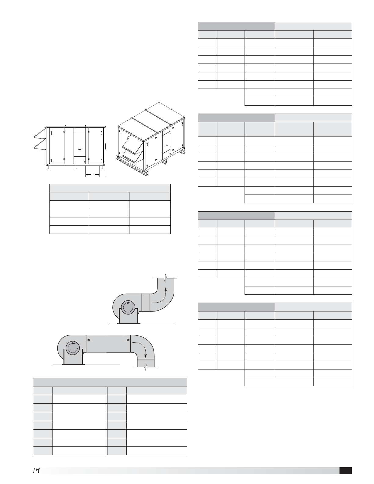
Tons
Model
ERCH-20 4, 5, 6, single stage 4, 5, 6, 7 single stage
ERCH-45 8, 10, 12.5, 15 8, 10, 11, 12.5, 14
ERCH-55 15, 17.5, 20 15, 16, 19
ERCH-90 20, 25, 30 20, 22, 24, 27, 30
Water-Source
Heat Pump
Packaged Direct
Expansion
Optional Subassemblies
Dampers
There are four locations where dampers can be
installed. Low leakage or insulated low leakage
motorized dampers can be added in the outdoor
airstream and/or return airstream. An unoccupied
recirculating air damper is also available. A backdraft
damper is standard in the exhaust hood.
Filters
There is the option of either two-inch thick MERV 8
or MERV 8 and 13 pre-filters in the outdoor airstream
and MERV 8 filters in the exhaust airstream. There are
also permanent washable aluminum mesh filters in the
optional weatherhood.
Backdraft
Permanent
Aluminum
Mesh Filters
Motorized Outdoor
Exhaust Damper
Exhaust
Weatherhood
Ooutdoor Air
Weatherhood
Air Damper
Two-inch thick MERV 8 or MERV
8 and 13 pleated filters
Two-inch thick MERV 8
pleated filters
Wheel Cassette
Filters
Motorized Return Air
Damper
Electrical Box
Return Air
Filters
Coil Section
Motorized Recirculating Air Damper
Intake
Hot Water / Chilled Water Coils
Water coils can be used for a single purpose such
as heating or cooling, or their function can be
alternated between heating and cooling by changing
the temperature of the water flowing through the coil.
Depending on the application, it may be necessary to
use a glycol mixture to prevent the liquid from freezing.
The water coils are engineered to operate at pressures
up to 250 PSIG and temperatures up to 300°F, but
ancillary equipment such as valves and pumps will often
dictate lower operating temperatures. All water coils
are pressure tested at the factory with 450 PSIG of dry
nitrogen.
Steam Coils
Steam coils are used for heating applications and are
built to operate at pressures of up to 125 PSIG with
a maximum temperature of 353°F. They are pressure
tested with 600 PSIG of dry nitrogen. The most frequent
use of steam coils is for retrofitting or modifying existing
steam heat systems.
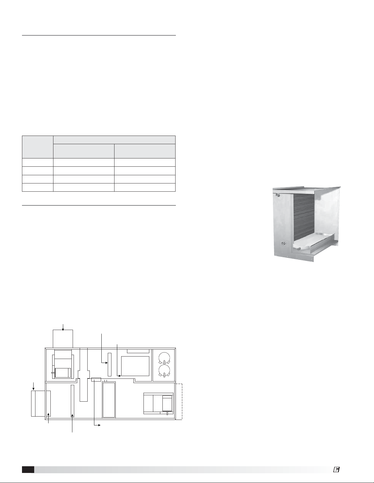
Evaporative Cooler
Evaporative cooling modules
include Munters® CELdek®
media (GLASdek® optional)
and a stainless steel frame.
Evaporative cooling media is
12 inches in depth and capable
of 90% cooling effectiveness.
A cooling module in the
exhaust airstream for indirect
evaporative cooling is
standard. For combination
indirect and direct evaporative cooling, an evaporative
section may also be added to the outdoor air stream.
Optional features include an automatic drain and fill with
freeze protection.
Packaged Direct Expansion (PDX)
The DX system comes fully charged from the factory
with refrigerant and is ready for installation upon arrival.
The smaller tonnage units (4-7 tons) contain a single
compressor, allowing for one stage of cooling. Larger
units (8-30 tons) come standard with two compressors
This allows for staging of compressors to meet a wider
range of outdoor air loads with reducing the amount of
cycles per compressor.
Integral Components
All units are provided with an expansion valve, hermetic
scroll compressor(s), liquid line filter drier, high pressure
manual reset cutout, low pressure auto-reset cutout,
time delays for compressor protection, service/charging
Indirect Gas Heater
valves, moisture indicating sight glass, and optional hot
gas bypass. The compressors also come standard with
a crankcase heater for additional protection.
General Description - NOT model specificModel ERCH Energy Recovery Ventilator
4
®
Page 5
Split DX
The unit is equipped with an evaporator coil that
will be connected to a separate condensing unit
(provided by others). Depending on controlling options,
the condensing unit will be controlled by others or
an integral unit microprocessor controller. Piping
components such as thermostatic expansion valve, filter
drier, sight glass, etc., shall be field-provided.
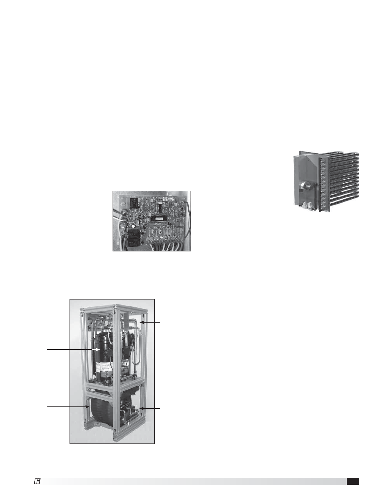
Heat Pump Module
Units with an optional, integral heat pump module
contains hermetic scroll-type compressor(s), a coaxial
refrigerant-to-water heat exchanger(s), refrigerant flow
reversing valve(s), expansion valve(s), liquid line filter
drier, high pressure manual reset cutout, crankcase
heater(s) and various sensors, service ports and safety
devices. The heat pump is intended to be connected to
an external water source such as a water cooling tower,
boiler, or a geothermal source. The module is piped
to the airside coil located in the supply airstream and
optionally to a reheat coil that will control humidity. The
location of components in the module will vary.
Control circuitry and the
Unit Protection Module
(UPM) for the heat pump
will be provided by the
factory. The UPM is a
printed circuit board and
has LED fault indicator
lights to indicate various
alarm conditions and also
power status. A unitspecific schematic for
electrical circuits is located in the control center and
another unit-specific schematic for heat pump circuitry
and UPM are located in the heat pump module.
Unit Protection Module
(UPM)
Electric Post-Heaters
The optional post-heater is used as a heat source for
the building and is integrated into the supply airstream.
A temperature sensor (with a field-adjustable set point)
is mounted in the supply airstream after the post-heater
to turn the post-heater on. A SCR heater allows for
an infinite amount of modulating control of the heat to
provide an accurate discharge temperature during the
call for heat.
As standard, the post-heater control panel is not single
point wired to the unit control center. Separate power
must be supplied to the post-heater disconnect (located
in unit control center). Electric heaters are available in
208, 230, 460, or 575 VAC (refer to heater nameplate for
voltage).
Indirect Gas Furnace
An optional indirect gas
furnace may be installed and
provides supplementary heat
to the building. Refer to the
PVF/PVG Indirect Gas-Fired
Heat manuals provided with
the unit. A unit-specific wiring
diagram is located inside the
furnace housing access door.
Outdoor Air Weatherhood
Outdoor air weatherhood will be factory-mounted.
Exhaust Air Weatherhood
The exhaust weatherhood is shipped separately as a
kit with its own instructions. Backdraft dampers are
always included as an integral part of the exhaust hood
assemblies.
High Efficiency
Scroll Type
Compressors
Coaxial
Refrigerant-
to-Water Heat
Exchangers
Refrigerant
Reversing
Valves
Water Intake
and Discharge
Connections
Heat Pump Module
General Description - NOT model specificModel ERCH Energy Recovery Ventilator®5
Page 6
Installation
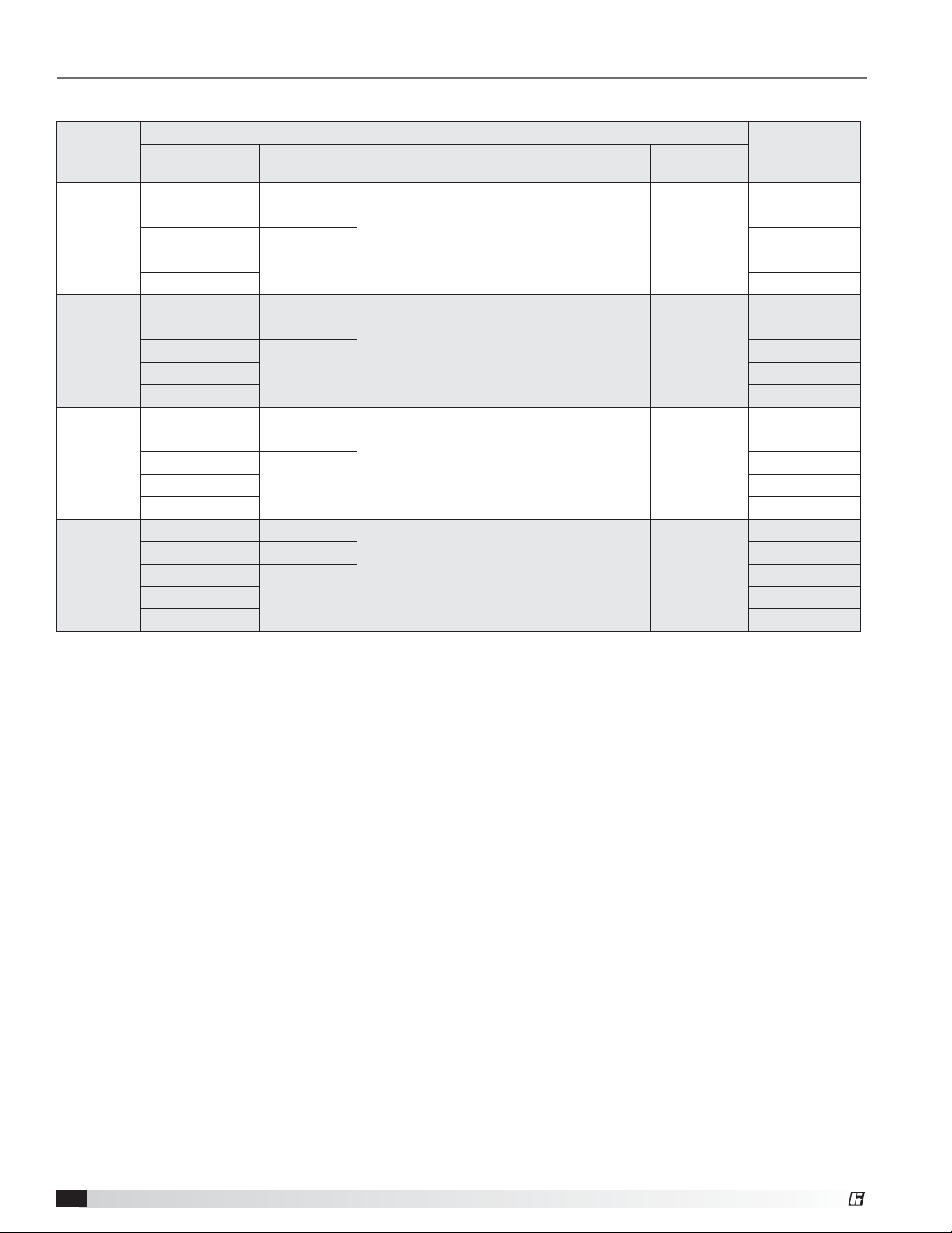
Unit Dimensions and Weights
Model
ERCH-20
ERCH-45
ERCH-55
ERCH-90
Overall Exterior Dimensions
Configuration Length Width Height
Heating Only 76.2
Exhaust
Hood
Outdoor Air
Hood
Approximate
Weight
(lbs)
1550
Cooling Coil* 96.2 1825
PDX
WSHP 2375
108.2
54.3 54.2 20.8 17.7
2350
Evap Cooling 1800
Heating Only 84.3
2325
Cooling Coil* 104.3 2725
PDX
WSHP 3775
119.3
64.4 70.2 20.7 21.7
3675
Evap Cooling 2900
Heating Only 97.5
3000
Cooling Coil* 116.5 3475
PDX
WSHP 4725
133.5
75.2 71 23.6 21.7
4125
Evap Cooling 3325
Heating Only 109.5
4300
Cooling Coil* 129.5 5050
PDX
WSHP 6450
151.5
94.5 89 25.5 26.7
6325
Evap Cooling 5400
*With or without heat.
PDX = Packaged Direct Expansion
WSHP = Water-Source Heat Pump
All dimensions are in inches. Unit weights assume rooftop configuration with weatherhood, filters, outdoor air damper and
heating or cooling options (where applicable) including but not limited to: a six row dx coil, integral condensing section and
an indirect gas-fired furnace. The approximate weight (lbs) is assuming all possible accessories are added per housing and
may vary by 10% depending on unit.
General Description - NOT model specificModel ERCH Energy Recovery Ventilator
6
®
Page 7
Installation
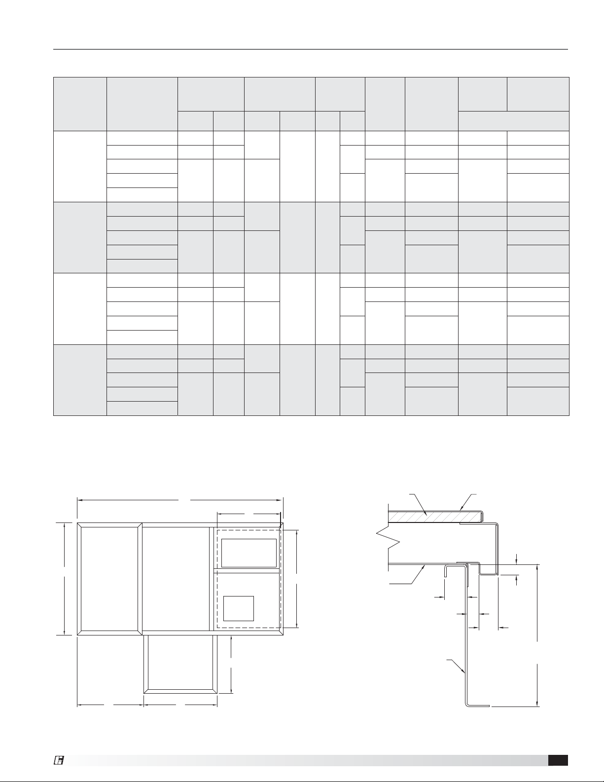
Curb Outside Dimensions, Recommended Roof Openings and Curb Weights
Model Configuration
Heating Only 71.8 49.9
Cooling Coil* 91.8 49.9
ERCH-20
PDX
WSHP
Evap Cooling
Heating Only 79.9 60
Cooling Coil* 99.9 60
ERCH-45
PDX
WSHP
Evap Cooling
Heating Only 93.1 70.8
Cooling Coil* 112.1 70.8
ERCH-55
PDX
WSHP
Evap Cooling
Heating Only 105.1 90.1
Cooling Coil* 112.1 70.8
ERCH-90
PDX
WSHP
Evap Cooling
Outside
Curb
Dimensions
Length Width A B C D
103.8 49.9 40.7 166
114.9 60 44.5 195
129.1 70.8 58.6 228
147.1 90.1 61.4 291
Recommended
Roof
Openings
28.6
45.2 30
29.5
55.3 35.1
40.6
66 41.8
41.4
85.4 51.1
Optional
Piping
Vestibule
12 inch
Curb
Weight
16.6 134 157 +6.9 +8.3
37
147 179 +7.7 +9.5
NA NA NA
16.6 157 180 +8.0 +9.4
37
170 202 +8.8 +10.6
NA NA NA
16.6 184 207 +9.3 +10.7
37
196 228 +10.1 +11.9
NA NA NA
16.6 231 254 +11.2 +12.6
37
196 228 +12 +13.8
NA NA NA
12 inch
Curb
Weight
with Piping
Vestibule
199
228
260
323
Curb
weight
only
Adder per inch
+8.3
+9.5
+10.9
+13.1
Curb Weight
with Piping
Vestibule
+10.1
+11.4
+12.7
+14.9
*With or without heating.
PDX = Packaged Direct Expansion
WSHP = Water-Source Heat Pump
All dimensions are in inches. All weights are in pounds. Various curb heights are available, use the adder per inch column to
determine the weights above 12 inches.
L
A
RETURN AIR INTAKE
W
SUPPLY AIR
DISCHARGE
OPTIONAL
PIPING VESTIBULE
C D
26.1 inches
B
1-inch Foam Insulation
Curb Duct
Adaptor
1.9 inches
1/2 inch
Curb
Unit Base
1.63
inches
1 inch
Curb
Height
Curb Cap Details for Factory-Supplied Roof Curbs
General Description - NOT model specificModel ERCH Energy Recovery Ventilator®7
Page 8
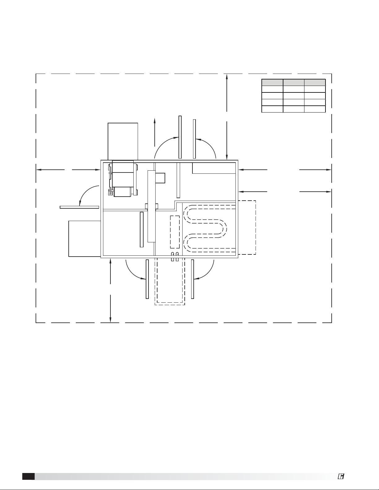
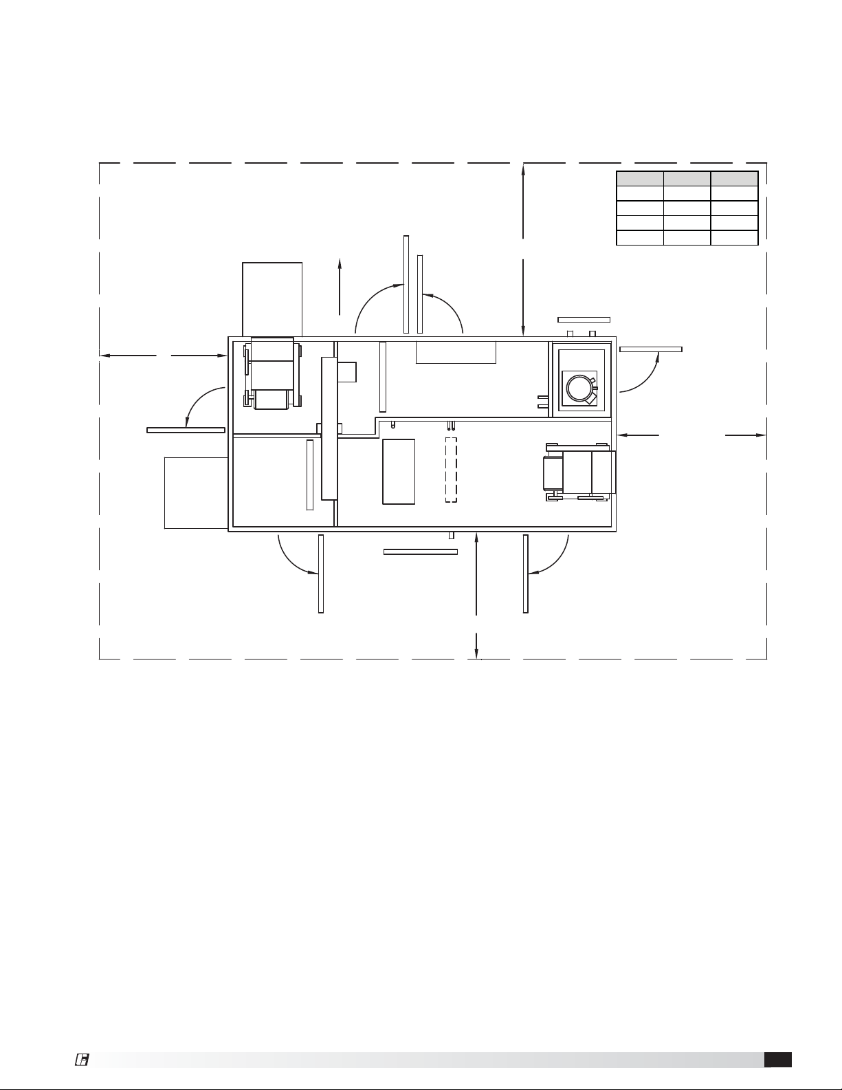
Service Clearances / Access Panel - Heating Only
Units require minimum clearances for access on all sides for routine maintenance. Filter replacement, drain pan
inspection and cleaning, energy wheel cassette inspection, fan bearing lubrication and belt adjustment are examples
of routine maintenance that must be performed. Blower and motor assemblies, energy recovery wheel cassette, coil
and filter sections are always provided with a service door or panel for proper component access.
*Cassette removal only available
on housing sizes 20 and 45.
B
ACCESS DOOR
OUTDOOR
WEATHERHOOD
EXHAUST AIR
WEATHERHOOD
OUTDOOR AIR FILTERS
*CASSETTE REMOVAL
WHEEL CASSETTE
ACCESS DOOR
EXHAUST FILTERS
HEATING COIL
ACCESS DOOR
ELECTRICAL BOX
Model A (in.) B (in.)
ERCH-20 48 36
ERCH-45 64 42
ERCH-55 42 42
ERCH-90 42 48
A
52 inches
CLEARANCE WITH
IG HEATER
0 inches
CLEARANCE WITHOUT
IG HEATER
INDIRECT GAS FURNACE
36 inches
ACCESS DOOR
PIPING VESTIBULE
(OPTIONAL)
ACCESS DOOR
Drawing shows both heating coil and indirect gas furnace options. Electric heat is also available. Only one can
be selected.
General Description - NOT model specificModel ERCH Energy Recovery Ventilator
8
®
Page 9
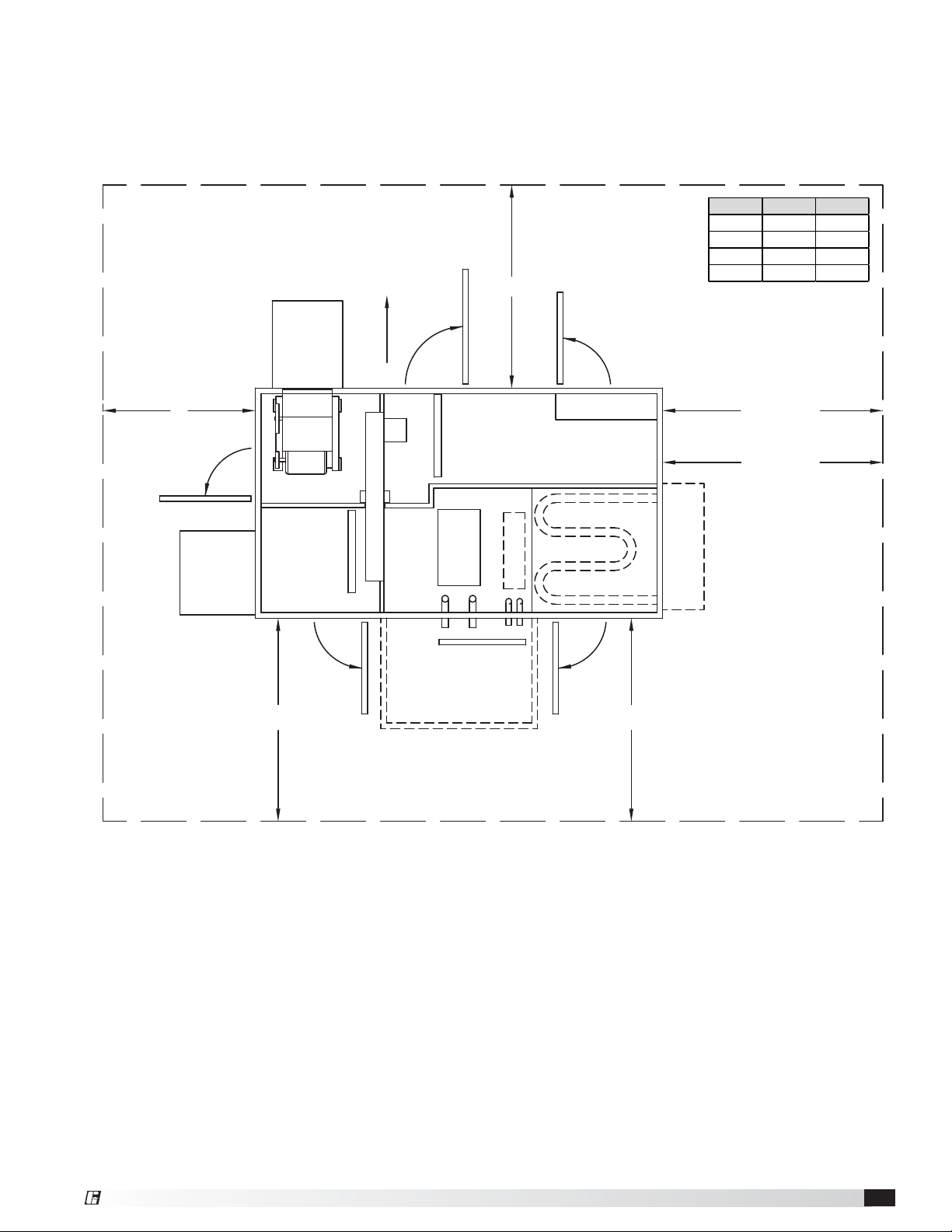
Service Clearances / Access Panel - Cooling Coil (with or without heating)
Units require minimum clearances for access on all sides for routine maintenance. Filter replacement, drain pan
inspection and cleaning, energy wheel cassette inspection, fan bearing lubrication and belt adjustment are examples
of routine maintenance that must be performed. Blower and motor assemblies, energy recovery wheel cassette, coil
and filter sections are always provided with a service door or panel for proper component access.
*Cassette removal only available
on housing sizes 20 and 45.
B
ACCESS DOOR
OUTDOOR
WEATHERHOOD
EXHAUST AIR
WEATHERHOOD
OUTDOOR AIR FILTERS
*CASSETTE REMOVAL
WHEEL CASSETTE
ACCESS DOOR
EXHAUST FILTERS
COOLING COIL
ACCESS PANEL
A
HEATING COIL
ACCESS DOOR
ELECTRICAL BOX
Model A (in.) B (in.)
ERCH-20 48 36
ERCH-45 64 42
ERCH-55 42 42
ERCH-90 42 48
52 inches
CLEARANCE WITH
IG HEATER
0 inches
CLEARANCE WITHOUT
IG HEATER
INDIRECT GAS FURNACE
ACCESS DOOR
48 inches
CLEARANCE
WITH
VESTIBULE
36 inches
CLEARANCE
WITHOUT
VESTIBULE
ACCESS DOOR
PIPING VESTIBULE
(OPTIONAL)
Drawing shows both heating coil and indirect gas furnace options. Only one can be selected.
General Description - NOT model specificModel ERCH Energy Recovery Ventilator®9
Page 10
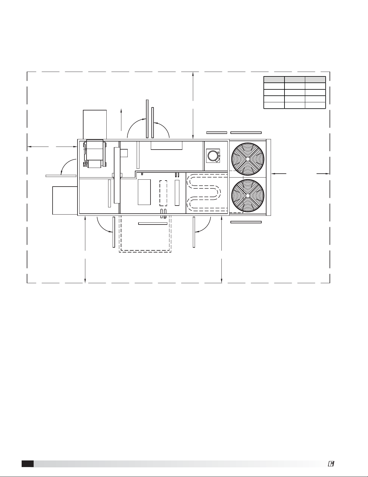
Service Clearances / Access Panel - Integral Air-Cooled Packaged DX
Units require minimum clearances for access on all sides for routine maintenance. Filter replacement, drain pan
inspection and cleaning, energy wheel cassette inspection, fan bearing lubrication and belt adjustment are examples
of routine maintenance that must be performed. Blower and motor assemblies, energy recovery wheel cassette, coil
and filter sections are always provided with a service door or panel for proper component access.
*Cassette removal only available
on housing sizes 20 and 45.
EXHAUST AIR
WEATHERHOOD
B
ACCESS DOOR
OUTDOOR
WEATHERHOOD
OUTDOOR AIR FILTERS
*CASSETTE REMOVAL
WHEEL CASSETTE
ACCESS DOOR
ACCESS DOORS
ELECTRICAL BOX
EXHAUST FILTERS
COOLING COIL
ACCESS PANEL
HEATING COIL
HGRH COIL
A
ACCESS DOOR
ACCESS PANEL
ACCESS PANEL
COMPRESSORS
ACCESS PANEL
Model A (in.) B (in.)
ERCH-20 48 36
ERCH-45 64 42
ERCH-55 42 42
ERCH-90 42 48
42 inches
MINIMUM
CONDENSING SECTION
36 inches
CLEARANCE
WITHOUT
VESTIBULE
PIPING VESTIBULE
(OPTIONAL)
48 inches
CLEARANCE
WITH
VESTIBULE
Drawing shows both heating coil and indirect gas furnace options. Electric heat is also available. Only one can
be selected. Optional hot gas reheat coil also shown, available with split or packaged DX.
General Description - NOT model specificModel ERCH Energy Recovery Ventilator
10
®
Page 11
Service Clearances / Access Panel - Water-Source Heat Pump
Units require minimum clearances for access on all sides for routine maintenance. Filter replacement, drain pan
inspection and cleaning, energy wheel cassette inspection, fan bearing lubrication and belt adjustment are examples
of routine maintenance that must be performed. Blower and motor assemblies, energy recovery wheel cassette, coil
and filter sections are always provided with a service door or panel for proper component access.
*Cassette removal only available
on housing sizes 20 and 45.
B
ACCESS DOOR
OUTDOOR
WEATHERHOOD
EXHAUST AIR
WEATHERHOOD
OUTDOOR AIR FILTERS
*CASSETTE REMOVAL
WHEEL CASSETTE
ACCESS DOORS
ELECTRICAL BOX
EXHAUST FILTERS
HEATING AND
COOLING COIL
ACCESS PANEL
Model A (in.) B (in.)
ERCH-20 48 36
ERCH-45 64 42
ERCH-55 42 42
ERCH-90 42 48
A
ACCESS PANEL
ACCESS DOOR
HEAT PUMP
42 inches
HGRH COIL
ACCESS DOOR
Drawing shows optional hot gas reheat coil.
ACCESS DOOR
36 inches
General Description - NOT model specificModel ERCH Energy Recovery Ventilator®11
Page 12
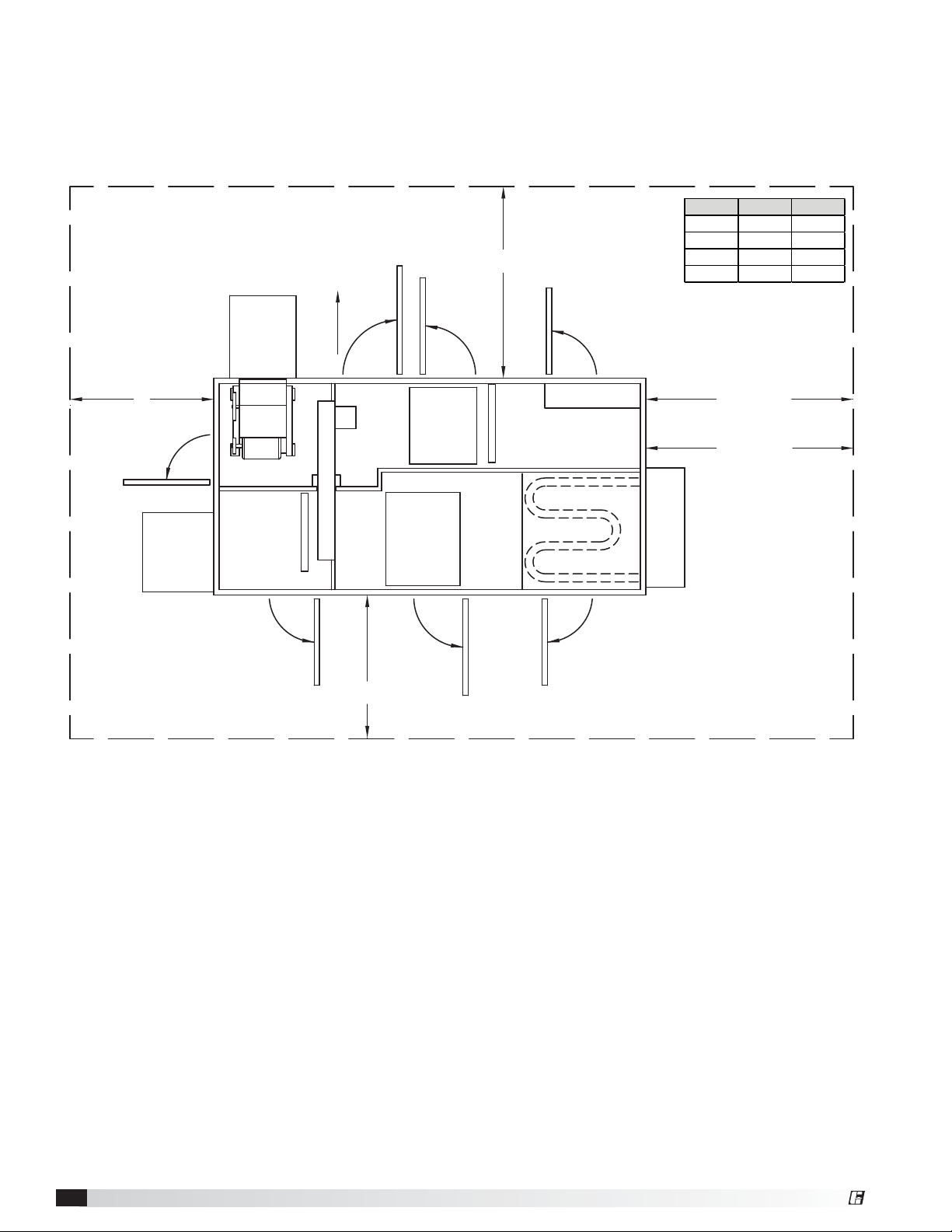
Service Clearances / Access Panel - Evaporative Cooling
Units require minimum clearances for access on all sides for routine maintenance. Filter replacement, drain pan
inspection and cleaning, energy wheel cassette inspection, fan bearing lubrication and belt adjustment are examples
of routine maintenance that must be performed. Blower and motor assemblies, energy recovery wheel cassette, coil
and filter sections are always provided with a service door or panel for proper component access.
*Cassette removal only available
on housing sizes 20 and 45.
B
ACCESS DOOR
OUTDOOR
WEATHERHOOD
EXHAUST AIR
WEATHERHOOD
OUTDOOR AIR FILTERS
*CASSETTE REMOVAL
WHEEL CASSETTE
ACCESS DOORS
INDIRECT
EVAP
DIRECT
EVAP
Model A (in.) B (in.)
ERCH-20 48 36
ERCH-45 64 42
A
ACCESS DOOR
ELECTRICAL BOX
EXHAUST FILTERS
ERCH-55 42 42
ERCH-90 42 48
52 inches
CLEARANCE WITH
IG HEATER
0 inches
CLEARANCE WITHOUT
IG HEATER
INDIRECT GAS FURNACE
ACCESS DOOR
ACCESS DOOR
ACCESS DOOR
36 inches
Drawing shows optional indirect gas furnace. Electric heat is also available. Only one can be selected.
General Description - NOT model specificModel ERCH Energy Recovery Ventilator
12
®
Page 13
Handling
While this unit was constructed with quality and
dependability in mind, damage still may occur during
handling of the unit for installation. Exercise extreme
caution to prevent any damage from occurring to the
refrigerant system. This unit could contain a system
pressurized with refrigerant that, if damaged, could
leak into the atmosphere or cause bodily harm due to
the extreme cold nature of expanding refrigerant. Use
protective equipment such as gloves and safety glasses
to minimize or prevent injury in case of a system leak
during installation.
The system design and installation should follow
accepted industry practice, such as described in
the ASHRAE Handbook. Adequate space should be
left around the unit for piping coils and drains, filter
replacement, and maintenance. Sufficient space should
be provided on the side of the unit for routine service
and component removal should that become necessary.
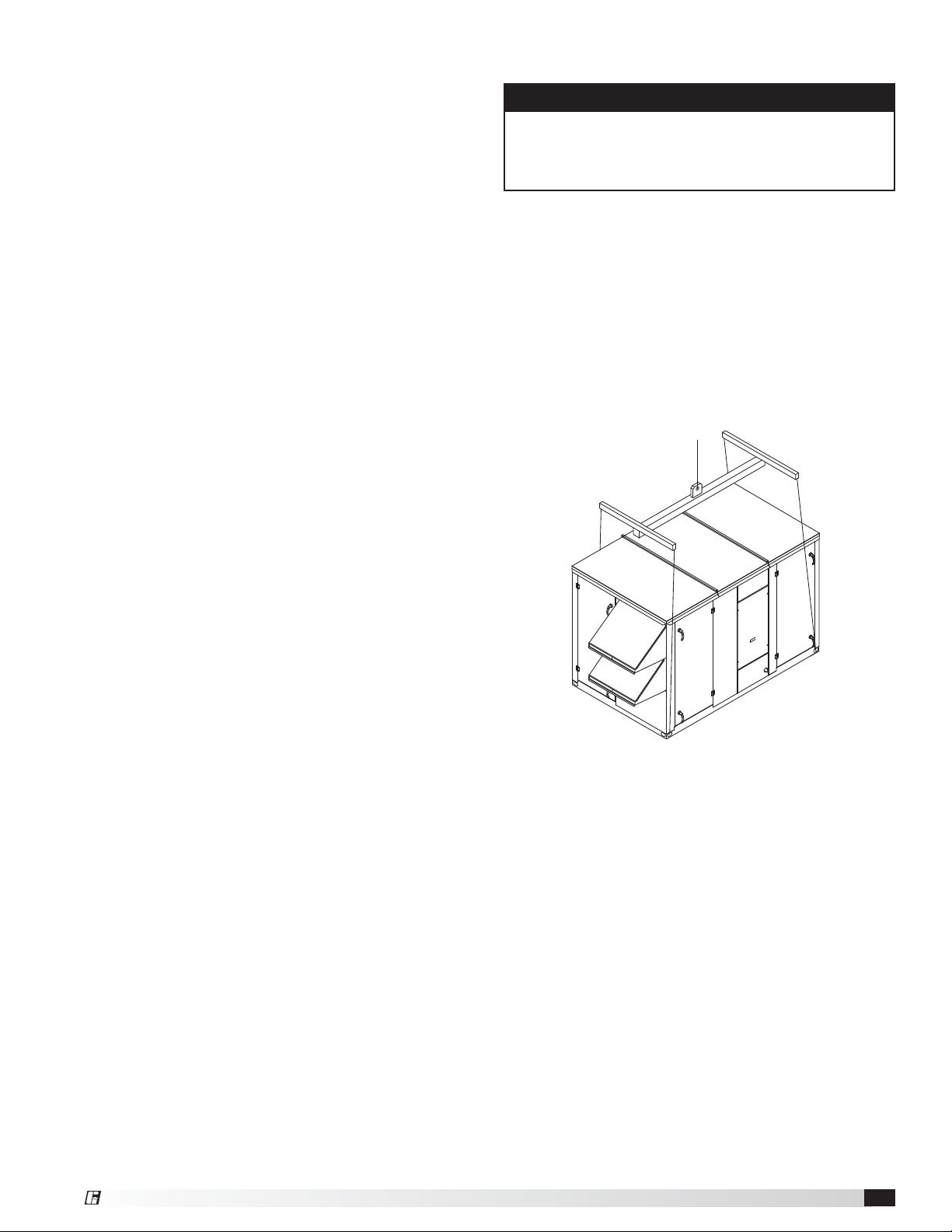
Lifting
WARNING
All factory-provided lifting lugs must be used when
lifting the units. Failure to comply with this safety
precaution could result in property damage, serious
injury, or death.
1. Before lifting, be sure that all shipping material has
been removed from unit.
2. To assist in determining rigging requirements,
weights are provided in the Installation, Unit
Dimensions and Weights section of this manual.
3. Unit must be lifted by all lifting lugs provided on
base structure.
4. Rigger to use suitable mating hardware to attach to
unit lifting lugs.
5. Spreader bar(s) must span the unit to prevent
damage to the cabinet by the lift cables.
6. Always test-lift the unit to check for proper balance
and rigging before hoisting to desired location.
7. Never lift units by weatherhoods.
8. Never lift units in windy conditions.
9. Preparation of curb and roof openings should be
completed prior to lifting unit to the roof.
10. Check to be sure that gasketing (supplied by
others) has been applied to the curb prior to lifting
the unit and setting on curb.
11. Do not use fork lifts for handling unit.
General Description - NOT model specificModel ERCH Energy Recovery Ventilator®13
Page 14
Roof Curb Mounting
Rooftop units require curbs to be mounted first. The
duct connections must be located so they will be clear
of structural members of the building.
Position the unit roof opening such that the supply
discharge and exhaust inlet of the unit will line up with
the corresponding ductwork. Be sure to allow for the
recommended service clearances when positioning
opening.
Do not face the outdoor air intake of the unit into
prevailing wind and keep the intake away from any other
exhaust fans. Likewise, position the exhaust discharge
opening away from outdoor air intakes of any other
equipment.
1. Factory-Supplied Roof Curbs: Roof curbs are
Model GKD, which are shipped in a knockdown kit
(includes duct adapter) and require field assembly
(by others). Assembly instructions are included with
the curb.
2. Install Curb: Locate curb over
roof opening and fasten
in place. Reference
Installation, Curb
Outside Dimensions,
Recommended
Roof Openings
and Weights in this
manual. Check
that the diagonal
dimensions are within
±1/8 inch of each
other and adjust as
necessary. For proper
coil drainage and
unit operation, it is
important that the
installation be level.
Shim as required to
level.
3. Install Ductwork: Installation of all ducts should
be done in accordance with SMACNA and AMCA
guidelines. Duct adapter provided to support ducts
prior to setting the unit.
4. Set the Unit: Lift unit to a point directly above the
curb and duct openings. Guide unit while lowering
to align with duct openings. Roof curbs fit inside the
unit base. Make sure the unit is properly seated on
the curb and is level. Gasketing (by others) needs
to be installed to curb creating a seal between the
ductwork and the base of the unit.
5. Install Vestibule: If unit was ordered with a vestibule
and it has not yet been attached to the unit, caulk
and attach the vestibule at this time.
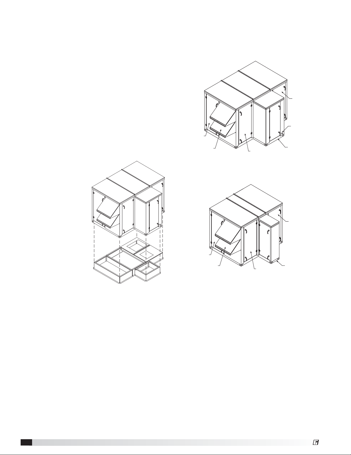
Optional Piping Vestibule
Insulated enclosure that is mounted externally to the
unit in order to protect the water supply and return
piping. Not available in models with water-source heat
pump or evaporative cooling.
Supply Blower
Access Door
Drain Pan
Connection
Exhaust Blower
Access Door
Outdoor Air
Weatherhood
Cassette/Filter
Access Door
Cooling Coil (with or without heating) or PDX
Exhaust Blower
Access Door
Outdoor Air
Weatherhood
Cassette/Filter
Access Door
Heating Only
Piping
Vestibule
Supply Blower
Access Door
Piping
Vestibule
General Description - NOT model specificModel ERCH Energy Recovery Ventilator
14
®
Page 15
R
o
t
a
t
i
o
n
POOR
Rail Mounting / Layout
1. Rails designed to handle the weight of the unit
should be positioned as shown on the diagram (rails
by others).
2. Make sure that rail positioning does not interfere with
the supply air discharge opening or the exhaust air
intake opening on the unit. Avoid area dimensioned
“B” below.
3. Rails should run the width of the unit and extend
beyond the unit a minimum of 12 inches on each
side.
ERCH-20 Recommended Duct Size
Intake Duct Size Discharge 9-9 Blower 10-6 Blower
OIE 22 x 26 SDE 16 x 16 16 x 16
OIT 24 x 20 SDS 16 x 16 16 x 16
RIE 16 x 32 SDT 16 x 16 16 x 16
RIS 18 x 30 SDT/IG 28 x 24 28 x 24
RIB 16 x 32 SDB 12 x 14 12 x 14
RIT 16 x 32 EDE 16 x 16 16 x 16
EDT 16 x 16 16 x 16
EDS 16 x 16 16 x 16
4. Set unit on rails.
ERCH-45 Recommended Duct Size
Intake Duct Size Discharge
12-8 Blower
12-12 Blower
9-9 Blower
OIE 28 x 36 SDE 20 x 20 16 x 16
OIT 34 x 24 SDS 20 x 20 16 x 16
RIE 24 x 40 SDT 20 x 20 16 x 16
RIS 26 x 32 SDT/IG 28 x 28 28 x 28
BA
RIB 20 x 48 SDB 16 x 18 16 x 18
RIT 28 x 30 EDE 20 x 20 16 x 16
Rail Mounting
Unit Size A B
EDT 20 x 20 16 x 16
EDS 20 x 20 16 x 16
ERCH-20 5.0 41.0
ERCH-45 7.0 41.9
ERCH-55 5.5 53.0
ERCH-90 6.0 59.0
All dimensions are in inches.
ERCH-55 Recommended Duct Size
Intake Duct Size Discharge 12-12 Blower 15-15 Blower
OIE 32 x 52 SDE 20 x 20 28 x 28
OIT 40 x 28 SDS 20 x 20 28 x 28
RIE 30 x 40 SDT 20 x 20 28 x 28
Ductwork Connections
Examples of poor and good fan-to-duct connections
are shown. Airflow out of the fan should
be directed straight or curve the
same direction as the
RIS 30 x 38 SDT/IG 38 x 30 38 x 30
RIB 20 x 54 SDB 16 x 18 18 x 20
RIT 30 x 40 EDE 20 x 20 28 x 28
EDT 20 x 20 28 x 28
EDS 20 x 20 28 x 28
fan wheel rotates. Poor
duct installation will result
in low airflow and other
system effects.
n
o
i
t
a
t
o
R
Length of Straight Duct
GOOD
Inlet/Outlet Descriptions
Code Description Code Description
OIE Outdoor Air Intake End SDT Supply Discharge Top
OIT Outdoor Air Intake Top SDT/IG Supply Discharge Top w/IG
RIE Return Air Intake End SDS Supply Discharge Side
RIS Return Air Intake Side SDB Supply Discharge Bottom
RIB Return Air Intake Bottom EDE Exhaust Discharge End
ERCH-90 Recommended Duct Size
Intake Duct Size Discharge 15-15 Blower 18-18 Blower
OIE 34 x 64 SDE 28 x 28 32 x 32
OIT 34 x 50 SDS 28 x 28 32 x 32
RIE 32 x 60 SDT 28 x 28 32 x 32
RIS 40 x 40 SDT/IG 34 x 34 34 x 33
RIB 22 x 74 SDB 18 x 20 20 x 24
RIT 40 x 40 EDE 28 x 28 32 x 32
EDT 28 x 28 32 x 32
EDS 28 x 28 32 x 32
All dimensions shown in inches.
• Recommended duct sizes are based on velocities across the cfm
range of each model at approximately 800 feet per minute (FPM) at
minimum airflow and up to 1600 fpm at maximum airflow.
• Recommended duct sizes are only intended to be a guide and
may not satisfy the requirements of the project. Refer to plans for
appropriate job specific duct size and/or velocity limitations.
RIT Return Air Intake Top EDT Exhaust Discharge Top
SDE Supply Discharge End EDS Exhaust Out Side
General Description - NOT model specificModel ERCH Energy Recovery Ventilator®15
Page 16
Electrical Installation
WARNING
The roof lining contains high voltage wiring. To prevent
electrocution, do not puncture the interior or exterior
panels of the roof.
WARNING
To prevent injury or death due to electrocution or
contact with moving parts, lock disconnect switch
open.
For units with a gas furnace, if you turn off the power
supply, turn off the gas.
IMPORTANT
Before connecting power to the unit, read and
understand the following instructions and wiring
diagrams. Complete wiring diagrams are attached on
the inside of the control center door(s).
IMPORTANT
All wiring should be done in accordance with the latest
edition of the National Electrical Code ANSI/NFPA70
and any local codes that may apply. In Canada, wiring
should be done in accordance with the Canadian
Electrical Code.
IMPORTANT
The equipment must be properly grounded and
bonded. Any wiring running through the unit in the
airstream must be protected by metal conduit, metal
clad cable or raceways.
CAUTION
If replacement wire is required, it must have a
temperature rating of at least 105°C, except for an
energy cut-off or sensor lead wire which must be rated
to 150°C.
DANGER
High voltage electrical input is needed for this
equipment. This work should be performed by a
qualified electrician.
CAUTION
Any wiring deviations may result in personal injury or
property damage. Manufacturer is not responsible
for any damage to, or failure of the unit caused by
incorrect final wiring.
WARNING
If unit is equipped with a microprocessor, terminals
Y1, Y2 and W1 cannot be wired to a thermostat.
Wiring to these terminals will bypass unit’s internal
safeties.
1. Determine the Size of the Main Power Lines
The unit’s nameplate states the voltage and the unit’s
MCA. The main power lines to the unit should be
sized accordingly. The nameplate is located on the
outside of the unit on the control panel side.
2. Determine the Size of Electric Heater Wiring
An optional electric heater may require a separate
power supply. The power connection should
be made to the factory-provided electric heater
disconnect and must be compatible with the ratings
on the nameplate, supply power voltage, phase and
amperage. Consult ANSI/NFPA 70 and CSA C22.1
for proper conductor sizing.
3. Provide the Opening(s) for the Electrical
Connections
Electrical openings vary by unit size and arrangement
and are field-supplied.
4. Connect the Power Supplies
Connect the main power lines and electric heater
power lines to the disconnect switches or terminal
blocks and main grounding lug(s). Torque field
connections to manufacturer’s recommendations.
5. Wire the Optional Convenience Outlet
The convenience outlet requires a separate 115V
power supply circuit. The circuit must include short
circuit protection which may need to be supplied by
others.
6. Connect Field-Wired Low Voltage Components
Most factory-supplied electrical components are
prewired. To determine what electrical accessories
require additional field-wiring, refer to the unitspecific wiring diagram located on the inside of the
control center access door.
If unit is equipped with a microprocessor, terminals Y1,
Y2 and W1 cannot be wired to a thermostat. Wiring to
these terminals will bypass unit’s internal safeties.
Control wires should not be run inside the same conduit
as that carrying the supply power. Make sure that
field-supplied conduit does not interfere with access
panel operation. All low voltage wiring should be run in
conduit wherever it may be exposed to the weather.
The low voltage control circuit is 24 VAC and control
wiring should not exceed 0.75 ohms. If wire resistance
exceeds 0.75 ohms, an isolation relay should be added
to the unit control center and wired in place of the
remote switch (typically between terminal blocks R
and G on the terminal strip. The relay must be rated
for at least 5 amps and have a 24 VAC coil. Failure to
comply with these guidelines may cause motor starters
to “chatter” or not pull in which can cause contactor
failures and/or motor failures.
General Description - NOT model specificModel ERCH Energy Recovery Ventilator
16
®
Page 17
Field-Provided Disconnect
If field-installing an additional disconnect switch, it
is recommended that there is at least four feet of
service room between the switch and system access
panels. When providing or replacing fuses in a fusible
disconnect, use dual element time delay fuses and size
according to the rating plate.
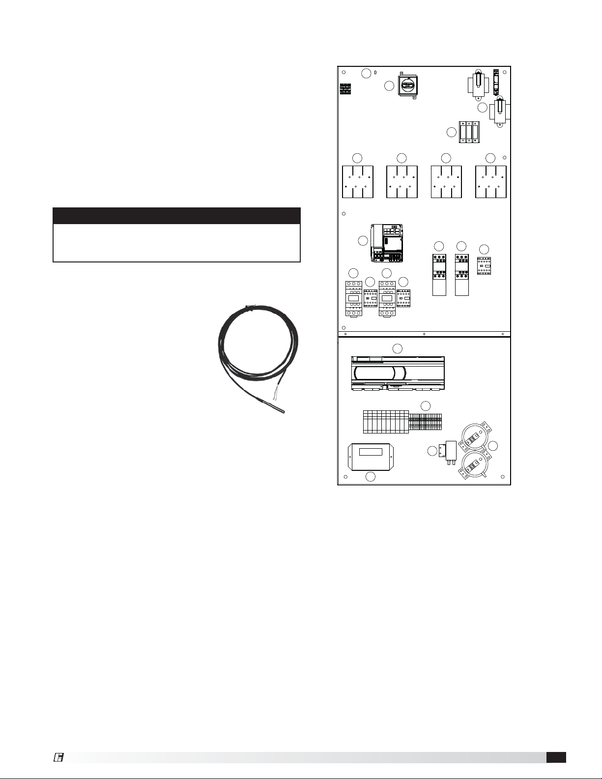
Typical Control Center Components with
Microprocessor Control
8
1
5
Discharge Air Temperature Sensor
Without Indirect Gas Furnace
For units without an indirect gas furnace, the discharge
air temperature sensor is factory-mounted in the blower
discharge section of the unit behind the blower cut off
plate.
WARNING
Discharge air temperature sensor is to be fieldinstalled prior to unit start-up on units with an indirect
gas furnace.
With Indirect Gas Furnace
For units with an indirect gas furnace, the discharge
air temperature sensor is to be
field-installed prior to unit start
up at least three duct diameters
downstream of the heat exchanger
or where good mixed average
temperature occurs in the ductwork.
The discharge air sensor is shipped
loose and can be found in the unit’s
control center. See the unit-specific
wiring diagram for connection locations.
10 10
15
16 16
17
9
7 7
2
3
17
11
6
4
14
13
12
Individual components and locations will vary.
1. Main disconnect (non-fusible, lockable)
2. Motor starter - outdoor air fan
3. Motor starter - exhaust air fan
4. Motor contactor - energy wheel
5. 24 VAC control transformer
6. 24 VAC terminal strip
7. Fuses for blower motors
8. Grounding lug
9. Distribution block
10. Compressor fuse blocks
Optional Components
11. Microprocessor controller
12. Dirty filter pressure switches
13. GreenTrol®
14. Frost control pressure switch
15. Energy recovery wheel VFD
16. Compressor contactors
17. Condenser fan contactors
General Description - NOT model specificModel ERCH Energy Recovery Ventilator®17
Page 18

Optional Accessory Wiring Schematics
Remote Panel
The remote panel is available with a number of different
alarm lights and switches to control the unit. The remote
panel ships loose and requires mounting and wiring in
the field. The remote panel is available with the following
options:
• Unit on/off switch
• Unit on/off light
• 7-day time clock
• Hand/off/auto switch
• Dirty filter light
• Economizer light
• Frost control light
• Wheel rotation sensor light
Unit Interfacing Terminals
Heating/Cooling Switches and Night Setback Switch/
Timer
TERMINAL BLOCKS IN
UNIT CONTROL CENTER
R
UNIT ON/OFF
S1
COOL STAGE 1 / ECONOMIZER
S6
COOL STAGE 2
S7
HEAT
S4
C
G
Y1
Y2
W1
6
7
12
7-Day Timer
TERMINAL BLOCKS IN
UNIT CONTROL CENTER
R
BLACK BLUE
RED
(CAPPED)
TIMER
C
G
Y1
Y2
W1
6
7
12
On/Off/Auto Switch & Indictor Light Wiring
TERMINAL BLOCKS IN
UNIT CONTROL CENTER
UNIT ON/OFF
FROST CONTROL
ECONOMIZER
WHEEL ROTATION
ON
OFF
AUTO
* -- BMS, TIMECLOCK,
TSTAT, RTU, ETC.
*
R
C
G
Y1
Y2
W1
6
7
12
UNOCCUPIED RECIRCULATION
S5
Dirty Filter Indicator
(Powered by others)
SUPPLY DIRTY
FILTER SWITCH
EXHAUST DIRTY
FILTER SWITCH
NC
NC
HOT COMMON
C
C
A
NO
NO
DIRTY FILTER
C
SUPPLY DIRTY
FILTER SWITCH
EXHAUST DIRTY
FILTER SWITCH
ON/OFF/AUTO SWITCH ALLOWS THREE MODES OF OPERATION
"ON" - UNIT IS TURNED ON MANUALLY
"OFF" - UNIT IS TURNED OFF MANUALLY
"AUTO" - UNIT IS CONTROLLED VIA SCHEDULER OF BMS, TIMECLOCK, TSAT, ETC.
General Description - NOT model specificModel ERCH Energy Recovery Ventilator
18
NC
NC
NO
C
NO
DIRTY FILTER
®
Page 19

Piping Installation
Optional Gas Piping
Units with indirect gas-fired furnaces require fieldsupplied and installed gas supply piping. The unit gas
connection is
pressure is 14 in. wg.
From Gas Supply
Gas Connections
If this unit is equipped with an indirect gas-fired furnace,
connection to an appropriate gas supply line will be
required. For complete information on installation
procedures for the optional gas furnace, refer the
PVF/PVG Indirect Gas-Fired Heat Module Installation,
Operation, and Maintenance Manual.
Optional Coil Piping
Factory-installed cooling and heating components are
mounted in the coil section of the unit. The coil section
is downstream of the energy wheel on the supply air
side of the unit. Note the coil connection locations on
the picture. Coil connections are located external to the
unit as shown.
Note: DX coil liquid connection is internal to units.
Water Coils
3
⁄4 inch NPT. The maximum allowable gas
Ground
Joint
Gas Cock
Bleeder Valve or
1/8 in Plugged Tap
Typical Gas Supply Piping Connection
Water coil
connections
Union
connection
8 in. Trap
DX coil
liquid
access
door
Gas to
Controls
2. Connect the water supply to the bottom connection
on the air leaving side and the water return to the
top connection on the air entering side. Connecting
the supply and/or return in any other manner will
result in very poor performance. Be sure to replace
factory-installed grommets around coil connections
if removed for piping. Failure to replace grommets
will result in water leakage into the unit and altered
performance.
3. Water coils are not normally recommended for
use with entering air temperatures below 40°F. No
control system can be depended on to be 100% safe
against freeze-up with water coils. Glycol solutions
or brines are the only safe media for operation of
water coils with low entering air conditions. If glycol
or brine solutions are not used, coils must be drained
when freezing conditions are expected. If required,
vent and drain connections must be fieldpiped, external to the unit.
4. Pipe sizes for the system must be selected on
the basis of the head (pressure) available from the
circulation pump. The velocity should not exceed
6 feet per second and the friction loss should be
approximately 3 feet of water column per 100 feet
of pipe.
5. For chilled water coils, the condensate drain
pipe should be sized adequately to ensure the
condensate drains properly. Refer to Drain Trap
section.
Direct Expansion (DX) Coils (Split DX)
1. Piping should be in accordance with accepted
industry standards. Pipework should be supported
independently of the coils. Undue stress should not
be applied at the connection to coil headers.
2. The condensate drain pipe should be sized
adequately to ensure the condensate drains properly.
Refer to Condensate Drain Trap section.
3. When connecting suction and liquid connections
make sure the coil is free from all foreign material.
Make sure all joints are tight and free of leakage. Be
sure to replace factory-installed grommets around
coil connections if removed for piping.
4. Manufacturer does not supply compressor or
condensing units with standard models. For further
instruction on DX coil installation and operation
contact your compressor and/or condenser
manufacturer.
1. Piping should be in accordance with accepted
industry standards. Pipework should be supported
independently of the coils. When installing couplings,
do not apply undue stress to the connection
extending through the unit. Use a backup pipe
wrench to avoid breaking the weld between coil
connection and header.
General Description - NOT model specificModel ERCH Energy Recovery Ventilator®19
Page 20

Condensate Drain Trap
This unit is equipped with a stainless steel condensate
pan with a 1-inch MPT stainless steel drain connection.
It is important that the drain connection be fitted with a
P trap to ensure proper drainage of condensate while
maintaining internal static pressures.
A P trap assembly (kit) is
supplied with each unit and is
to be assembled and installed
as local conditions require and
according to the assembly
instructions provided with the
P trap. If local and area codes
permit, the condensate may
be drained back onto the roof,
but a drip pad should be provided beneath the outlet.
If local and area codes require a permanent drain line,
it should be fabricated and installed in accordance with
Best Practices and all codes.
In some climates, it will be necessary to provide freeze
protection for the P trap and drain line. The P trap
should be kept filled with water or glycol solution at
all times and it should be protected from freezing to
protect the P trap from damage. If severe weather
conditions occur, it may be necessary to fabricate a P
trap and drain line of metal and install a heat tape to
prevent freezing.
Heat Pump Piping Sizes and Connections
Pipe Size
(in. FPT)
1
1.25
1.5
2
Model Tonnage
ERCH-20 4 2
ERCH-45 8 2
ERCH-20 5 2
ERCH-45 10 2
ERCH-20 6 2
ERCH-45
ERCH-55 15 2
ERCH-55
ERCH-90
12.5 2
15 2
17.5 2
20 2
20 2
25 2
30 2
Number of
Connections
General Description - NOT model specificModel ERCH Energy Recovery Ventilator
20
®
Page 21

Optional Evaporative Cooler
CAUTION
All solenoids valves and traps must be installed below the
roof to protect the supply water line from freezing. If they
cannot be installed below the roof, an alternative method
must be used to protect the lines from freezing.
IMPORTANT
The supply line should be of adequate size and
pressure to resupply the amount of water lost due to
bleed-off and evaporation. The drain line should be
the same size or larger than the supply line.
CAUTION
Provisions must be taken to prevent damage to the
evaporative cooling section during freezing conditions.
The sump, drain lines and supply lines must be drained
prior to freezing conditions or an alternate method must
be used to protect the lines and media.
Recirculating Pump
This option includes a pump that recirculates water over
the evaporative media. The pump is activated by a call
for cooling. A field-adjustable bleed-off valve keeps
mineral concentrations low.
Supply
Line
Supply Line Valve
(Normally Closed)
Drain Line Valve
(Normally Open)
Drain Line
Trap
Recirculating Evaporative Piping
1. Install the Water Supply Line. Supply line opening
requirements vary by unit size and arrangement and
are field-supplied. Connect the water supply line to
the float valve through the supply line opening in
the evaporative cooling unit. Install a manual shutoff
valve in the supply line as shown above.
2. Install the Drain Line. Connect an unobstructed
drain line to the drain and overflow connections
on the evaporative cooler. A manual shut off valve
(by others) is
required for the
evaporative
cooler drain line.
A trap should be
used to prevent
Drain Trap
sewer gas from
being drawn into the unit.
Overflow
6 in. min.
6 in. min.
3. Check/Adjust Water Level. Check the water level in
the sump tank. The water level should be above the
pump intake and below the overflow. Adjust the float
as needed to achieve the proper water level.
Auto Drain and Flush
This option includes a recirculating pump and fieldadjustable timer that will periodically flush the sump to
keep mineral concentrations low.
Sump Overflow
Sump Drain
VALVE C
Sump Drain Solenoid
(Normally Open)
Supply Line Drain Solenoid
VALVE B
(Normally Open)
Auto Drain & Flush Evaporative Piping
Trap
Drain Line
CAUTION
The supply solenoid (Valve A) is NOT the same as the
drain solenoids (Valve B and Valve C). Make sure to
use the proper solenoid for each location. Check your
local code requirements for proper installation of this
type of system.
1. Install the Water Supply Line. Supply line opening
requirements vary by unit size and arrangement and
are field-supplied. Connect the water supply line to
the float valve through the supply line opening in the
evaporative cooling unit. Install the 1/2-inch normally
closed solenoid (Valve A) in the supply line. Install the
1/4-inch normally open solenoid (Valve B) between
the supply line and the drain line.
2. Install the Drain Line. Connect an unobstructed
drain line to the sump drain overflow connection.
Install the 3/4-inch normally open solenoid (ValveC)
between the
sump drain
connection and
the drain line. A
trap should be
used to prevent
Drain Trap
sewer gas from
being drawn into the unit.
3. Check/Adjust Water Level. Check the water level in
the sump tank. The water level should be above the
pump intake and below the overflow. Adjust the float
as needed to achieve the proper water level.
Supply
Line
VALVE A
Supply Solenoid
(Normally Closed)
6 in. min.
6 in. min.
General Description - NOT model specificModel ERCH Energy Recovery Ventilator®21
Page 22

Auto Drain & Flush Valves
(when provided by Manufacturer)
Assembly
No.
852178
Mfg
Part No.
ASCO
Part No.
Solenoid
Type
De-Energized
Position
461262 8210G2 Supply Closed
Supply
461263 8262G262
Line
Open
Drain
461264 8210G35
Sump
Drain
Open
Diameter Qty.
1/2-inch
(12.7 mm)
1/4-inch
(6.35 mm)
3/4-inch
(19.05 mm)
1
1
1
Part numbers subject to change.
Water Supply Connection Locations for Evaporative Cooler
Model
Water Supply Connection Locations
ABCD
ERCH-20 37.5 4.5 4.5 46
ERCH-45 45.25 4.5 4.5 51.5
ERCH-55 56 4.5 4.5 57
ERCH-90 59 4.5 4.5 68
Dimensions from outside of unit (in inches)
D
C
EXHAUST FILTERS
OUTDOOR AIR
WHEEL CASSETTE
DIRECT
EVAP
INTAKE
Ø0.875 Run 1/4 in. line up through 7/8 in. hole here and
bring around end of sump to supply connection.
1/4 in. water supply connection
ELECTRICAL BOX
INDIRECT
EVAP
RETURN AIR
INTAKE
OUTDOOR AIR FILTERS
1/4 in. water supply connection
Run 1/4 in. line up through 7/8 in. hole here
Ø0.875
and bring around end of sump to supply connection.
General Description - NOT model specificModel ERCH Energy Recovery Ventilator
22
B
A
®
Page 23

Unit Overview
Optional Component Overview
Basic Unit
The unit is pre-wired such that when a call for outside
air is made (via field-supplied 24 VAC control signal
wired to unit control center), the supply fan, exhaust fan,
and energy wheel are energized and optional motorized
dampers open.
The unit can be supplied with or without heating and
cooling coils. For units with coils, controls can be
supplied by manufacturer or by the controls contractor.
If supplied by the controls contractor, they would
provide, mount, and wire any temperature controllers
and temperature or relative humidity sensors required
for the unit to discharge air at the desired conditions.
However, temperature, pressure, and current sensors
can be provided by manufacturer for purposes of
monitoring via the BMS.
Summer Operation
Outdoor air is preconditioned (temperature and moisture
levels are decreased) by the transfer of energy from the
cooler, drier exhaust air via the energy recovery wheel.
Units supplied with cooling coils can further cool the
air coming off the wheel and strip out moisture to levels
at or below room design. A heating coil downstream of
the cooling coil can reheat the air to a more comfortable
discharge temperature to the space.
Return Air
75°F
50% RH
Exhaust Air
Supply Air
Outdoor Air
95°F
117 grains/lb.
79°F
75 grains/lb.
Winter Operation
Outdoor air is preconditioned (temperature and moisture
levels are increased) by the transfer of energy from the
warmer, more humid exhaust air via the energy recovery
wheel. Units supplied with heating coils can further heat
the air coming off the wheel to levels at or above room
design.
Economizer
The energy wheel operation can be altered to take
advantage of economizer operation (free cooling).
Two modes are available:
1. Stopping the wheel
2. Modulating the wheel
Stopping the wheel: A field-supplied call for cool (Y1)
is required. De-energizing the wheel is accomplished in
one of three ways:
1. The outdoor air temperature is less than the
outdoor dry bulb set point (DRYBLB SET)
2. The outdoor air temperature is less than the return
air temperature
3. The outdoor air enthalpy is within the preset
enthalpy curve
A low temperature lock out (LOW T LOCK) is also set
to deactivate mechanical cooling when it exceeds
the outdoor air temperature (factory default 32°F).
Effectively, the two sensors create a deadband where
the energy recovery wheel will not operate and free
cooling from outside can be brought into the building
unconditioned.
Modulating the wheel (factory): A variable frequency
drive is fully programmed at the factory. A “call for cool”
must be field-wired to the unit (Terminals provided in
unit. Refer to wiring diagram in unit control center.)
to allow for initiation of economizer mode. The unit
recognizes economizer conditions based one of the
previously mention sensors and set points. The unit will
then modulate the wheel speed to maintain the mixed
air temperature set point (MAT SET).
Modulating the wheel (by others): A variable
frequency drive is fully programmed at the factory.
A field-supplied 0-10 VDC signal will be required for
operation of the energy wheel. The field will be required
to have full control of the energy wheel speed at all
times. If no 0-10 VDC signal is provided, the energy
wheel will run at the factory default of 3 Hz and no
energy transfer will be captured.
Exhaust Air
Outdoor Air
10°F
5 grains/lb.
Return Air
72°F
40% RH
Supply Air
60°F
39 grains/lb.
General Description - NOT model specificModel ERCH Energy Recovery Ventilator®23
Page 24

Frost Control
Extremely cold outdoor air temperatures can cause
moisture condensation and frosting on the energy
recovery wheel. Frost control is an optional feature that
will prevent/control wheel frosting. Three options are
available:
1. Timed exhaust frost control
2. Electric preheat frost control
3. Modulating wheel frost control
All of these options are provided with a thermodisc
mounted in the outdoor air intake compartment and a
pressure sensor to monitor pressure drop across the
energy wheel.
An outdoor air temperature of below 5°F and an
increase in pressure drop would indicate that frost is
occurring. Both the pressure sensor and the outdoor air
thermodisc must trigger in order to initiate frost control.
The two sensors together ensure that frost control is
only initiated during a real frost condition.
Timed exhaust frost control includes a timer in
addition to the thermodisc and wheel pressure sensor.
When timed exhaust frost control is initiated, the timer
will turn the supply blower off. Time exhaust using
default timer setting will shut down the supply fan for
5 minutes every 30 minutes to allow exhaust to defrost
energy wheel. Use the test procedure in the Optional
Start-Up Accessories section for troubleshooting.
Electric preheat frost control includes an electric
heater (at outdoor air intake) in addition to the
thermodisc and pressure sensor on wheel. When
electric preheat frost control is initiated, the electric
preheater will turn on and warm the air entering the
energy wheel to avoid frosting. Use the test procedure
in the Optional Start-Up Accessories section for
troubleshooting.
Modulating wheel frost control includes a variable
frequency drive (VFD) in addition to the thermodisc and
pressure sensor. When modulating wheel frost control
is initiated, the VFD will reduce the speed of the wheel.
Reducing the speed of the energy wheel reduces its
effectiveness, which keeps the exhaust air condition
from reaching saturation, thus, eliminating condensation
and frosting. If the outdoor air temperature is greater
than the frost threshold temperature OR the pressure
differential is less than the set point, the wheel will run
at full speed. If the outdoor air temperature is less than
5°F AND the pressure differential is greater than the
set point, the wheel will run at reduced speed until the
pressure differential falls below the set point. The VFD
will be fully programmed at the factory.
Variable Frequency Drives (VFD)
Variable frequency drives are used to control the speed
of the fan as either multi-speed or modulating control.
Multi-speed VFDs reference a contact which can be
made by a switch or a sensor with a satisfied set point.
Modulating control references a 2-10 VDC signal to the
VFD which will vary the fan speed from a minimum 50%
to full 100% rpm. An optional CO
sensor is available to
2
provide both a set point contact or a modulating 2-10
VDC signal.
CO2 Sensor
This accessory is often used in Demand Control
Ventilation (DCV) applications. The factory-provided
sensors can either be set to reference a set point
for multi-speed operation, or output a 2-10 VDC
signal to modulate the fan speed. These can either
be shipped loose to mount in the ductwork, or can
be factory-mounted in the return air intake. Follow
instructions supplied with sensor for installation and
wiring details.
Phase Monitor
The unit control circuitry includes a phase monitor that
constantly checks for phase reversal or loss of phase.
When a fault is detected, it cuts off the 24 VAC that
goes to the low voltage terminal strip, thereby shutting
down the unit.
Rotation Sensor
The rotation sensor monitors energy wheel rotation. If
the wheel should stop rotating, the sensor will close a
set of contacts in the unit control center. Field-wiring of
a light (or other alarm) between terminals R and 12 in
the unit control center will notify maintenance personnel
when a failure has occurred.
Dirty Filter Sensor
Dirty filter sensors monitor pressure drop across the
outdoor air filters, exhaust air filters, or both. If the
pressure drop across the filters exceeds the set point,
the sensor will close a set of contacts in the unit control
center. Field-wiring of a light (or other alarm) to these
contacts will notify maintenance personnel when
filters need to be replaced. The switch has not been
set at the factory due to external system losses that
will affect the switch. This switch will need minor field
adjustments after the unit has been installed with all
ductwork complete. The dirty filter switch is mounted in
the exhaust inlet compartment next to the unit control
center or in unit control center.
General Description - NOT model specificModel ERCH Energy Recovery Ventilator
24
®
Page 25

Microprocessor Control
The microprocessor controller is specifically designed
and programmed to optimize the performance of the
unit with supplemental
heating and cooling. This
option ensures that the
outdoor air is conditioned
to the desired discharge
conditions. The controller and accompanying sensors
are factory-mounted, wired and programmed. Default
settings are pre-programmed, but are easily fieldadjustable.
The microprocessor controller can be interfaced with
a Building Management System through LonWorks®,
BACnet®, or ModBus.
Please refer to the Installation, Operation and
Maintenance manual for detailed information.
Unoccupied Recirculation Damper
The unoccupied recirculation option provides a
recirculation damper from the return air intake to the
supply airstream to reduce heating and cooling loads
when less ventilation is required. During the unoccupied
mode, the exhaust fan will remain off and the supply
air fan will operate with mode of tempering to maintain
unoccupied temperature set point.
Service Outlet
120 VAC GFCI service outlet ships loose for field
installation. Requires separate power source so power
is available when unit main disconnect is turned off for
servicing.
Vapor Tight Lights
Vapor tight lights provide light to each of the
compartments in the energy recovery unit. The lights
are wired to a junction box mounted on the outside of
the unit. The switch to turn the lights on is located in
the unit control center. The switch requires a separate
power source to allow for power to the lights when the
unit main disconnect is off for servicing.
Hot Gas Bypass Valve (standard scroll)
On units equipped with hot gas bypass, hot gas
from the compressor is injected into the liquid line of
the evaporator coil after the thermostatic expansion
valve. This process starts to occur when suction gas
temperatures drop below 28°F, which is 32°-34°F coil
surface temperature. Hot gas helps the evaporator coil
from freezing up and the compressor from cycling. The
valve needs to be adjusted to exact specifications once
unit is installed in the field.
Hot Gas Reheat Valve
Units equipped with a reheat coil
use a three-way valve with actuator
to control the supply air discharge
temperature of the unit during
dehumidification mode. The unit
controller provides a 0-10VDC
signal to control the amount
of reheat to meet the supply
temperature set point.
Digital Scroll Compressor - PDX Only
Refrigeration Modulation
Digital scroll compressors modulate the refrigeration
system, increasing performance. A conventional fixed
scroll compressor runs at full load and then shuts down
when user set points are reached. The digital scroll
compressor modulates its cooling capacity (10-100%)
by means of cycling through rapid load/no-load cycles
without shutting down the compressor motor (digital
control). Because it can operate at less than full load,
evaporator coil temperatures are much more constant
as hysteresis is improved and humidity control is
enhanced.
Electronic Control
The use of a digital
scroll compressor also
requires a controller.
This controller may be
found in the compressor
compartment of the unit.
The controller works
in conjunction with a
microprocessor controller and requires an analog input.
The controller is pre-programmed and wired and does
not require any further servicing by the owner. Detailed
information on the electronic control circuitry will be
found on the unit-specific wiring diagram in the control
center. The controller constantly monitors and controls
the operation of the digital scroll compressor. LED
indicator lights verify the presence of power, operation
of the unloader solenoid and also indicate various alarm
conditions.
Two Compressor Operation Concept
Whenever two compressors are used in a unit, the
digital scroll compressor is part of refrigerant circuit “A”.
A conventional fixed scroll compressor is used for circuit
“B”. The controller requires a 1 VDC signal to verify
control connection at all times. The minimum input
signal that will cause the compressor to run is 1.9 volts
and the maximum is 5 volts (100% cooling). Whenever
there is a call for cooling, circuit A will be activated first.
Circuit A will provide all necessary cooling until the call
for cooling exceeds 50%. When the call for cooling
reaches 50%, the digital scroll will shut down and the
fixed scroll compressor will begin running. Once the
call for cooling exceeds 70%, then the digital scroll will
begin running again, in conjunction with the fixed scroll
compressor.
General Description - NOT model specificModel ERCH Energy Recovery Ventilator®25
Page 26

Outdoor Airflow Monitor
A factory-wired, mounted and powered airflow
monitoring system is provided. The airflow control
system offers the following functionality:
• Display of outdoor airflow rate in actual cubic feet
per minute (CFM) or actual liters per second (LPS) on
a 16 character LCD display.
• Two configurable analog outputs for transmitting
outdoor airflow rate, outdoor air temperature, or a
proportional-integral-derivative (PID) control signal
based on an outdoor airflow set point.
• A configurable digital output that operates based on
an airflow set point or range.
Operation
Outdoor airflow monitoring is accomplished using two
thermal dispersion sensors that accurately measure
airflow velocity down to zero feet per minute (fpm). The
airflow controller takes the average measurement for
two sensor configurations, and determines the outdoor
airflow rate based on the effective intake area. Field
calibration of the outdoor airflow monitoring device
determines the effective intake area of the unit.
Refer to GreenTrol® Automation Inc. GF-2200A
technical data sheet for further detail.
Smoke Detector
The Hochiki America DH-98 duct
smoke detector provides early
detection of smoke and products of
combustion present in air moving
through HVAC duct systems. The
DH-98-P is designed to prevent
the recirculation of smoke in areas
by the air handling systems, fans,
and blowers. Complete systems may be shut down
in the event of smoke detection. The Hochiki America
DH-98-P operate on 115 VAC, 24 VAC and 24 VDC.
The DH-98-P is designed and built to meet all local
requirements, as well as the NFPA regulations regarding
duct smoke detectors. Output terminals are provided
for remote accessories such as a horn, strobe, remote
status indicators and reset key switches or push
buttons.
Refer to Hochiki America DH-98-P installation
instructions for further detail.
IMPORTANT
For the outdoor airflow monitoring device to perform
as intended, field calibration is required. Calibration of
the airflow monitoring device requires an independent
measurement of airflow and should be performed
when the system undergoes test and balance.
General Description - NOT model specificModel ERCH Energy Recovery Ventilator
26
®
Page 27

Cooling System Overview
Packaged DX Cooling with Digital Scroll Compressor
6
7
8
6
5
Supply
Airflow
10
9
1. Compressor
2. High Limit Pressure Switch
The switch opens when refrigerant pressure
increases above the set point in the liquid line and
it then requires a manual reset.
3. Hot Gas Reheat Valve (optional)
Units equipped with a reheat coil use a threeway valve with actuator to control the supply
air discharge temperature of the unit during
dehumidification mode. The unit controller provides
a 0-10 VDC signal to control the amount of reheat
to meet the supply temperature set point.
4. Hot Gas Reheat Coil
5. Hot Gas Reheat Check Valve
6. Condenser Fans
7. Condensing Coil
8. Liquid Receiver (optional)
Condenser Airflow
11
9. Sight Glass
10. Liquid Line Filter Drier
11. Thermostatic Expansion Valve (TXV)
12. Evaporative Coil
13. Low Limit Pressure Switch
3
M
2
1
124
13
14
Each unit is equipped with a TXV on each
refrigerant circuit. The valve controls the flow of
liquid refrigerant entering the evaporator coil by
maintaining a constant, factory-set superheat of
10°F. The valve is adjustable and is located on the
side of the evaporator coil and can be accessed
through the inner coil access panel.
The switch is installed in the suction line and
disables the DX system when the suction pressure
drops below the set point. The switch will autoreset when the pressure rises above the auto-reset
set point.
General Description - NOT model specificModel ERCH Energy Recovery Ventilator®27
Page 28

Water-Source Heat Pump with Standard Scroll Compressor
Water InWater Out
12
5
10
5
13
M
3
Supply
Airflow
7
8
1. Compressor
2. High Limit Pressure Switch
3. Hot Gas Reheat Valve (optional)
4. Hot Gas Reheat Coil
5. Hot Gas Reheat Check Valve
6. Liquid Receiver (optional)
7. Liquid Line Filter Drier
8. Thermostatic Expansion Valve (TXV)
9. Low Limit Pressure Switch
10. Hot Gas Bypass Valve (optional)
On units equipped with hot gas bypass, hot gas
from the compressor is injected into the refrigerant
line of the evaporator coil after the TXV.
11. Airside Coil
Each unit uses a single refrigerant coil known as
an airside coil. If two compressors are used in the
unit, then the airside coil will be a split configuration
so that each compressor has a dedicated portion
of the airside coil. Depending on whether the
unit is in cooling or heating mode, the airside coil
will function as either a condensing coil or an
evaporator coil.
2
4
11
9
1
6
12. Coaxial Refrigerant-to-Water Heat Exchanger
The unit uses one coaxial heat exchanger per
compressor, essentially a tube inside a tube.
Water flows through the inner copper tube and
compressed refrigerant is forced through the
spaces between the inner and outer tubes.
Depending on whether the unit is functioning in a
cooling or a heating capacity, heat is rejected from
one tube to the other.
13. Reversing Valves
Each compressor is equipped with a reversing
valve to reverse the direction of refrigerant flow.
Changing refrigerant flow allows the unit to operate.
General Description - NOT model specificModel ERCH Energy Recovery Ventilator
28
®
Page 29

Start-Up Unit
SPECIAL TOOLS REQUIRED
DANGER
Electric shock hazard. Can cause injury or death.
Before attempting to perform any service or
maintenance, turn the electrical power to unit to OFF
at disconnect switch(es). Unit may have multiple
power supplies.
CAUTION
Use caution when removing access panels or other
unit components, especially while standing on a
ladder or other potentially unsteady base. Access
panels and unit components can be heavy and
serious injury may occur.
CAUTION
Do not operate without the filters and birdscreen
installed. They prevent the entry of foreign objects
such as leaves, birds, etc.
CAUTION
Do not run unit during construction phase. Damage to
internal components may result and void warranty.
WARNING
• Unit was factory tested. All blowers, fans, and
compressors are set-up to run correctly when
supplied power. If any one fan is running backwards
or the compressor is making loud noises,
immediately turn off the power. Switch two leads
on the incoming power to the disconnect. This
will ensure proper operation of the unit. Failure to
comply may damage the compressors and void the
warranty.
• Do not jumper any safety devices when operating
the unit. This may damage components within or
cause serious injury or death.
• Do not operate compressor when the outdoor
temperature is below 40°F.
• Do not short-cycle the compressor. Allow 5 minutes
between “on” cycles to prevent compressor
damage.
• Prior to starting up the unit, power must be
energized for 24 hours without a call for cooling to
allow the compressor crankcase heaters time to boil
off any liquid refrigerant present in the compressor.
• DX system is charged with refrigerant. Start-up must
be performed by EPA Certified Technician.
• Voltage Meter (with wire probes)
• Amperage Meter
• Pressure Gauges – (refrigerant)
• Tachometer
• Thermometer
• U-tube manometer or equivalent
Start-Up Procedure
The unit will be in operational mode during start-up. Use
necessary precautions to avoid injury. All data must be
collected while the unit is running. In order to measure
volts and amps, the control center door needs to be
open and the unit energized.
• Make sure Pre-Start-Up checklist is complete.
• Jumper R to G to enable unit. Jumper R to Y1 and R
to Y2 to enable cooling and R to W1 to enable heat
for units without microprocessor.
• Turn the disconnect on. After 3 minutes,
compressors will come on. Make sure all fans and
compressors are rotating the correct direction.
• Allow the unit to run until the refrigerant system
stabilizes. Approximately 10-15 minutes.
Voltage Imbalance
In a three-phase system, excessive voltage imbalance
between phases will cause motors to overheat and
eventually fail. Maximum allowable imbalance is 2%.
To determine voltage imbalance, use recorded voltage
measurements in this formula.
Key: V1, V2, V3 = line voltages as measured
VA (average) = (V1 + V2 + V3) / 3
VD = Line voltage (V1, V2 or V3) that
deviates farthest from average (VA)
Formula: % Voltage Imbalance = [100 x (VA-VD)] /VA
General Description - NOT model specificModel ERCH Energy Recovery Ventilator®29
Page 30

Pre Start-Up
Every installation requires a comprehensive start-up
to ensure proper operation of the unit. As part of that
process, the following checklist must be completed and
information recorded. Starting up the unit in accordance
with this checklist will not only ensure proper operation,
but will also provide valuable information to personnel
performing future maintenance. Should an issue arise
which requires factory assistance, this completed
document will allow unit experts to provide quicker
resolve. Qualified personnel should perform start-up to
ensure safe and proper practices are followed.
Unit Model No. __________________________________
Unit Serial No. ____________________________________
Heat Pump Model No. ____________________________
Energy Wheel Serial Number _______________________
Compressor 1 Model No. _________________________
Compressor 2 Model No. _________________________
Start-Up Date ____________________________________
Start-Up Personnel Name _________________________
Start-Up Company ________________________________
Phone Number ___________________________________
Pre Start-Up Checklist
Disconnect and lock-out all power switches.
Remove any foreign objects that are located in the
energy recovery unit.
Check all fasteners, set-screws, and locking collars
on the fans, bearings, drives, motor bases and
accessories for tightness.
Check fan rotation.
Start-Up Checklist
Rotate the fan wheels and energy recovery wheels
by hand and ensure no parts are rubbing.
Check the fan belt drives for proper alignment and
tension.
Filters can load up with dirt during building
construction. Replace any dirty pleated filters and
clean the aluminum mesh filters in the intake hood.
Verify that non-motorized dampers open and close
properly.
Check the tightness of all electrical wiring
connections.
Verify control wire gauge.
Verify diameter seal settings on the energy recovery
wheel.
Verify proper drain trap installation.
Check condensing fans for any damage or
misalignment. Spin the blades and make sure they
don’t contact any parts and are free-turning without
any resistance.
Look over the piping system. Inspect for oil at all
tubing connections. Oil typically highlights a leak in
the system.
Inspect all coils within the unit. Fins may get
damaged in transit or during construction. Carefully
straighten fins with a fin comb.
If there is an indirect gas-fired furnace in this unit,
refer to the manual provided with this unit for PreStart-Up information.
This unit contains a crankcase heater for each
compressor which needs power supplied to it
24hours prior to start-up. If start-up is scheduled
in 24 hours, unlock the disconnect power and
energize unit.
Line Voltage. Check at unit disconnect.
L1-L2 Volts L2-L3 Volts L1-L3 Volts
Motor Amp Draw
Supply Motor Amps L1 Amps L2 Amps L3 Amps
Exhaust Motor Amps L1 Amps L2 Amps L3 Amps
Fan RPM
Supply Fan RPM Supply Fan Yes / No
Measured Airflow CFM
Exhaust Fan RPM Exhaust Fan Yes / No
Measured Airflow CFM
Correct fan rotation direction?
Energy Wheel Motor
L1 Amps L2 Amps L3 Amps
General Description - NOT model specificModel ERCH Energy Recovery Ventilator
30
®
Page 31

Heating System / Electric Heat
Pre-Heater L1-L2 Volts L2-L3 Volts L1-L3 Volts
L1 Amps L2 Amps L3 Amps
Temp. Rise
Post-Heater L1-L2 Volts L2-L3 Volts L1-L3 Volts
L1 Amps L2 Amps L3 Amps
Temp. Rise
Cooling System
Outdoor Air Temperature Deg F Outdoor Air Relative Humidity % RH
Return Air Temperature Deg F Return Air Relative Humidity % RH
Condensing Fan 1 Condensing Fan 2 Condensing Fan 3
L1 ____________ Amps L1 ____________ Amps L1 ____________ Amps
L2 ____________ Amps L2 ____________ Amps L2 ____________ Amps
L3 ____________ Amps L3 ____________ Amps L3 ____________ Amps
A. Discharge Pressure
B. Discharge Pressure Converted to
Temperature
C. Liquid Line Temperature
D. Subcooling (B-C)
Should be between 12º and 17ºF
E. Suction Line Pressure
F. Suction Line Temperature
G. Suction Pressure Converted to
Temperature
H. Superheat (F-G)
Should be between 8º and 12ºF
Water In
Water Out
Hot Gas Bypass Operational
(Not present on digital scroll compressors)
Suction Pressure Set Point
Compressor Sight Glass
Compressor 1
Hot gas reheat valve
closed
Compressor 1
Hot gas reheat valve
open
Compressor 2
L1 ____________ Amps L1 ____________ Amps L1 ____________ Amps
L2 ____________ Amps L2 ____________ Amps L2 ____________ Amps
L3 ____________ Amps L3 ____________ Amps L3 ____________ Amps
Crankcase
heater _________ Amps
Crankcase
heater _________ Amps
Crankcase
heater _________ Amps
Cooling HP Heating Cooling Cooling HP Heating
Yes / No Yes / No Yes / No Yes / No Yes / No
Oil Level
Oil Foaming Yes / No Yes / No Yes / No Yes / No Yes / No
General Description - NOT model specificModel ERCH Energy Recovery Ventilator®31
Page 32

Optional Accessories Checklist
Refer to the respective sections in this Installation, Operation and Maintenance Manual for detailed information.
Refer to wiring diagram in unit control center to determine what electrical accessories were provided.
Frost Control Application / Operation Section: Setting Factory Default
Yes No Frost Control set point 5°F
Differential 2°F
Timer Refer to IOM
Yes No Frost Control Modulating Refer to IOM
Economizer Application / Operation Section:
Yes No Economizer (temperature)
Set point 65°F
Offset 20°F
Differential 2°F
Yes No Economizer (enthalpy)
Set point B
Yes No Economizer (modulating) Refer to IOM
Optional Accessories Section: Operational
Yes No Wheel Rotation Sensor
1
(
⁄8 in. from wheel)
Yes No OA Dirty Filter Sensor Yes No N/A
Yes No EA Dirty Filter Sensor Yes No N/A
Yes No CO2 Sensor Yes No N/A
Yes No Service Outlet Yes No N/A
Yes No Vapor Tight Lights Yes No N/A
Yes No Remote Control Panel Yes No N/A
Yes No N/A
Variable Frequency Drives Section: Operational
Yes No Blower VFDs Yes No N/A
Yes No Wheel VFD Yes No N/A
Damper Section: Operational
Yes No Outdoor Air Damper Yes No N/A
Yes No Exhaust Air Damper Yes No N/A
Yes No Night Setback Damper Yes No N/A
Indirect Gas Furnace:
Yes No Refer to PVF/PVG Installation, Operation and Maintenance for start-up information.
Outdoor Air Monitoring:
Yes No Field calibrated.
General Description - NOT model specificModel ERCH Energy Recovery Ventilator
32
®
Page 33

Start-Up Components
tRet
aain
ng
in
Scr
ews
Energy Wheel
The energy wheel is installed in the unit’s airstream with
one half of the wheel in the intake airstream and one
half in the return airstream. Air leakage between the two
airstreams has to be kept to a minimum and the wheel
has air seals that must be adjusted for that purpose.
The seals must be adjusted at time of start-up.
Drive Belt
Inspect the drive belt. Make sure the belt rides smoothly
in the pulley and around the outside of the wheel. Note
the directional arrow and data information shown in the
image.
Bearing Support
Push the wheel cassette back into the unit and plug
in the power connector. Turn the main power supply
back on and then observe the operation of the wheel by
opening the wheel access door slightly. Remove filters if
necessary to observe the wheel.
Fans
The unit contains a forward-curved supply fan and a
forward curved exhaust fan. These forward-curved
fans should be checked for free rotation. If any binding
occurs, check for concealed damage and foreign
objects in the fan housing. Be sure to check the
belt drives per the start-up recommendations in the
following section.
Centering of the fan wheel can be accomplished by
loosening the wheel hub set screw and moving the
wheel to the desired position.
Adjustable
Air Seals
Label showing
cassette serial number
and date code
Drive Belt
Drive Pulley
Adjust the Air Seals
The first step in wheel seal adjustment is to make sure
the unit power supply is locked out. Disconnect the
wiring to the wheel module and pull the wheel cassette
out of the cabinet on its tracks. Large cassettes are
not removable. Then slowly
rotate the wheel by hand to
make sure there is no binding
or misalignment. The wheel
should rotate smoothly and
should not bind.
There is a perimeter seal
located around the outside
of the wheel and a diameter
seal across the face of the
wheel on both sides. Check to
make sure that all air seals are
secure and in good condition.
Adjust the air seals by
loosening all the air seal
retaining screws on the
bearing support (see image for
reference). Using a piece of
paper as a feeler gauge, adjust
the seals so they almost touch
Bearing Support Bar
Showing air seal assembly
the face of the wheel while
tugging slightly on the paper. When the wheel is rotated,
there should be a slight tug on the paper. Tighten the
screws, repeat the steps on the other set of seals.
CAUTION
When operating conditions of the fan are to be
changed (speed, pressure, temperature, etc.), consult
manufacturer to determine if the unit can operate
safely at the new conditions.
Fan Performance Modifications
Due to job specification revisions, it may be necessary
to adjust or change the sheave or pulley to obtain the
desired airflow at the time of installation. The start-up
technician must check blower amperage to ensure that
the amperage listed on the motor nameplate is not
exceeded. Amperage to be tested with access doors
closed and ductwork installed.
Fan Belt Drives
The fan belt drive components, when supplied by
manufacturer, have been carefully selected for the
unit’s specific operating condition. Utilizing different
components than those supplied could result in unsafe
operating conditions which may cause personal injury or
failure of the following components:
• Fan Shaft • Bearings • Motor
• Fan Wheel • Belt
Tighten all fasteners and set screws securely and realign
drive pulleys after adjustment. Check pulleys and belts
for proper alignment to avoid unnecessary belt wear,
noise, vibration and power loss. Motor and drive shafts
must be parallel and pulleys in line (see diagrams in Belt
Drive Installation section).
General Description - NOT model specificModel ERCH Energy Recovery Ventilator®33
Page 34

Belt Drive Installation
1. Remove the protective coating from the
end of the fan shaft and assure that it is
free of nicks and burrs.
2. Check fan and motor shafts for parallel
and angular alignment.
3. Slide sheaves on shafts. Do not drive
sheaves on as this may result in bearing
damage.
4. Align fan and motor sheaves with a
straightedge to centerline.
5. Place belts over sheaves. Do not pry
or force belts, as this could result in
damage to the cords in the belts.
6. With the fan off, adjust the belt tension
by moving the motor base. (See belt
tensioning procedures in the Routine
Maintenance section of this manual).
When in operation, the tight side of the belts should
be in a straight line from sheave to sheave with a
slight bow on the slack side.
WRONG WRONG
WRONG CORRECT
Proper alignment of motor and drive shaft.
0.25 in.
1.5 in.
centerline
straightedge
2 in.
Pulley
alignment
example
Direction of Fan Wheel Rotation
Blower access is labeled on unit.
Check for proper wheel rotation
by momentarily energizing the
fan. Rotation is determined
by viewing the wheel from the
n
o
i
t
a
t
o
R
Airflow
drive side and should match the
rotation decal affixed to the fan
housing.
a
t
t
o
i
o
R
If the wheel is rotating the wrong
n
way, direction can be reversed
by interchanging any two of the
three electrical leads.
Check
for unusual noise, vibration, or
overheating of bearings. Refer to
the Troubleshooting section of this
manual if a problem develops.
Forward Curved
Fan RPM
Supply fan and exhaust fan will have an adjustable
motor pulley (on 15 HP and below) preset at the factory
to the customer-specified RPM. Fan speed can be
increased or decreased by adjusting the pitch diameter
of the motor pulley. Multi-groove variable pitch pulleys
must be adjusted an equal number of turns open
or closed. Any increase in fan speed represents a
substantial increase in load on the motor. Always check
the motor amperage reading and compare it to the
amperage rating shown on the motor nameplate when
changing fan RPM. All access doors must be installed
except the control center door.
WARNING
Do not operate units with access doors open or
without proper ductwork in place as the fan motors
will overload.
Maximum RPM for
Forward-Curved Blowers
Class I
Max RPM
Class II
Max RPM
Model
ERCH-20
ERCH-45
ERCH-55
ERCH-90
Blower Diameter
x Width
(inches)
10 x 6 1700 --
9 x 9 1750 2800
9 x 9 1750 2800
12 x 8 1400 2000
12 x 12 1500 2000
12 x 12 1500 2000
15 x 15 1250 1725
15 x 15 1250 1725
18 x 18 1000 1450
Vibration
Excessive vibration may be experienced during initial
start-up and can cause a multitude of problems,
including structural and/or component failure.
Many of these conditions can be discovered by careful
observation. Refer to the Troubleshooting section of
Vibration Causes
Off axis or loose components
Drive component unbalance
Poor inlet / outlet conditions
Foundation stiffness
this manual for corrective
actions. If observation
cannot locate the source
of vibration, a qualified
technician using vibration
analysis equipment
should be consulted. If the problem is wheel unbalance,
in-place balancing can be done.
Generally, fan vibration and noise is transmitted to other
parts of the building by the ductwork. To eliminate this
undesirable effect, the use of heavy canvas connectors
is recommended.
Hot Gas Bypass Valve (standard scroll)
To adjust, connect a pressure gauge to the suction line
and block the entering air to the evaporator coil. The
valve should begin to open when the suction pressure
drops to approximately 115 PSIG for R-410A (the valve
will feel warm to the touch). Adjustments are made by
first removing the cap on the bottom of the valve and
then turning the adjusting stem clockwise to increase
the setting pressure (counterclockwise to decrease).
Allow several minutes between adjustments for the
system to stabilize. When adjustment is complete,
replace the cap on the valve.
General Description - NOT model specificModel ERCH Energy Recovery Ventilator
34
®
Page 35

Optional Start-Up Components
Dirty Filter Switch
To adjust the switch, the unit must be running with
all of the access doors in place, except for the
compartment where the switch is located (exhaust
intake compartment). The adjusting screw is located on
the top of the switch.
Setscrew (on front of switch) must
be manually adjusted after the
system is in operation.
Negative pressure connection
is toward the ‘front or top’ of
the switch. (Senses pressure on
the blower side of filters)
Positive pressure connection is toward the ‘back or bottom’
of the switch. (Senses pressure at air inlet side of filters)
1. Open the filter compartment and place a sheet of
plastic or cardboard over 50% of the filter media.
2. Replace the filter compartment door.
3. Check to see if there is power at the alert signal
leads (refer to electrical diagram).
4. Whether there is power or not, turn the adjustment
screw on the dirty filter gauge (clockwise if you did
not have power, counterclockwise if you did have
power) until the power comes on or just before the
power goes off.
5. Open the filter compartment and remove the
obstructing material.
6. Replace the door and check to make sure that you
do not have power at the alert signal leads. The unit
is now ready for operation.
Economizer
Relevant Set Points
1. MAT SET The mixed air temperature set point after
the energy wheel. The control will modulate the
energy wheel to maintain temperature as best as it
can (Set point menu, default 53°F)
2. LOW T LOCK The set point for the low temperature
mechanical cooling lockout. (Set point menu, default
32°F)
3. DRYBLB SET The outdoor air set point to call for
economizer. (Set point menu, default 63°F)
4. MIN POS The minimum signal voltage sent to the
energy wheel. This must be set to 2 VDC. (Set point
menu, default 2.8 VDC)
5. AUX1 O The controllers operating sequence
structure. (Set point menu, default ‘None’)
6. ERV OAT SP The set point for low temperature
economizer lockout. This is the low temperature set
point when AUX1 O is set to ERV. (Set point menu,
default 32°F)
7. STG3 DLY Time delay after second cooling stage is
enabled (Advanced setup menu, default 2 hrs.)
Using the Keypad with Settings and Parameters
To use the keypad when working with Set Points,
System and Advanced Settings, Checkout Tests, and
Alarms:
1. Navigate to the desired menu.
2. Press
currently displayed menu.
3. Use the and buttons to scroll to the desired
parameter.
4. Press
displayed item.
5. Press the
displayed parameter value.a
6. Press the button to increase (change) the
displayed parameter value.
7. Press
store it in non-volatile RAM.
8. CHANGE STORED displays.
9. Press
parameter.
10. Press (escape) to return to the current menu
parameter.
a
When values are displayed, pressing and holding the
or button causes the display to automatically
increment.
The table shows which set points are relevant to the
given sequences. Refer to the wiring diagram for the
units’ sequence.
DRYBLB SET X X
MAT SET X X X X X X
LOW T LOCK X X X X X X
ERV OAT SP X X X
MIN POS X X X
AUX1 OUT ERV ERV ERV
STG3 DLY X X X X X X
(enter) to display the first item in the
(enter) to display the value of the currently
button to increase (change) the
a
(enter) to accept the displayed value and
(enter) to return the current menu
MODULATE WHEEL STOP WHEEL
OA
Temp
OA
Enthalpy
OA/RA
Temp
Differential
OA
Temp
OA
Enthalpy
OA/RA
Temp
Differential
General Description - NOT model specificModel ERCH Energy Recovery Ventilator®35
Page 36

Stop Wheel
1. Navigate to the Checkout menu and press (enter).
2. The energy wheel and cooling should stop.
3. Navigate to Connect ERV and press
(enter) twice
to run the test.
4. Voltage between AUX1-O and C should be 24 VAC.
The energy wheel should activate.
Modulate Wheel
1. Navigate to the Checkout menu and press (Enter).
2. The cooling should turn off and the wheel should be
rotating at full speed.
3. Navigate to Damper Open and press
to run the test.
4. Voltage between terminals ACT 2-10 and ACT COM
should be 10 VDC. This will slow the wheel down to
minimum speed.
5. Press
(escape), navigate to Damper Close and
press (enter) twice to run the test.
6. Voltage between terminal ACT 2-10 and ACT COM
should be 2 VDC. This will speed the wheel up to
maximum speed.
(enter) twice
Frost Control
Timed Exhaust
1. Remove power from unit.
2. Jumper the frost indicating wheel pressure switch in
the unit control center.
3. Jumper the temperature indicating thermodisc in
the unit control center. Thermodisc has a pre-set
temperature of 5°F.
4. Set the frost control timer scale for T1 and T2 to 1m.
Set the timer settings for T1 and T2 to 10.
5. Add power to the unit. Blower should cycle on for
one minute, then turn off for one minute.
6. Remove power from unit and remove jumpers that
were placed. Reset timer settings.
• T1 timer
setting set to
5 and timer
scale set to
10m for 5
minutes of
wheel off time.
• T2 timer
setting set to
5 and timer
scale set to 1h
for 30 minutes
of wheel on
time.
Timer
Scale
Timer
Settings
Timer
Scale
T1
Settings
T2
Settings
Electric Preheat
1. Remove power from unit.
2. Jumper the frost indicating wheel pressure switch in
the preheat control center.
3. Jumper the temperature indicating thermodisc in
the preheat control center. Thermodisc has a pre-set
temperature of 5° F.
4. Apply power to unit. Preheater should turn on.
General Description - NOT model specificModel ERCH Energy Recovery Ventilator
36
®
Page 37

Outdoor Airflow Monitor
For additional information on how to navigate through
the airflow controller menus, refer to technical manuals
GF-2200A from GreenTrol® Automation Inc. at www.
greentrol.com.
Field calibration procedure:
1. Turn off power to the unit using the power
disconnect(s).
2. Remove the cover from the GreenTrol airflow
monitoring controller.
3. Install a jumper wire between terminals R and G on
the unit’s terminal board if one isn’t present.
4. When safe, turn the power back on to the unit
using the power disconnect(s).
If no microprocessor controller, skip to step 8. Steps
5-7 are for microprocessor only.
5. Look at the unit’s microprocessor controller screen
and view the status of the unit. If the displayed
status is “System Off” continue with step 6,
otherwise go to step 7.
6. Adjust the unit on/off priorities on the unit’s
microprocessor controller so that the unit will run
for calibration.
a. Push the “Prg” button on the microprocessor
controller.
b. Use the up and down arrows to get to the “On/
Off Unit” menu.
c. Push the enter button to view the current unit
on/off priorities.
d. Push the down arrow to display the Unit ON/
OFF Control screen.
e. Record the settings below so they can be
changed back when calibration is complete.
By digit input: ___________
By BMS: ___________
By Scheduler: ___________
f. Use the enter button to navigate between the
different settings on the page, use the up and
down arrows to change the values so that “By
digit input” is the only setting with “Yes”.
7. Enter the service override menu to control the
damper position.
a. At the Home Screen push the “Prg” button. (If
you’re not at the home screen push the escape
button until you get there).
b. Use the up and down arrows to get to the
“Service” menu, then push the enter button.
c. If you’re asked for a password, enter “1000”
for the password and push enter.
d. Use the up and down arrows to get to the
“Overrides” screen, then push enter.
e. Use the arrow buttons to get the supply
override.
8. Measure the supply airflow rate of the unit using an
approved test and balance method.
9. Without making any changes to the system,
calibrate the airflow monitoring controller so it
reads the airflow measured in step 8 by using the
Field Calibration Wizard.
a. The field calibration lasts for two minutes. Any
significant changes in airflow will affect the
accuracy of the reading.
b. To enter the Field Calibration Wizard, hold the
Down and Enter buttons simultaneously on the
airflow controller, then release the buttons.
c. Push the enter to enter to go Wizard 1
d. Push the enter button twice and change Wiz1
Enable to YES.
e. When asked for the number of calibration
points (Cal Points), set the value to 1.
f. Push the enter button when the display says
“Set Flow 1”.
g. After completing the steps above, set the
FLOW1 value to the airflow measured in
step 8, then push the enter button to begin
calibration.
10. After the calibration is completed, measure the
supply airflow rate again and compare with the
value on the airflow controller’s display
a. If the values are within 5% of each other the
device has been successfully calibrated.
b. If the values are not within 5% of each other
repeat the field calibration process.
11. If you had to change the On/Off priorities on the
microprocessor unit controller, change them back
to the values that were written down in part 6.
12. Turn off power to the unit using the power
disconnect(s) and wait one minute for the variable
frequency drive(s) to lose backup power.
13. Replace the cover to the GreenTrol airflow
monitoring station.
14. If you added a jumper between terminals R and
G in step 3 remove it at this time. If a jumper was
already in place, leave it in place.
15. When safe, turn the power back on to the unit
using the power disconnect(s).
a. Recycling of the power resets the manual
override values that were set during the
calibration.
General Description - NOT model specificModel ERCH Energy Recovery Ventilator®37
Page 38

Evaporative Cooler
1. Check the Installation. The media may have been
removed during installation, so its orientation should
be double
checked. The
media should
be installed
with the
steeper flute
Entering Air
angle sloping
down towards
the entering
air side.
Media Orientation
Verify that the stainless steel caps and distribution
headers are in place. The headers should be located
over the media towards the entering air side. The
caps should be placed over the headers.
2. Check the Pump Filter. Check that the pump filter is
around the pump inlet.
3. Fill the Sump and Adjust the Float. Turn on the
water supply and allow the sump tank to fill. Adjust
the float valve to shut-off the water supply when the
sump is filled to within one inch of the bottom of the
overflow.
4. Break-In the Media. Open the bleed-off valve
completely and saturate the media with the blower(s)
off for no less than 20minutes.
5. Check the Flow Rate. The pumps should provide
enough water to saturate the media in 45 to 60
seconds. Consult the factory if adequate flow is not
achieved.
6. Adjust the Water Bleed-Off Rate. The water bleedoff rate is dependent on the water’s mineral content.
The bleed-off should be adjusted based on the
media’s mineral deposits after two weeks of service.
45º
Leaving Air
15º
Set the Timer Scale and Settings dials:
• t timer setting set to 10 and timer scale set to
1d for 1 day of operation
• T2 timer setting set to 10 and the timer scale set
to 10m for 10 minutes of drain time
Timer
Scale
Timer
Settings
Timer
Scale
Auto Drain and Flush Timer
T1
Settings
T2
Settings
8. Put the Unit into Service. Remove the jumper, and
energize the blower(s). Verify proper operation.
IMPORTANT
Check the media for minerals after two weeks of
service and adjust the bleed-off rate accordingly.
Overflow
Bleed-Off
Valve
Pump
Filter
Supply
Connection
Float
Valve
Threaded Float
Adjustment
NOTE
A jumper will need to be installed in the control center
to power the evaporative pumps with the blower(s)
off. Reference the unit’s ladder diagram to determine
proper terminals.
7. Set the Optional Auto Drain and Flush. This
system will automatically drain the sump tank and
fill it with fresh water at the field-adjustable intervals,
typically once every 24 hours. This flushes mineral
build-up and debris from the tank to promote low
maintenance and increase media pad life.
In addition, the system will protect the evaporative
cooler from freezing by draining the sump tank and
supply line when the outside temperatures fall below
the set point of the outside air sensor. This is set
to 45° F and is not adjustable. The auto drain and
fill outdoor air sensor should be installed in an area
that is shaded from direct sunlight so the outside air
sensor probe will detect an accurate air temperature.
General Description - NOT model specificModel ERCH Energy Recovery Ventilator
38
Evaporative Cooler Set-Up
®
Page 39

Variable Frequency Drives
Optional factory-installed, wired, and programmed
variable frequency drives (VFDs) may have been
provided for modulating or multi-speed control of the
blowers and energy recovery wheel for economizer and
frost control modes. One VFD, either Yaskawa model
V1000 or J1000, is provided for each blower (supply air
and exhaust) and one Yaskawa model J1000 is provided
for the energy recovery wheel.
Refer to the tables in this section for factory settings
and field wiring requirements. Refer to the unit control
center for unit specific wiring diagram. When making
adjustments outside of the factory set points, refer to
Yaskawa VFD instruction manual, which can be found
online at www.drives.com. For technical support,
contact Yaskawa direct at 1-800-927-5292.
IGS-S+R-R+
MPACAMAC+VA2A1PCP2P1
MA MB MCRPH1SCHCS7S6S5S4S3S2S1
J1000
V1000
A1 AC
SEE VFD INSTALLATION MANUAL FOR MORE DETAIL
FOR CONTINUOUS 60Hz OPERATION JUMPER TERMINALS A1 AND +V.
USER TO PROVIDE CONTACTS AND ISOLATION
AS REQUIRED
SEE VFD INSTALLATION MANUAL FOR MORE DETAIL
TO CHANGE THE FACTORY SET Hz CHANGE THE FOLLOWING PARAMETERS.
PARAMETER A1-01 CHANGE TO 2
PARAMETER d1-01 FOR NEW 60Hz SETTING
PARAMETER d1-02 FOR NEW 40Hz SETTING
PARAMETER d1-03 FOR NEW 30Hz SETTING
PARAMETER A1-01 CHANGE TO 0
0-10 VDC CONTROL SIGNAL (BY OTHERS)
WIRED TO A1 (+) AND AC (COMMON)
0 VDC=30 Hz
10 VDC=60 Hz
FOR ONE 0-10 SIGNAL, WIRE TO DRIVES IN PARALLEL
OPTION 2 - MULTI SPEED CONTROL
S5S4 SC
NEITHER S4 OR S5 CONTACT CLOSED
DRIVE SPEED = 60 Hz.
S4 TO SC CONTACT CLOSED (BY OTHERS)
DRIVE SPEED = 40 Hz.
S5 TO SC CONTACT CLOSED (BY OTHERS)
DRIVE SPEED = 30 Hz.
MA MB MCACAMAC+VA1SCS5S4S3S2S1
Factory Set Points
Variable frequency drives (VFDs) for the blowers are
factory setup to operate in one of the three following
modes:
• Modulating: 0-10 VDC signal wired in the field by
others varies the speed of the blower between 30
and 60Hz
• Multi-speed: Digital contact closures by others
command the VFD to run at multiple speed settings:
- Open - Drive runs at 60Hz
- SC to S4 - Drive runs at 40Hz
- SC to S5 - Drive runs at 30Hz
• CO
Sensor:
2
Set Point Control: A carbon dioxide sensor is
provided from the factory for field-mounting OR
unit mounting in the space(s) being served by the
energy recovery unit. The CO2 sensors are wired
to the unit VFD’s with two preset speeds of 700
PPM or less CO
= 50% fan speed and 800 PPM
2
or greater CO2 = 100% fan speed.
Proportional Control: A carbon dioxide sensor is
provided from the factory for field-mounting OR
unit mounting in the space(s) being served by the
energy recovery unit. The CO
sensors are wired
2
to the unit VFD’s with default factory settings
of 500 PPM or less CO
= 50% fan speed and
2
1000 PPM or greater CO2 = 100% fan speed.
Modulation of VFD occurs proportional to CO2
between 500 and 1000 PPM.
The terminal locations for Modulating and Multi-speed
are shown on the previous page. Most of the set points
in the VFDs are Yaskawa factory defaults. However, a
few set points are changed at Greenheck and are shown
in the tables. These settings are based on the VFD
mode selected.
Change Set Points
To gain access to change set points on the V1000 and
J1000 drives, parameter A1-01 needs to be set at “2”.
To prevent access or tampering with drive settings on
either drive, change parameter A1-01 to “0”.
• Drive Operation
- SC to S1 contact for On/Off
- A1 (0-10 VDC) referenced to AC
Can use +15 VDC from +V
Resetting the V1000 drive to factory defaults
To reset the V1000 drive back to Greenheck factory
defaults go to parameter A1-01 and set it to “2”. Then
go to A1-03 and change it to “1110” and press enter.
The drive is now reset back to the settings programmed
at Greenheck. This option is not available on the J1000.
General Description - NOT model specificModel ERCH Energy Recovery Ventilator®39
Page 40

Modulating Control for Fan Speed
(0-10 VDC)
Parameter
Setting
V1000 J1000
A1-01 Access Level 2 2
B1-17 VFD Start-Up Setting 1 1
C6-02 Carrier Frequency 1 1
D2-02 Ref Lower Limit 50% 50%
E2-01 Motor Rated FLA
Motor
FLA
Motor
FLA
H2-01 Terminal MA, MC Function 5 5
H3-04 Terminal A1 Bias 50% 50%
L4-01 H2-01 Frequency Detection 15 15
L5-01 Auto Restart Attempt 5 5
A1-01 Access Level 0 0
CO2 Proportional Control
Parameter
Setting
V1000 J1000
B1-17 VFD Start-Up Setting 1 1
C6-02 Carrier Frequency 1 1
D2-02 Ref Lower Limit 50% 50%
E2-01 Motor Rated FLA FLA FLA
H3-03
H3-04
Analog Frequency Reference
(Gain)
Analog Frequency Reference
(Bias)
150% 150%
25% 25%
L2-01 Ride Thru Power Loss 2 2
L4-05 Frequency Ref Loss 0 NA
L5-01 Auto Restart Attempt 5 5
A1-01 Access Level 0 0
CO2 Sensor Control for Fan Speed
(1/2 speed when CO2 drops below 700 PPM)
(Full speed when CO2 rises above 800 PPM)
Multi-Speed Control for Fan Speed
(1/3 or 1/2 speed reduction)
Parameter
Setting
V1000 J1000
A1-01 Access Level 2 2
B1-01 Reference Source (Frequency) 0 0
B1-17 VFD Start-Up Setting 1 1
C6-02 Carrier Frequency 1 1
D1-01 Frequency Reference 1 60 Hz 60 Hz
D1-02 Frequency Reference 2 40 Hz 40 Hz
D1-03 Frequency Reference 3 30 Hz 30 Hz
D1-04 Frequency Reference 4 60 Hz 60 Hz
D2-02 Ref Lower Limit 50% 50%
E2-01 Motor Rated FLA
H1-04
H1-05
H1-06
Multi-Function Input Sel 4
(Terminal S4)
Multi-Function Input Sel 5
(Terminal S5)
Multi-Function Input Sel 6
(Terminal S6)
Motor
FLA
33
44
5NA
Motor
FLA
H2-01 Terminal MA, MC Function 5 5
H3-10 A2 Not Used F NA
L4-01 H2-01 Frequency Detection 15 15
L5-01 Auto Restart Attempt 5 5
A1-01 Access Level 0 0
Variable Frequency Drives for
Energy Recovery Wheel
Parameter Setting – J1000
A1-01 Access Level 2
B1-17 VFD Auto Start 1
C1-04 Decel Time 600
*C4-01 Torque Gain 0.6
C6-02 Carrier Frequency 2
D2-01 Ref Upper Limit 40 or 50*
D2-02 Ref Lower Limit 5%
E2-01 Motor Rated FLA Motor FLA
E2-03 Motor No-Load Current
H1-02
H2-01
H1-04
Multi-Function Input
(Terminal S2)
Multi-Function Output
(MA, MB, MC)
Multi-Function Input Sel 4
(Terminal S4)
Economizer Signal Source
(0-10 VDC)
H3-03
H3-04
Analog Frequency Reference
(Gain)
Analog Frequency Reference
(Bias)
Must be less
than FLA
6
4
7
Setting
Honeywell
Module
0
40 or
50**
Controller
L1-01 Elect Thermal Overload 2
L2-01 Ride Thru Power Loss 2
L4-01 Frequency Detection Level 15
L5-01 Auto Restart Attempt 5
A1-01 Access Level 0
* 208/230 volt only
**36 through 52 inch wheels are 40 (24 Hz)
58 or 74 inch wheel is 50 (30 Hz)
Carel
40 or
50*
0
General Description - NOT model specificModel ERCH Energy Recovery Ventilator
40
®
Page 41

Routine Maintenance
DANGER
Electric shock hazard. Can cause injury or death.
Before attempting to perform any service or
maintenance, turn the electrical power to the unit to
OFF at disconnect switch(es). Unit may have multiple
power supplies.
CAUTION
Use caution when removing access panels or other
unit components, especially while standing on a
ladder or other potentially unsteady base. Access
panels and unit components can be heavy and serious
injury may occur.
This unit requires minimal maintenance to operate
properly. Maintenance requirements for this model
vary for each installation and depend greatly on how
much the system is used and the cleanliness of the air.
Proper maintenance will both increase the life of the
system and maintain its efficiency. Maintenance must
be performed by experienced technicians and in the
case of refrigeration systems, must be done by an EPA
certified technician.
Maintenance frequency is based on a presumed
nominal use of the system. If the system is being
run constantly, the frequency should be adjusted
accordingly. If there is seasonal debris in the air which
can be drawn into the filters and the coils, they should
be checked more frequently. If the system is being
used for only a few hours per day, the frequency may
be reduced. Use the maintenance log at the end of
this manual to record each maintenance session
and observations and then establish a maintenance
schedule that is appropriate for the installation. The
following is provided as a guideline:
Maintenance Frequency
Monthly
1. External Filter
Clean metal mesh filters
2. Internal Filters
Replace MERV 8 filters monthly.
Adjust replacement schedule for MERV 13 or
other filters as inspection requires.
Semiannually
1. Check motor and motor bearings
Check for excessive heat, vibration or noise.
Lubricate bearings in accordance with the motor
manufacturer’s recommendations.
2. Condensate Drain (if applicable)
Inspect and clean – refill with water
3. Condenser Coils
Inspect for cleanliness – clean as required
Annually
It is recommended that the annual inspection and
maintenance occur at the start of the cooling season.
After completing the checklist, follow the unit startup checklist provided in the manual to ensure the
refrigeration system operates in the intended matter.
1. Lubrication
Apply lubricant where required
2. Dampers
Check for unobstructed operation
3. Blower Wheel and Fasteners
Check for cleanliness
Check all fasteners for tightness
Check for fatigue, corrosion, wear
4. Door Seal
Check if intact and pliable
5. Wiring Connections
Check all connections for tightness
6. Cabinet
Check entire cabinet, inside and out, for dirt
buildup or corrosion. Remove accumulated dirt,
remove any surface corrosion and coat the area
with appropriate finish.
Units with Packaged DX
Semiannually
1. Evaporator Coil Maintenance
Check for cleanliness - clean if required
2. Condenser Coil Maintenance
Check for cleanliness - clean if required
3. Condensate Drain
Inspect and clean - refill with water
4. Condensing Fan Blades and Motors
Check for cleanliness
Check all fasteners for tightness
Check for fatigue, corrosion and wear
Units with Heat Pump
An annual inspection of the heat pump system by a
licensed refrigeration mechanic is recommended.
1. Inspect entire heat pump for cleanliness.
2. Record performance data for volts, amps and water
temperature differences (both heating and cooling).
3. Compare annual data to recorded start-up data.
General Description - NOT model specificModel ERCH Energy Recovery Ventilator®41
Page 42

Maintenance Procedures
WARNING
REFER TO GENERAL SAFETY INFORMATION
Do not operate this unit without the filters and
birdscreen installed. They prevent the entry of foreign
objects such as leaves, birds, etc.
Do not remove access panels or other unit
components while standing on a ladder or other
unsteady base. Access panels and unit components
are heavy and serious injury may occur.
Lubrication
Check all moving components for proper lubrication.
Apply lubricant where required. Any components
showing excessive wear should be replaced to maintain
the integrity of the unit and ensure proper operation.
Dampers
Check all dampers to ensure they open and close
properly and without binding. Backdraft dampers can
be checked by hand to determine if blades open and
close freely. Apply power to motorized dampers to
ensure the actuator opens and closes the damper as
designed.
Gas Furnace
Maintain furnace in accordance with instructions in the
Indirect Gas-Fired Heat IOM shipped with this unit.
Fan Belts
Belts must be checked on a regular basis for wear,
tension, alignment, and dirt accumulation. Premature
or frequent belt failures can be caused by improper
belt tension (either too loose or too tight) or misaligned
sheaves. Abnormally high belt tension or drive
misalignment will cause excessive bearing loads and
may result in failure of the fan and/or motor bearings.
Conversely, loose belts will cause squealing on start-up,
excessive belt flutter, slippage, and overheated sheaves.
Both loose and tight belts can cause fan vibration.
When replacing belts on multiple groove drives, all belts
should be changed to provide uniform drive loading. Do
not pry belts on or off the sheave. Loosen belt tension
until belts can be removed by simply lifting the belts off
the sheaves. After replacing belts, insure that slack in
each belt is on the same side of the drive. Belt dressing
should never be used.
Do not install new belts on worn sheaves. If the sheaves
have grooves worn in them, they must be replaced
before new belts are installed.
The proper belt setting is the lowest tension at which
the belts will not slip under peak load operation. For
initial tensioning, set
the belt deflection at
1/64-inch for each inch
of belt span (measured
half-way between sheave
centers). For example, if
the belt span is 64 inches,
Deflection =
Belt Span
Belt Span
64
the belt deflection should be one inch (using moderate
thumb pressure at mid-point of the drive). Check belt
tension two times during the first 24 hours of operation
and periodically thereafter.
Fan Motors
Motor maintenance is generally limited to cleaning
and lubrication. Cleaning should be limited to exterior
surfaces only. Removing dust and grease buildup on
the motor housing assists proper cooling. Never washdown the motor with high pressure spray. Greasing
of motors is only intended when fittings are provided.
Fan motors typically have two grease fittings. Each
motor manufacturer has different lubrication schedules
for different models. Go to the motor manufacturer’s
website and download their maintenance requirements.
Do not over-lubricate motors or use an incompatible
grease. Many fractional motors are permanently
lubricated for life and require no further lubrication.
Fan Wheel and Fasteners
Wheels require very little attention when moving clean
air. Occasionally oil and dust may accumulate on the
wheel causing imbalance. When this occurs, the wheel
and housing should be cleaned to assure smooth and
safe operation. Inspect fan impeller and housing for
fatigue, corrosion, or wear.
Routinely check all fasteners, set screws and locking
collars on the fan, bearings, drive, motor base and
accessories for tightness. A proper maintenance
program will help preserve the performance and
reliability designed into the fan.
Bearings
Most bearings are permanently lubricated and require
no further lubrication under normal use. Normal use
being considered -20° to 120°F and in a relatively clean
environment. Some bearings are relubricatable and will
need to be regreased depending on fan use. Check your
bearings for grease zerk fittings to find out what type
of bearing you have. If your fan is not being operated
under normal use, bearings should be checked monthly
for lubrication.
Shaft bearings are the most critical moving part of a
fan. Therefore, special attention should be given to
keeping the bearings clean and well lubricated. Proper
lubrication provides for reduction in friction and wear,
transmission and dissipation of heat, extended bearing
life and prevention of rust.
In order for a lubricant to fulfill these tasks, the proper
grease applied at regular intervals is required.
If unusual conditions exist—temperatures below 32°F or
above 200°F, moisture or contaminants—more frequent
lubrication is required.
With the unit running, add grease very slowly with a
manual grease gun until a slight bead of grease forms at
the seal.
Be careful not to unseat the seal by over lubricating
or using excessive pressure. A guide to the amount
General Description - NOT model specificModel ERCH Energy Recovery Ventilator
42
®
Page 43

of grease to be used is to fill 30% to 60% of available
space in the bearing and housing.
A high quality lithium based grease conforming to NLGI
Grade 2 consistency should be used.
Internal Filter
The unit will typically be provided with 2-inch thick
pleated paper filters in the airstream. These filters
should be checked according to a routine maintenance
schedule and replaced as necessary to ensure proper
airflow through the unit. Replacement filters shall be of
same performance and quality as factory-installed filters.
Filters upstream of the coil should be checked regularly.
If the filters are dirty, they should be cleaned or
replaced. It is important the filters stay clean to maintain
desired airflow.
Internal Filter Size and Quantities
Model
ERCH-20 20 x 20 2 2
ERCH-45 20 x 25 3 3
ERCH-55 16 x 20 6 6
ERCH-90 20 x 20 8 8
Filter Size
(inches)
Quantity
Supply
Quantity
Exhaust
External Filter
Aluminum mesh, 2-inch thick filters are located in the
supply weatherhood (if the weatherhood
option was purchased). These filters
should be checked and cleaned
on a regular basis for best
efficiency. The frequency of
cleaning depends upon the
cleanliness of the incoming air.
These filters should be cleaned
by rinsing with a mild detergent
in warm water prior to start-up.
External Filter Size and Quantities
Model
ERCH-20 16 x 20 2
ERCH-45 16 x 20 4
ERCH-55 16 x 20 6
ERCH-90 16 x 20 8
Filter Size
(inches)
Quantity
Filter
External Filter
Access
Coils
Coils must be cleaned to maintain maximum
performance. Check coils once per year under normal
operating conditions and if dirty, brush or vacuum clean.
Soiled fins reduce the capacity of the coil, demand
more energy from the fan and create an environment
for odor and bacteria to grow and spread through the
conditioned zone.
For coils with fragile fins or high fin density, foaming
chemical sprays and washes are available. Care must
be taken not to damage the coils, including the fins,
while cleaning. Caution: Fin edges are sharp!
WARNING
Biological hazard. May cause disease. Cleaning
should be performed by qualified personnel only.
Drain pans in any air conditioning unit will have some
moisture in them, therefore, algae and other organisms
will grow due to airborne spores and bacteria. Periodic
cleaning is necessary to prevent this buildup from
plugging the drain and causing the drain pan to
overflow. Inspect twice a year to avoid the possibility
of overflow. Also, drain pans should be kept clean to
prevent the spread of disease.
Winterizing Coils
Coil freeze-up can be caused by such things as air
stratification and failure of outdoor air dampers and/
or preheat coils. Routine draining of water cooling coils
for winter shutdown cannot be depended upon as
insurance against freeze-up. Severe coil damage may
result. It is recommended that all coils be drained as
thoroughly as possible and then treated in the following
manner.
WARNING
Carefully read instructions for mixing antifreeze
solution used. Some products will have a higher
freezing point in their natural state than when mixed
with water.
Fill each coil independently with an antifreeze solution
using a small circulating pump and again thoroughly
drain. Check freezing point of antifreeze before
proceeding to next coil. Due to a small amount of water
always remaining in each coil, there will be diluting
effect. The small amount of antifreeze solution remaining
in the coil must always be concentrated enough to
prevent freeze-up.
Door Seals
An EPDM foam rubber bulb seal backed with a high
strength acrylic adhesive is installed on the door frame
of the unit. This creates and air tight seal between the
rubber seal and the door. Inspect at least annually to
ensure that the seal is damage free and still intact.
General Description - NOT model specificModel ERCH Energy Recovery Ventilator®43
Page 44

Energy Wheel Maintenance
WARNING
Whenever performing maintenance or inspections,
always disconnect the power source.
Inspection
The wheel should be inspected semiannually
in accordance with the maintenance schedule.
Maintenance of the wheel consists
mainly of inspecting the wheel
for cleanliness and then checking
the drive motor, belt, and pulley
for wear. If the wheel layers
appear dirty, the wheel should be
disassembled and cleaned.
The wheel rotates through the two
airstreams which are moving in
opposite directions, the wheel is
self-cleaning, up to a point. If the
wheel media becomes blocked by
dirt or dust, or if the media collects
Energy Wheel
Cassette
a layer of smoke residue or an oily
film, the energy transfer efficiency drops.
The main factor in the frequency of cleaning is the
cleanliness of the air. If air filters are not changed
frequently, the wheel will collect contaminants and will
then have to be cleaned.
Wheel Disassembly
Wheels are part of a cassette that may be pulled from
the unit for easy access. There may be a small damper
assembly or other component that blocks removal of
the cassette. Before sliding out the cassette or any other
component, disconnect any power supply cord and
secure it so it cannot jam or otherwise get damaged.
Each wheel has removable segments that hold the
coated layers of media and each segment is held in
place with two retaining
clips located on the outer
rim of the wheel. When
removing more than one
segment, remove them in
sequence from opposite
sides of the wheel (180 degrees apart) to reduce the
imbalance. Secure the wheel against rotation. Carefully
release the two retaining clips and swing them fully
open. The segment can now be removed by pushing the
face of the segment close to the outer rim of the wheel.
Wheel segments are built to close tolerances and the
segment may have to be jiggled to remove it. Do not
use a hammer or otherwise force the segment because
these are high value items and are not built to withstand
abuse.
Whenever retaining clips are opened, they should be
closed as soon as possible. If the wheel should rotate
when a clip is open, the clip will jam against the bearing
support bar and could cause damage.
Segment Retaining Clip
Cleaning
Maintenance or cleaning of the wheel segments
should be done with the segments removed from
the wheel cassette to avoid splashing liquids or
cleaning agents inside the cabinet. If the energy wheel
appears excessively dirty, it should be cleaned to
ensure maximum operating efficiency. Only excessive
buildup of foreign materials needs to be removed.
DISCOLORATION AND STAINING OF ENERGY
RECOVERY WHEEL DOES NOT AFFECT ITS
PERFORMANCE.
Thoroughly spray the wheel matrix with a household
cleaner such as Fantastik™ or the equivalent. Gently
rinse with warm water and use a soft brush to remove
any heavy accumulations. A detergent/water solution
can also be used. Avoid aggressive organic solvents,
such as acetone. Wheel segments can be soaked in the
above solution overnight for removal of stubborn dirt or
accumulations.
After cleaning is complete, shake excess water from the
wheel or segments. Dry the wheel or segments before
putting them back into the cassette.
Reassembly
When reinstalling the segments, be sure to install them
with the correct face toward the motor side of the
cassette. Note that one face of each segment is smooth
and the other face has a reinforcing channel or support
cut into the surface.
Wheel Segment
(Pulley Side)
Wheel Segment
(Motor Side)
Wheel Belt
Inspect belts each time filters are replaced. Belts
that look chewed up or are leaving belt dust near the
motor pulley may indicate a problem with the wheel.
Be sure to inspect wheel for smooth and unrestricted
rotation. If a belt requires replacement, contact the
local manufacturer representative. Instructions for
replacement will ship with the new belt.
Wheel Bearing
In the unlikely event that a wheel bearing fails, the
bearing is behind a removable plate on the wheel
support beam (slide cassette halfway out of cabinet to
access). Contact the local manufacturer representative
for detailed instructions on how to replace the bearing.
General Description - NOT model specificModel ERCH Energy Recovery Ventilator
44
®
Page 45

Evaporative Cooling Maintenance
Regularly scheduled maintenance is the key to peak
performance, minimized cost, and extended life of the
evaporative cooler. The following is a checklist of items
that need to be looked at on a regular basis.
1. The media should be checked for mineral and
foreign material deposits that have built up. If
these items are left on the media, the life and
performance of the unit will be greatly reduced.
Also, there are risks of water carryover when
this type of condition exists. When signs of
mineral build-up are noticed, you should increase
the bleed off rate. If this does not solve the
problem, chemicals may need to be added to
the water. The evaporative pads tend to be selfcleaning. Depending on water quality and system
maintenance, the useful life of the pads should be 3
to 5 years.
2. The media should be periodically brushed lightly
with a soft bristle brush in an up and down motion
(never brush side-to-side) while flushing with water.
This will also aid in reducing the amount of foreign
material build-up.
3. The water should be shut off and all the lines
drained when the temperature drops below 50°F.
4. When the evaporative cooler is going to be used for
the first time each season, it is recommended that
the media be flushed with clean water for a period
of 2 minutes.
5. At the beginning of each cooling season, the
upright recirculating pump should have the shaft
oiled and spun to eliminate the potential of seizing
and pump burn out.
6. If the cooling media was removed from the unit,
check to make sure that is not installed backwards.
If the media is installed backwards, there will be
large amounts of water carry over downstream of
the evaporative cooler. Continuous operation in this
manner may cause serious damage and void the
warranty.
7. At the end of each cooling season the evaporative
cooler should be thoroughly cleaned. A dispersant
and biocide (consult water treatment consultant
for suitable materials and dosage levels) should be
recirculated for 12 to 24 hours prior to performing
the following steps:
a. Disconnect power to unit.
b. Shut off all water to the unit.
c. Open evaporative cooling section door.
d. Flush distribution headers and media for
20 minutes.
e. Turn off pumps and drain all water distribution
piping, headers, etc.
f. Dry media completely by running blowers.
g. Brush media as described in Step 2 and
repeat steps 7d and 7e.
h. Clean all remaining components (i.e. sump,
pump, etc.) of any mineral deposits or foreign
materials.
i. Replace all worn or non-functioning parts.
j. Reassemble the cooling unit.
k. Close cooling section door.
l. Turn the main disconnect ‘ON’, leaving the
cooling switch in the ‘OFF’ position.
8. If the evaporative cooler will be turned off during
the cooling season for an extended period of time,
it is recommended that the media be dried out.
This can be accomplished by allowing the blowers
to continue to run for one to two hours. Doing so,
will prevent organic build-up on the media and
subsequent odors getting into the space.
9. Media should be permitted to dry once per week
by allowing the blowers to run for one to two hours.
IMPORTANT
Replacement media should be from the same
manufacturer and be the same size as the original
media provided with the unit.
10. A flush cycle should be performed weekly for one
hour with the fans off.
To remove media, disconnect water line to evap header
as shown below. Then slide media section out of unit.
Sump will remain in unit. If media is wet, turn off water
supply, then turn on unit and allow air to flow thru media
for 10 -20 minutes. This will dry the media out and make
it lighter and easier to handle.
General Description - NOT model specificModel ERCH Energy Recovery Ventilator®45
Page 46

Troubleshooting – Unit
Symptom Possible Cause Corrective Action
Blown fuse or open circuit breaker. Replace fuse or reset circuit breaker and check amps.
Blower fails to
operate
Motor starters
“chatter” or do
not pull in
Motor over
amps
Defective motor or capacitor. Replace.
Motor overloaded. Reset VFD and check amps.
Electrical.
Control power (24 VAC) wiring run is too
long. (Resistance should not
exceed 0.75 ohms).
Check for On/Off switches. Check for correct supply voltage.
Check Control wiring.
Shorten wiring run to mechanical room or install a relay to turn
unit on/off. Consult factory for relay information. Increase wire
gauge size so that resistance is 0.75 ohms or less.
Incoming supply power is less than
anticipated. Voltage supplied to starter coil
must be within +10% / -15% of nominal
Need to increase supply power or use a special control
transformer which is sized for the actual supply power.
voltage stated on the coil.
Static pressures are higher than design. Check for dirty filters. Improve ductwork.
Motor voltage incorrect.
Motor horsepower too low.
Check motor wiring. Check motor nameplate versus supplied
voltage.
See specifications and catalog for fan curves to determine if
horsepower is sufficient.
Shorted windings in motor. Replace motor.
Unit damper not fully open. Adjust damper linkage or replace damper motor.
System static pressure too high.
Blower speed too low.
Improve ductwork to eliminate losses using good duct
practices.
Check maximum motor RPM and compare with catalog data.
Verify that external control wiring is in place if required.
Low airflow
(cfm)
Fan wheels are operating backwards.
Dirty filter.
For 3-phase, see Direction of Fan Wheel Rotation Direction in
Start-Up Components section.
Replace filters or follow cleaning procedures in Routine
Maintenance section of this manual.
Leaks in ductwork. Repair.
High airflow
(cfm)
Excessive
noise or
vibration
Elbows or other obstructions may be
obstructing fan outlet.
Blower fan speed too high.
Filter(s) not in place. Install filters.
Insufficient static pressure (Ps).
(airflow resistance)
Fan wheel rubbing on inlet.
Bearings.
Loose wheel on shaft. Tighten wheel hub.
Motor base or blower loose. Tighten mounting bolts.
Correct or improve ductwork.
Check for correct maximum fan RPM. Decrease maximum fan
speed if necessary in the VFD.
Induce Ps into system ductwork. Make sure grilles and access
doors are installed. Decrease fan speed if necessary.
Adjust wheel and/or inlet cone. Tighten wheel hub or bearing
collars on shaft.
Replace defective bearing(s). Lubricate bearings. Tighten
collars and fasteners.
Make sure ductwork is supported properly. Make sure ductwork
Noise being transmitted by duct.
metal thickness is sized for proper stiffness. Check duct size at
discharge to ensure that air velocities are not too high.
Always have a completed Pre-Start-Up Checklist and Start-Up Checklist prior to requesting parts or service
information.
General Description - NOT model specificModel ERCH Energy Recovery Ventilator
46
®
Page 47

Troubleshooting – Refrigeration Circuit
TROUBLESHOOTING NOTE
IMPORTANT
Do not release refrigerant to the atmosphere! If
Before any components are changed on the
refrigeration system, the cause of the failure must be
identified. Further problems will exist unless the true
cause or problem is identified and corrected.
required service procedures include the adding or
removing of refrigerant, the service technician must
comply with all federal, state and local laws. The
procedures discussed in this manual should only be
performed by a qualified EPA Certified Technician.
NOTE: Unit is equipped with a phase loss/phase reversal control. If system does not start, check phase of electrical
supply.
The first step in troubleshooting a refrigeration circuit is to examine the microprocessor and digital scroll compressor
controller (if present) and see if there is a fault code. The next step is to check airflow conditions (e.g. improper
ductwork, atypical wet bulb / dry bulb, etc.). After these steps have been eliminated, proceed with troubleshooting
by following this guide.
Symptom Possible Cause Corrective Action
Open disconnect switch or circuit breaker. Close switch and/or breaker.
Compressor contactor not closing.
Blown fuse or tripped breaker.
Low line voltage.
Check voltage to contactor coil, transformer, slave relay,
system. Replace parts as necessary.
Check for reason and repair. Replace fuse after correcting
problem.
Check line voltage. If more than 10% from compressor marking,
correcting is necessary.
Compressor
will not run or
does not start
Compressor
starts but cuts
out on low
pressure
Low pressure
switch
activates at
50 PSIG
Motor thermal protector automatically resets. Allow time (two
Compressor motor protector open.
Compressor defective.
High pressure switch open
or defective.
Low pressure switch open
or defective.
Open room thermostat or control.
(No cooling required).
Loose wiring. Check all wire terminals and tighten as necessary.
Low or loss of refrigerant charge. Check refrigerant pressures and temperatures (subcooling).
Airflow restricted.
Restriction in refrigerant line.
Defective low pressure switch. Replace.
hours) for compressor to cool down so protector will reset.
Restart and check for reason overheat occurred.
Check motor for open circuit, short circuit, grounded windings,
or burn out. Compressor may be seized; check refrigerant. If
necessary, replace compressor.
If manual reset (high pressure), reset switch. (Switch opens at
600 psi and will not reset above 420 psi for R-410A). Replace if
defective.
Switch will open at 50 psi and auto-close at 90 psi. Replace if
defective.
Check room temperature. If temperature is proper, wait for
thermostat to close.
Check for dirty evaporator coil, dirty filters, dampers closed,
iced evaporator coil, improper belt, check motor amps, check
duct design.
Check refrigerant pressures, look for frosted tubing and
components indicating a restriction. Check pressure drop
across the filter drier.
Always have a completed Pre-Start-Up Checklist and Start-Up Checklist prior to requesting parts or service
information.
General Description - NOT model specificModel ERCH Energy Recovery Ventilator®47
Page 48

Troubleshooting – Refrigeration Circuit
Symptom Possible Cause Corrective Action
Refrigerant overcharge. Check pressures, charge by subcooling.
Compressor
starts but
cuts out on
high pressure
switch
High pressure
activates at
600 PSIG
Compressor
cuts out
on thermal
overload
Condenser fan motor defective. Check fan motor.
Condenser coil inlet obstructed or dirty. Check coil and clearances. Clean coil if necessary.
Air or non-condensables in system.
Check high side equalized pressures, check thermal expansion
valves.
Defective high pressure switch. Replace.
Restriction in discharge or liquid line.
Check refrigerant line pressures, check thermal expansion
valves, replace any defective component.
Condensing fan relay not pulling in. Replace.
Low voltage. Check voltage.
Sustained high discharge pressure.
High suction and discharge pressures.
Defective compressor overload.
Check running amperage and conditions described under “low
suction pressure” symptoms.
Check thermal expansion valve setting, check for air in system.
Check air conditions and cfm.
If compressor is hot, allow compressor to cool for two hours.
Recheck for open circuit.
Improper refrigerant charge. Check subcooling.
Improperly wired. Review wiring schematics.
Loose wiring. Check all connections.
Defective start relay. Replace relay.
Motor windings damaged. Verify amp draw.
Improperly wired. Review wiring schematics.
Low line voltage. Check voltage.
Compressor
Loose wiring. Check all connections.
hums, but will
not start
Defective start relay. Replace relay.
Motor winding damaged. Verify amp draws. Replace compressor if necessary.
Internal compressor mechanical damage. Replace.
Refrigerant overcharge. Check pressures and subcooling.
Check thermal expansion valve setting. Check for refrigerant
overcharge.
Dampen tubing vibration by taping or clamping. Carefully bend
tubing away from contact where possible.
Compressor
Liquid floodback.
Tubing rattle.
noisy or
vibrating
Scroll compressor rotating in reverse.
(3-phase)
Check high and low side pressures during operation to confirm.
Rewire for opposite rotation.
Damaged compressor. Replace the compressor.
Improper mounting on unit base.
Check that compressor is properly isolated and mounting bolts
are tight.
Always have a completed Pre-Start-Up Checklist and Start-Up Checklist prior to requesting parts or service
information.
General Description - NOT model specificModel ERCH Energy Recovery Ventilator
48
®
Page 49

Troubleshooting – Refrigeration Circuit
Symptom Possible Cause Corrective Action
High suction
pressure
High discharge
pressure
Excessive load on evaporator coil.
Compressor is unloaded.
(digital scroll)
Expansion valve sensing bulb not secured to
suction line.
Thermostatic expansion valve. Overfeeding.
Room load too large. Reduce the load or add more equipment.
Overcharged. Check pressures and subcooling.
Thermal expansion valve setting.
Air inlet to condenser dirty or obstructed.
Condenser fan motor defective. Check condenser fan motor.
Too much refrigerant. Check subcooling. Remove excess refrigerant.
Non-condensable in system. Remove non-condensable from system.
Check for high entering wet bulb temperature, check for
excessive air flow.
Check digital scroll controller signal and solenoid valve.
Check the thermal expansion valve, ensure bulb is insulated.
Check superheat. If superheat is high, then valve is choking
refrigerant flow.
• Check bulb for contact.
• Adjust valve for superheat ~10°F.
• Replace valve power head or valve.
Check bulb location and clamping. Adjust superheat. Replace
expansion valve power head.
Check thermal expansion setting and calibrate
superheat/subcooling.
Check for proper clearances and possible air recirculating.
Clean coil.
Low suction
pressure
Dirty condenser coil. Clean condenser coil.
Condenser fan not running or running
backwards.
High load conditions. Add more equipment or reduce load.
Refrigerant undercharge/loss of refrigerant
charge.
Blower running backward.
Low entering air temperature.
(Low load conditions).
Refrigerant leak. Check system for leaks. Repair leaks and add refrigerant.
Evaporator dirty or iced-up, or airflow
restricted.
Plugged liquid line filter-drier. Replace filter-drier, check psi across filter.
Improper hot gas bypass setting. Check setting and correct as required.
Expansion valve defective, superheat too
high or valve too small.
Moisture in system, check sight glass. Reclaim refrigerant, check for leaks, recharge.
Insufficient refrigerant charge.
Check electrical circuit and fuse. Check fan cycling controls.
Check pressures and subcooling.
Confirm blower rotation. If reversed, interchange any two wires
from 3-phase disconnect.
Check entering air wet bulb conditions.
Clean the coil. Check fan operation. Check airflow.
Adjust valve for proper superheat or replace the expansion
valve if too small or defective.
Check subcooling, check for leak. Repair leak and add
refrigerant.
Low discharge
pressure
Defective or improperly adjusted expansion
valve.
Low suction pressure. See “low suction pressure”.
Faulty condenser temperature controls.
(Condensing fan cycle switch).
Check superheating and adjust thermal expansion valve.
Check condenser controls and reset to obtain desired
condensing temperature.
General Description - NOT model specificModel ERCH Energy Recovery Ventilator®49
Page 50

Troubleshooting – Refrigeration Circuit
Symptom Possible Cause Corrective Action
Thermostat location or controls malfunction. Check thermostat, check heat anticipator setting.
Improper refrigerant charge. Check subcooling, verify superheat.
Defective low pressure control. Check high or low pressure switch.
Compressor
short cycles
Poor air distribution. Check ductwork for recirculating.
High discharge pressure. See “high discharge pressure”.
Low airflow at evaporator(s). Check blower operation and airstream restrictions.
Incorrect unit selection (oversized). Contact factory.
Refrigerant leak. Check system for leaks. Repair leaks and add refrigerant.
Compressor
loses oil
Not enough
cooling or
lack of cooling
Liquid line
is frosted
or wet
Suction line is
frosting
Frost on
evaporator
coil
Short cycling. Check low pressure control settings.
Refrigerant flood back.
Reheat flush cycle inadequate. Contact factory.
Refrigeration undercharged. Check subcooling. Adjust charge, if necessary.
Dirty filter or evaporator coil. Check filter, coil and airflow.
Dirty or clogged condenser coil. Check coil and airflow.
Air or other non-condensables in system.
Restriction in suction and liquid line. Check for restrictions in refrigerant circuit.
Control contacts stuck. Check wiring.
Excessive load. Add more equipment or reduce room load.
Restriction in liquid line. Clear restriction upstream of point of frosting.
Insufficient evaporator airflow.
Malfunctioning or defective expansion valve. Check bulb of thermal expansion valve.
Hot gas bypass valve not functioning
properly.
Manual hot gas bypass valve closed. Open valve.
Low load or airflow. Increase airflow, check filters.
Check thermal expansion valve setting. Check for refrigerant
overcharge. Check crankcase heater operation.
Check equalized high side pressure with equivalent outdoor
temperature.
Check airflow, check filters, check VFD control signal for proper
operation.
Check valve. If defective, replace.
Always have a completed Pre-Start-Up Checklist and Start-Up Checklist prior to requesting parts or service
information.
Troubleshooting - Energy Wheel
Symptom Possible Cause Corrective Action
Air seals are too tight.
Energy wheel
does NOT turn
Energy wheel
runs intermittently
General Description - NOT model specificModel ERCH Energy Recovery Ventilator
50
Broken belt. Replace.
No power to wheel motor.
Wheel motor overloads are tripping due to
rubbing between wheel and air seals.
See Air Seals in the Start-Up Components, Energy Wheel
section.
Make sure wheel drive is plugged in. Verify power is
available.
Recheck air seals, make sure they are not too tight. See
Adjust the Air Seals in the Start-Up Components, Energy
Wheel section.
®
Page 51

Troubleshooting – Evaporative Cooling
Symptom Possible Cause Corrective Action
Insufficient water
volume or recirculation
pump not operating
Irregular water
distribution on cooling
media
Scale and mineral
deposit formation on
face of media
Water level in sump pan too low.
Pump filter clogged.
Pump not getting power.
Check water level in sump pan. Water level should be
maintained at greater than one inch.
Check the pump filter at the inlet. Clean the filter if
clogged or dirty.
If pump is not operating, check wiring for loose
connections and proper voltage.
Remove media from unit
and remove media cover
Clogged header.
to visually inspect header
assembly. Clear holes
with drill if necessary.
Water flow adjustment device improperly set. Check water flow adjustment clamp for proper setting.
Clogged header.
Water distribution header, orifices or media partially
blocked or plugged.
Water flow adjustment device improperly set. Check water flow adjustment clamp for proper setting.
Water mineral concentration too high. Increase bleed rate.
Increase water flow rate. Media is self-cleaning with
flow rate of 1-1/2 to 2 gpm per square foot of media
Water flow rate too low.
top area. Generally this flow rate prevents dissolved
solvents from collecting on the media. To prevent further
trouble, flush and clean the system more frequently.
Header partially clogged.
Check water flow across the face of the media. Irregular
water distribution must be corrected (see above).
C
Water Carryover
Inadequate cooling
Excessive water
discharge into drain
If this condition persists, chemicals may need to be
Poor quality supply water.
added. Water pH should be maintained between
6 and 8.
Header partially clogged. Irregular water distribution on face of media (see above).
Unit moving too much air volume.
Non-uniform airflow across entering media
face.
Average face velocity exceeds 550 fpm. Decrease fan
rpm and airflow.
Localized face velocities exceeding 550 fpm. Air filters
or media face area is partially blocked. Clean or replace
air filters and media.
Sump overflow drain not operating. Check the overflow for blockage.
Header partially clogged.
Unit moving too much air volume.
Poor weather conditions for application.
Water flow rate too low.
Bleeder valve improperly adjusted.
Water level in sump pan too low.
Irregular water distribution over face of media (see
above).
Average face velocity exceeds 550 fpm. Decrease fan
rpm and airflow.
Check outside wet-bulb temperature. High wet-bulb
temperatures can decrease performance.
Check water flow rate over media. Flow rate should be
1-1/2 to 2 gpm per square foot of media top area.
Check the water bleed off rate and make sure that it is
not excessive.
Check water level in sump pan. The level should be at
one inch.
General Description - NOT model specificModel ERCH Energy Recovery Ventilator®51
Page 52

Troubleshooting – Evaporative Cooling
Pad installed backwards. To get the performance from
the cooling pads, they must be installed properly. The
pads are manufactured with 15/45 degree flute angles.
The pads must always be installed with the steeper flute
angle sloping down toward the entering air side.
Poor performance
after cooling pad
replacement
Incorrect pad installation.
Entering Air
Leaving Air
°
15
°
45
Always have a completed Pre-Start-Up Checklist and Start-Up Checklist prior to requesting parts or service
information.
General Description - NOT model specificModel ERCH Energy Recovery Ventilator
52
®
Page 53

Troubleshooting - Controller Alarms
Troubleshooting - Rotation Sensor
The first step in troubleshooting the unit is to check
the on-board alarm indicators. Several of the electronic
controls in the unit monitor the system for faults and will
go into alarm, shutting down the unit or a single function
within the unit.
Microprocessor Controller
Check the screen on the
microprocessor for an alarm
condition. If it is in alarm condition,
a message will show on the
screen.
The microprocessor controller is located in the main
control center. If it is in alarm condition, the alarm button
will blink red. Press the alarm button to see the specific
condition or to reset the microprocessor. Refer to the
Installation Operations and Maintenance manual for
detailed information on fault codes and see the unitspecific wiring diagram.
Phase Monitor
The phase monitor has two LED
indicator lights, one red and one
green. Green indicates proper
operational status, red indicates the
unit has detected a fault and is in
alarm condition.
Variable Frequency Drive (VFD)
VFDs have a display screen that will
show an alarm condition. If a fault such
as a voltage spike occurs, the VFD will
go into alarm and will not reset until a
hard restart is performed. See the unitspecific manufacturer’s manual supplied
with the unit. VFDs are located in the
main control center.
FX05 Furnace Controller
Present only if an indirect gas-fired furnace option is
present.
The FX05 furnace controller
will display an alarm condition
if present. The controller
will be found in the furnace
control center. See the furnace
Installation, Operation and Maintenance manual and the
controller manufacturer’s unit-specific manual for further
information.
When the unit is first turned on, the LED on the back of
the sensor should turn on and stay on with the wheel
running.
1. When the wheel is spinning, the contact in the
rotation sensor is closed and the small LED light on
the sensor in ON.
2. When the wheel is stopped there is a 10-20 second
delay before the sensor will indicate no rotation.
When the sensor indicates no rotation, it opens the
internal contact and the LED light of OFF.
3. If the LED comes on and then shuts off after
5 seconds or less, the sensor is NOT properly
set. Contact manufacturer for adjustment
procedure.
4. If the LED comes on and then shuts off after 10-20
seconds, the sensor is properly set although it is
either to close to the wheel or not close enough.
It should be 4 mm from the wheel. Verify that the
sensor depth was set using the appropriate gauge.
When the wheel is unplugged and the unit is still
powered on:
1. The LED should stay on for 10-20 seconds and then
turn off.
Troubleshooting - Digital Scroll
Compressor Controller (PDX Only)
The Fault Code chart is printed on the back of the
controller. Note that if the controller generates either a
Code 2 or a Code 4 Lockout, a manual reset must be
performed. Manual Reset is accomplished by shutting
off main power to the unit and then turning it back on.
Digital Compressor Controller Fault Codes
Alert
Code
Code 2* High discharge
Code 3 Compressor
Code 4* Locked rotor Blinks 4 times Lockout
Code 5 Demand signal
Code 6 Discharge
Code 7 Future N/A N/A
Code 8 Welded
Code 9 Low voltage Blinks 9 times Trip
* Protective faults that require manual reset
System
Condition
temp trip
protector trip
loss
thermistor fault
contactor
Diagnostic
Alert Light
Blinks 2 times Lockout
Blinks 3 times Lockout
Blinks 5 times Lockout
Blinks 6 times Reduce
Blinks 8 times Unload
Action
capacity
compressor
compressor
General Description - NOT model specificModel ERCH Energy Recovery Ventilator®53
Page 54

Troubleshooting - Unit Protection
Module (Heat Pump Only)
Troubleshooting - Economizer
Alarms
Each unit includes one Unit
Protection Module (UPM)
printed circuit board with two
LED indictor lights. The UPM
board will come from the
factory with default settings.
Intelligent Reset
If a fault condition is initiated,
the five minute delay on break
Default Settings
Freeze NO
Temp 35°F
Lockout 2
Reset T
Alarm CONT
Test NO
Hot/Dry Alarm HOT
time period and the random
start timer is initiated and the unit will restart after
these delays expire. During this period the fault LED
will indicate the cause of the fault. If the fault condition
occurs 2 or 4 times (depending on 2 or 4 setting for
Lockout dip switch) before 60 minutes, the unit will go
into a hard lockout and requires a manual lockout reset.
A single condensate overflow fault will cause the unit
to go into a hard lockout immediately, and will require a
manual lockout reset.
Lockout Reset
A hard lockout can be reset by turning the unit
thermostat off and then back on when the “RESET” dip
switch is set to “Y” or by shutting off unit power at the
circuit breaker when the “RESET” dip switch is set to
“R”.
LED
Color
Green Power LED indicates 18-30 VAC present at the board
Dual or Single
Compressor
Dual
Compressor
Red
Single
Compressor
LED Fault Indication
# of
Status
blinks
High pressure lockout
1
Compressor 1
Low pressure lockout
2
Compressor 1
High pressure lockout
3
Compressor 2
Low pressure lockout
4
Compressor 2
Freeze sensor lockout
5
(optional item)
Condensate overflow in coil
6
drain pan (optional item)
Brownout AC voltage to R
7
and C terminal below 18 VAC
1 High pressure lockout
2 Low pressure lockout
Freeze sensor lockout
3
(optional item)
Condensate overflow in coil
4
drain pan (optional item)
Brownout AC voltage to R
5
and C terminals below
18 VAC
Addressing Alarms
Alarms will signify a faulty sensor. When this occurs,
verify all connections to the sensor and controller are
secure. Press enter twice to clear the alarm. If the issue
persists, consult the factory.
Clearing Alarms
Once the alarm has been identified and the cause has
been removed (e.g. replaced faulty sensor), the alarm
can be cleared from the display.
To clear an alarm, perform the following:
1. Navigate to the desired alarm.
2. Press the
(enter).
3. ERASE? displays.
4. Press
(enter).
5. ALARM ERASED displays.
6. Press
(escape) to complete the action and return
to the previous menu.
NOTE
If an alarm still exists after you clear it, it redisplays
within 5 seconds.
Reference
Technical Support
For technical support contact the Tempered Air
Products group from Monday - Friday, 8AM-5PM CST
at 1-877-202-6123.
Refer to the following Installation, Operation and
Maintenance Manuals for additional details. All are
available at www.greenheck.com
• DDC Controller for Energy Recovery
• ERCH Curbs
• PVF/PVG Indirect Gas-Fired Heat Modules
General Description - NOT model specificModel ERCH Energy Recovery Ventilator
54
®
Page 55

Maintenance Log
Date ___________________Time _____________ AM/PM
Notes: ___________________________________________
_________________________________________________
_________________________________________________
_________________________________________________
_________________________________________________
Date ___________________Time _____________ AM/PM
Notes: ___________________________________________
_________________________________________________
_________________________________________________
_________________________________________________
_________________________________________________
Date ___________________Time _____________ AM/PM
Notes: ___________________________________________
_________________________________________________
_________________________________________________
_________________________________________________
_________________________________________________
Date ___________________Time _____________ AM/PM
Notes: ___________________________________________
_________________________________________________
_________________________________________________
_________________________________________________
_________________________________________________
Date ___________________Time _____________ AM/PM
Notes: ___________________________________________
_________________________________________________
_________________________________________________
_________________________________________________
_________________________________________________
Date ___________________Time _____________ AM/PM
Notes: ___________________________________________
_________________________________________________
_________________________________________________
_________________________________________________
_________________________________________________
Date ___________________Time _____________ AM/PM
Notes: ___________________________________________
_________________________________________________
_________________________________________________
_________________________________________________
_________________________________________________
Date ___________________Time _____________ AM/PM
Notes: ___________________________________________
_________________________________________________
_________________________________________________
_________________________________________________
_________________________________________________
Date ___________________Time _____________ AM/PM
Notes: ___________________________________________
_________________________________________________
_________________________________________________
_________________________________________________
_________________________________________________
Date ___________________Time _____________ AM/PM
Notes: ___________________________________________
_________________________________________________
_________________________________________________
_________________________________________________
_________________________________________________
Date ___________________Time _____________ AM/PM
Notes: ___________________________________________
_________________________________________________
_________________________________________________
_________________________________________________
_________________________________________________
Date ___________________Time _____________ AM/PM
Notes: ___________________________________________
_________________________________________________
_________________________________________________
_________________________________________________
_________________________________________________
General Description - NOT model specificModel ERCH Energy Recovery Ventilator®55
Page 56

Our Commitment
As a result of our commitment to continuous improvement, Greenheck reserves the right to change specifications
without notice.
Specific Greenheck product warranties are located on greenheck.com within the product area tabs and in the
Library under Warranties.
Greenheck catalog Energy Recovery Ventilator Model ERCH,
provides additional information describing the equipment, fan
performance, available accessories, and specification data.
®
Phone: 715.359.6171 • Fax: 715.355.2399 • Parts: 800.355.5354 • E-mail: gfcinfo@greenheck.com • Website: www.greenheck.com
476054 • Model ERCH, Rev. 3, March 2015 Copyright 2015 © Greenheck Fan Corporation56
AMCA Publication 410-96, Safety Practices for Users and
Installers of Industrial and Commercial Fans, provides
additional safety information. This publication can be obtained
from AMCA International, Inc. at: www.amca.org.
 Loading...