

Page 1
®
Document Number 468391
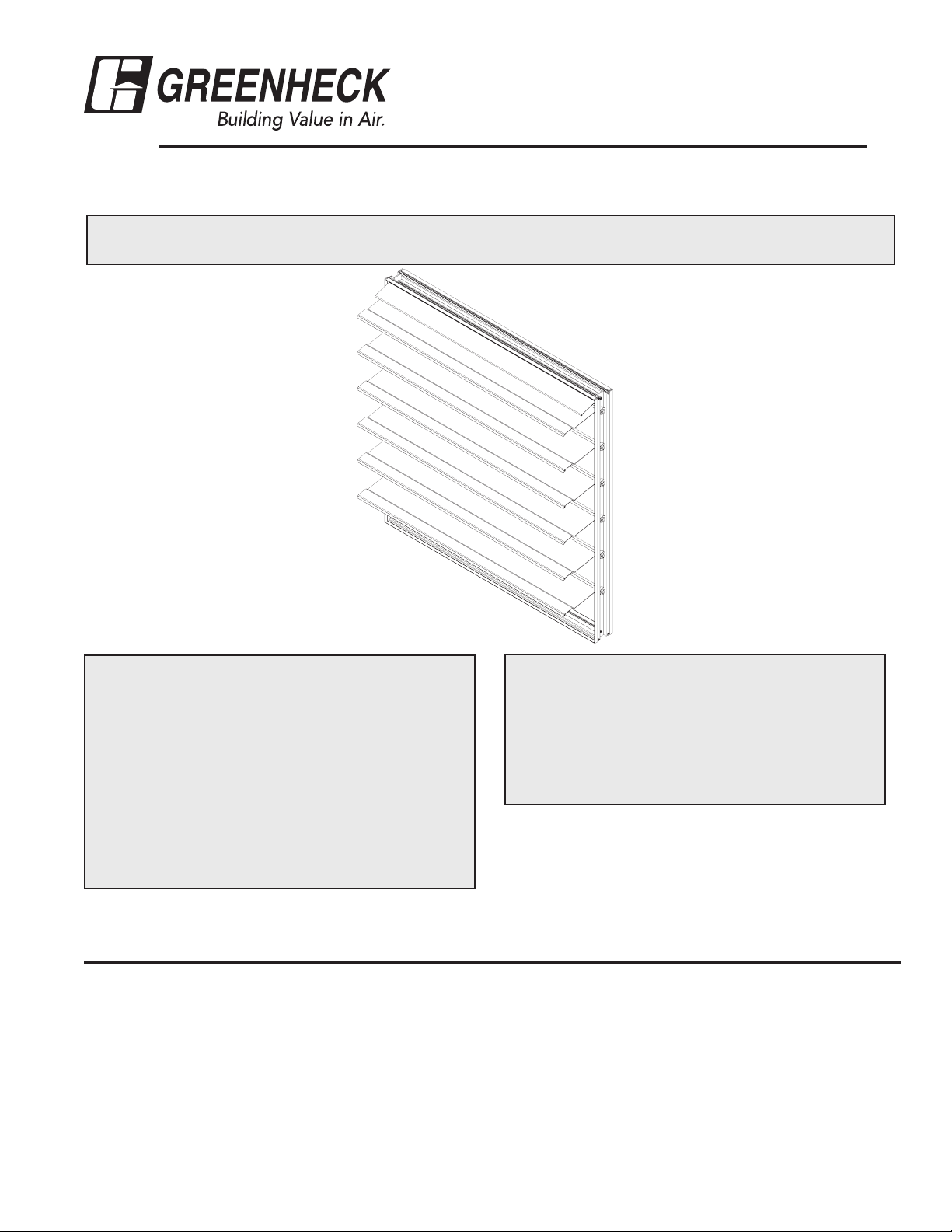
ES, EM & GM series
Installation, Operation, and Maintenance Instructions
This manual is the property of the owner, and is required for future maintenance. Please leave it with the
owner when the job is complete.
RECEIVING AND HANDLING
Upon receiving dampers, check for both obvious
and hidden damage. If damage is found, record all
necessary information on the bill of lading and file
a claim with the final carrier. Check to be sure that
all parts of the shipment, including accessories, are
accounted for.
Dampers must be kept dry and clean. Indoor
storage and protection from dirt, dust and the
weather is highly recommended. Do not store at
temperatures in excess of 100°F(37ºC).
Due to continuing research, Greenheck reserves the right to change specifications without notice.
Improper installation, adjustment, alteration,
service or maintenance can cause property
damage, injury or death. Read the installation,
operating, and maintenance instructions
thoroughly before installing or servicing this
equipment.
SAFETY WARNING:
Pre-Installation Guidelines
The basic intent of a proper installation is to secure the damper into the opening in such a manner as to prevent distortion
and disruption of damper operation. The following items will aid in completing the damper installation in a timely and
effective manner.
1) Check the schedules for proper damper locations within the building. Visually inspect the damper for damage.
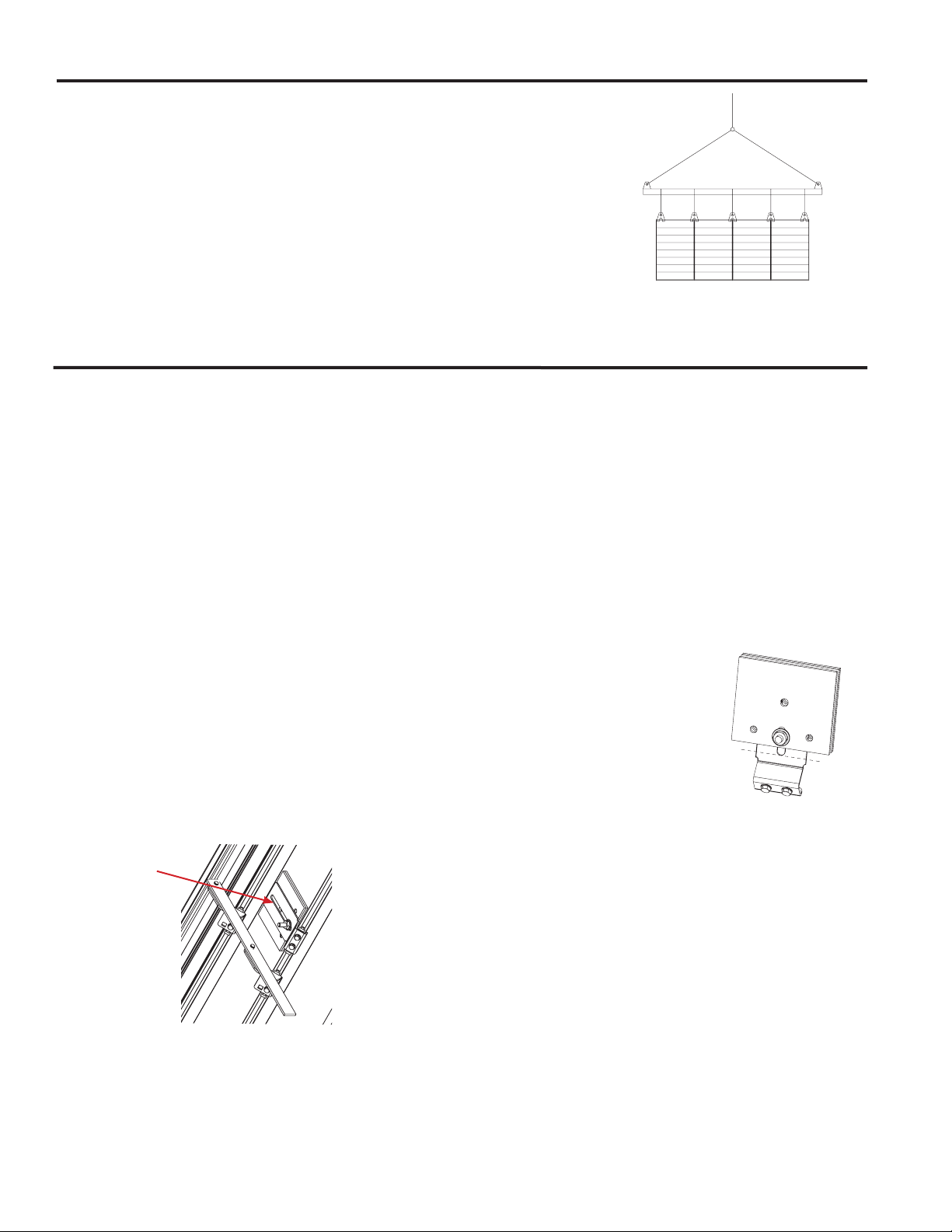
2) Lift or handle damper using sleeve or frame. Do not lift damper using blades or linkage. When handling multiple sections
assemblies, use sufficient support to evenly lift at each section mullion (see drawing). Do not drag, step on, apply
excessive bending, twisting, or racking. (See Figure 1)
3) Do not install screws in damper frame that will interfere with damper blades and prevent them from opening and/or
closing.
4) Damper must be installed into duct or opening square and free of twist or other misalignment. Damper must not be
squeezed or stretched into duct or opening. Out of square, racked, twisted or misaligned installations can cause
excessive leakage and/or torque requirements to exceed damper/actuator design.
Page 2
Pre-Installation Guidelines continued...
5) Damper must be kept clean, dry and protected from dirt, dust and other foreign
materials prior to and after installation. Examples of such foreign materials include
but are not limited to:
a) Drywall/mortar dust
b) Firesafing materials
c) Wall texture
d) Paint overspray
6) Damper should be sufficiently covered as to prevent overspray if wall texturing or
Spreader Bar
Attachments
spray painting will be performed within 5 feet (1.50m) of the damper. Excessive dirt
or foreign material deposits on damper can cause excessive leakage and/or torque
requirements to exceed damper/actuator design.
7) ACCESS: Suitable access (actuators maintenance, etc.) must be provided for damper
inspection and servicing. Where it is not possible to achieve sufficient size access, it
will be necessary to install a removable section of duct.
Multi section dampers
Figure 1
EM/ES/GM Damper Counterbalance Adjustment Procedure
The following instructions should be followed when attempting to maximize the counterbalance effect on the EM or
GM model dampers. Be aware that when the balance setting is highly sensitive, friction wear and contamination will
have an adverse effect to the operation of the damper. The sensitivity of the counterbalance should only be set to meet
the application requirements. The damper must be mounted square and plumb and operate freely before any weight
adjustments are performed.
Counterbalance adjustment for EM/ES/GM-30, 31 & 32 Models: Vertical Mount – Horizontal Airflow
Adjustment #1 will effect the balance of the blades in the open position. Adjustment #2 will effect the balance of the blades
in the closed position along with a small change to the open position balance.
If the damper blades do not achieve full open position under airflow and you want them to open further or all the way,
then adjustment #1 will need to be performed. If the damper blades do not open completely and adjustment #1 has been
addressed, then more weight is required.
If the airflow through the damper is light and the blades only slightly move from the closed position, then adjustment #2 and
#1 are required.
Adjustment #1:
Moving the weight stack along the length of the
mounting bracket slot will effect the full open balance
of the blade assembly. Moving the weights further
away from the blade pivot point will cause the blades
to become more balanced so that at some point, and
with enough weight, the blades would remain open.
Care must be taken to ensure that when the weights are
moved outward from the blade pivot point they will not
interfere with the adjacent blade when the blades close.
Moving the weights back towards the blade pivot point
will allow the blades to close.
blade surface. Bending the
counterweight mounting
brackets will move the
counterweight stack behind the
blade pivot point and therefore
allow the blades to start
opening at lower airflow rates.
This adjustment should be
performed in small increments
Bend Here
since the blades will not fully
close if the brackets are bent
to far. Performing adjustment #2
will have a small effect on adjustment #1 therefore, if
adjustment #1 is critical, then adjustment #1 may need
to be repeated.
Adjustment #2:
The damper is assembled with the counterbalance
weights and bracket installed such that, when the
blades are closed, the counterbalance weights and
bracket are positioned directly inline with the blade
pivot points. This position of the weights will provide
a slight load that will hold the blades in the closed
position. To reduce this load, the counterweightmounting brackets can be bent away from the adjacent
2
Counterbalance Adjustment for EM/ES-10, 11 &
12 Models: Horizontal Mount - Vertical Airflow Up
Adjustment #1 will effect the balance of the blades in the
closed position. Adjustment #2 will effect the balance of the
blades in the open position along with a small change to
the balance in the closed position balance.
If the damper blades are partially opening under airflow
and you want them to open further or all the way, then
adjustment #1 will need to be performed. If the blades
remain in the full open position then adjustment #2 is
required.
If the airflow through the damper is light and the blades
only slightly move from the closed position, then adjustment
#1 is required. If the airflow through the damper is light and
the blades do not reach full open position then adjustment
#2 may be excessive or adjustment #1 may need to be
Page 3

increased or both adjustments may need to be addressed.
Adjustment #1:
Moving the weight stack along the length of the
mounting bracket slot will effect the full closed balance
of the blade assembly. Moving the weights further
away from the blade pivot point will cause the blades
to become more balanced so that at some point, and
with enough weight, the blades would remain open
without air pressure being applied. Care must be taken
to ensure that when the weights are moved away from
the blade pivot point the weights will not interfere with
the adjacent blade when the blades close. Moving some
of the weights back towards the blade pivot point will
allow the blades to return to the closed position.
remain in the full open position then adjustment #2 is
required.
If the airflow through the damper is light and the blades
only slightly move from the closed position, then adjustment
#1 is required.
Adjustment #1:
Moving the weight stack along the length of the
mounting bracket slot will effect the full closed balance
of the blade assembly. Moving the weights closer to
the blade pivot point will cause the blades to become
less balanced so that at some point, the blades would
fall open. Care must be taken to ensure that when the
weights are moved outward from the blade pivot point
the weights will not interfere with the adjacent blade
when the blades close. Moving the weights away from
the blade pivot point will force the blades to close
properly. Care must be taken to ensure that when the
weights are moved outward from the blade pivot point
the weights will not interfere with the adjacent blade
when the blades close. Performing adjustment #1
will have a small effect on adjustment #2 therefore, if
adjustment #2 is critical, then adjustment #2 may need
to be repeated.
Adjustment #2:
The damper is factory assembled with the
counterbalance assembly installed such that, the
counterbalance weights and bracket are positioned at
a slight angle to the surface
of the blade. This angle will
position the weights such
that they will provide a slight
load that will cause the blades
to rotate from the full open
position toward the closed
position. If for some reason
the blades remain in the open
Bend Here
position then you will need to
increase this load. To do this
the counterweight-mounting
brackets should be bent further away from the blade
surface. Bending the counterweight mounting brackets
will move the counterweight stack away from the blade
surface and therefore the torsion effect will force the
blades to start closing. This adjustment should be
performed in small increments to each weight bracket.
Performing adjustment #2 will have a small effect on
adjustment #1 therefore, if adjustment #1 is critical,
then adjustment #1 may need to be repeated.
Counterbalance Adjustment for EM/ES-40, 41 &
42: Horizontal Mount – Vertical Airflow Down
Adjustment #1 will effect the balance of the blades in the
closed position. Adjustment #2 will effect the balance of the
blades in the open position along with a small change to
the balance in the closed position.
If the damper blades are only opening partially under airflow
and you want them to open further or all the way, then
adjustment #1 will need to be performed. If the damper
blades do not close completely and adjustment #1 has
been addressed, then more weight is required. If the blades
Adjustment #2:
The damper is factory assembled with the
counterbalance weights and bracket installed such
that, when the blades are closed, the counterbalance
weights and bracket are
positioned directly inline or
slightly ahead of the blade
pivot points. The position
of the weights will provide
a slight load that will cause
the blades to rotate from the
full open position toward the
closed position. To increase
this load, the counterweightmounting brackets can be
bent toward the adjacent blade surface. Bending
the counterweight mounting brackets will move the
counterweight stack which will force the blades to
start closing. This adjustment should be performed in
small increments to each weight bracket since bending
the brackets two much will cause the weight stack to
interfere with the adjacent blade surface. Performing
adjustment #2 will have a small effect on adjustment #1
therefore, if adjustment #1 is critical, then adjustment
#1 may need to be repeated.
Bend Here
3
Page 4

Multi-section Assembly
When the finished damper assembly is made up of multiple sections, the sections will require field assembly. Frame clips are
provided for this purpose. The frame clips are a snap fit component that fit over the joint between adjoining sections. The
clips will require the use of a rubber hammer or similar tool to install as shown below. Install frame clips on the front side and
backside of the assembly. For added strength, screws may be used on the backside of the frames in lieu of or in addition to
the frame clip. Do not install screws on the front side of the frame where they could interfere with the operation of the blades.
Note: Used only on EM series dampers.
Blade
Frame clip
Frame clip
Vertical joint shown. Horizontal joint is similar.
Front side of damper blade
overlaps the frame.
Use screws here if
necessary
Our Commitment
As a result of our commitment to continuous improvement, Greenheck reserves the right to change
specications without notice.
Specic Greenheck product warranties are located on greenheck.com within the product area tabs and in
the Library under Warranties.
®
Phone: (715) 359-6171 • Fax: (715) 355-2399 • E-mail: gfcinfo@greenheck.com • Website: www.greenheck.com
468391• EM & GM Series Rev. 4, April 2013 Copyright 2013 © Greenheck Fan Corporation
4
 Loading...