

Page 1
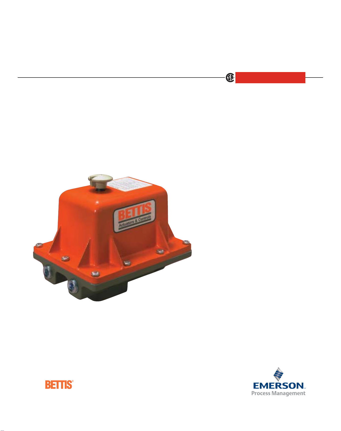
TorqPlus
Electric Valve
Actuators
and Controls
TM
Page 2
Introduction
Advantages
For more than 40 years, Bettis
Corporation has been recognized
worldwide for providing industry
with high performance pneumatic
and hydraulic valve actuators. The
addition of the Bettis line of TorqPlus
electric actuators carries on the
tradition of product quality, innovation and service reliability.
Bettis TorqPlus actuators are specifi-
cally designed for quarter-turn
operating applications — ball, butterfly and plug valves;
dampers; vents and similar uses. TorqPlus actuators are
available in a wide range of output torques and operating speeds to fit your specific requirements.
The Bettis Engineered Solution
Most electric actuators in use today are designed to
meet a range of torque and speed requirements for use
in industrial applications. Controls and optional accessories are often available, added at the factory while
being assembled. Heretofore, not much attention has
been given to field upgrades, inventory modifications or
parts replacement during servicing.
The Bettis TorqPlus actuators, instead, provide its users
with a unique modular approach. The actuators are
manufactured with pre-tapped holes in the base plate
to accommodate a myriad of control and accessory
components, available in more than 200 easy-to-install
kits to fit virtually every requirement imaginable. Kits
are available, depending on the actuator model, to add:
■ Heaters and thermostats
■ Potentiometers
■ Servo controls
■ Motor brakes
■ Positioners and transmitters
■ Control stations
■ Multi-turn operation
■ PLC interface
All of the components can be added inside the CSA type
4/4x weatherproof housing or the CSA type 4/4x, 7 and
9 weatherproof/explosion proof housings.
The Bettis TorqPlus, and the modular concept, offers its
users significant advantages:
■ Compact Design – The actuators provide maxi-
mum torque output relative to its small design
housing.
■ Custom Control Standards – By offering an
almost endless number of control and accessory
combinations, Bettis electric actuators can effectively be designed to virtually any end use.
■ Modular Construction – The modular design
allows the actuators to be easily field modified
and serviced. Accessory kits can be stored for
future use without consuming a large amount of
storage space.
■ High Strength Gearing – We precision-machine
our gears from hardened alloy steel, and run in
needle bearings. The result is efficiency, smooth
energy transfer, quiet operation and, best of all,
long service life.
■ Low Maintenance – Permanent lubrication
reduces the need for scheduled maintenance. The
actuators are supplied with low temperature
lubricant, allowing the units to perform in temperatures to -40°F (-40°C). All operational parts
are fully enclosed in the housing eliminating all
contact with the environment.
■ Guaranteed Minimum Torques – As with other
Bettis actuators, we guarantee that our published
output torque values are minimum values. If any
Bettis TorqPlus actuator fails to meet its specified
torque output under normal use, we will replace it.
■ Duty Cycle – All Bettis actuators are rated for a
duty cycle of at least 30% (one motor-on period
followed by two motor-off periods). Higher duty
cycles (up to 100%), which can allow for up to
1200 starts per hour, at normal ambient temperatures are available.
Page 3

The following information may be used as a guide to
compose specifications for Bettis TorqPlus Electric
Actuators. Bettis supplies Electric Actuators that meet
or exceed all of the specifications stated below except
the Model EM-100 (which is not equipped with a manual
override feature or dual conduit entrances).
1. General
The actuator shall consist of a sand cast CSA* Certified
enclosure complete with an internal high-torque
reversible electric motor, terminal block, heat-treated
alloy steel gearing, a minimum of two (2)1⁄ 2" NPT
conduit connections and a two (2) year original manufacturer’s warranty.
2. Actuator Sizing
All actuator torques must be published and must be guaranteed, by the original manufacturer, as minimum values.
The actuator shall be sized to produce a torque equal
to or greater than the maximum valve torque, including
safety factor, as stated by the valve manufacturer for
the service, operating conditions and ambient
temperature intended.
3. Ambient Temperature Range
The actuator shall be suitable for normal operation in
ambient temperatures ranging from -40 to +140 °F
(-40 to +60°C). For temperatures below 32°F (0°C), highhumidity environments or all outdoor applications the
actuator shall be supplied with an electric heater and
thermostat.
4. Electric Motors
The actuator motor shall be of the reversible, high-torque,
open frame ventilated design with built-in automatic
resetting thermal overload protection, a minimum 30%
duty cycle rating and be UL* and CSA* Certified Motors
of 1⁄4 hp or less with not more than 7 amps of locked
rotor current draw. When single phase motors are
selected, they shall be supplied as a permanent split
capacitor type operating from a 1Ph/60Hz/ 115VAC or
220VAC supply.
5. Reduction Gearing
The actuator shall use exclusively cut alloy gearing. All
power gearing shall be grease lubricated for long life.
6. Limit Switches
All limit switches shall be independently operated by
adjustable cams in each direction of operation. Provisions
shall be made for up to six (6) additional cam operated
switches, each being capable of operation at any point
of travel.
7. Torque Limit Switches
All actuators of 2,000 lb-in (226 Nm) output torque or
greater, shall be supplied with two (2) mechanical
torque limiting switches which shall be responsive to
maximum torque encountered in both directions of
travel.
8. Manual Override
Transfer to manual operation from motor operation
shall not require the use of hand levers, solenoid shifters
or handwheel depression and the transfer shall be positive and reliable.
Actuators of less than 1700 lb-in, except for the model
100, shall be supplied with a disengageable manual
override mechanism. Disengagement of the motor drive
shall permit the use of a wrench on the output shaft
flats and shall by-pass the power gear drive and motor
for manual operation.
Actuators of 2,000 lb-in (226 Nm) or greater output
torque shall be supplied with a handwheel which will
not rotate during motor operation, but must be operational at all times without danger of injury to operator.
The handwheel shall not require more than 50 lbs. of
rim force to operate under the most adverse conditions
and be capable of assisting or opposing the motor
without any form of declutching.
9. Enclosure
The actuator enclosure shall be a high-strength sand
casting and must be certified by CSA*, or equal third
party tester, as acceptable for use in the following
locations:
9.1 Non-hazardous indoor or outdoor location to protect against wind-blown dust and rain, splashing
water and hose-directed water (i.e. CSA Enclosure
4 – Weatherproof, conforms to IP-65).
9.2 Hazardous locations classified as Class I and II,
Groups C, D, E, F and G as defined in the National
Electrical Code plus non-hazardous locations to
protect against wind-blown dust and rain, splashing water and hose-directed water (i.e. CSA
Enclosure 4 and 7 – Explosion-proof and
Weatherproof).
*CSA is Canadian Standards Associations,
Rexdale Ontario, Canada M9W 1R3
*UL is Underwriters Laboratories, Inc.,
Northbrook, IL 60062
*NEMA is National Electrical Manufacturers Association,
Washington, D.C. 20037
TYPICAL SPECIFICATIONS
© 2002 Emerson. All rights reserved. 5M/01-02 Bulletin #81.20
Page 4
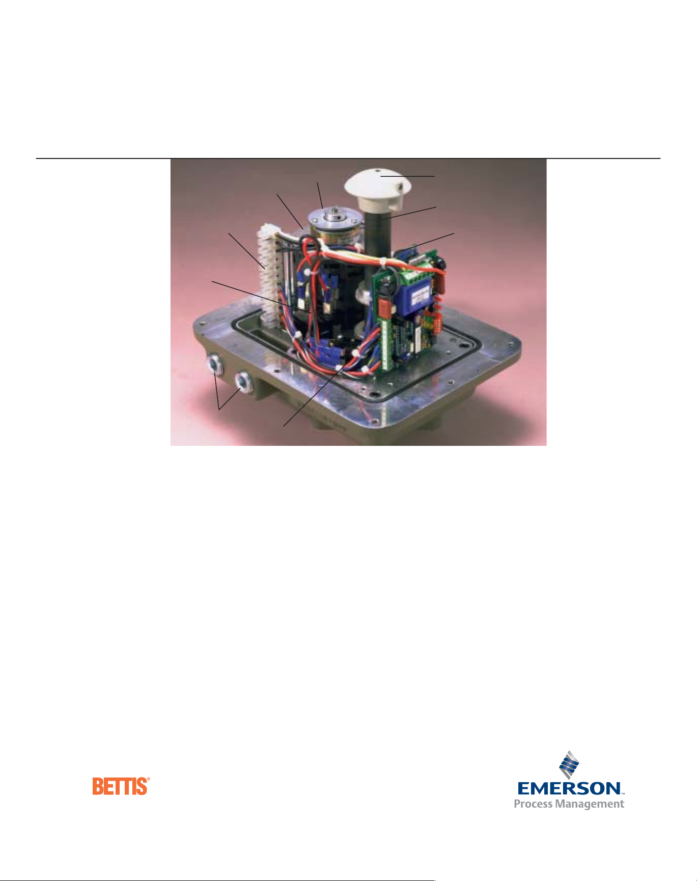
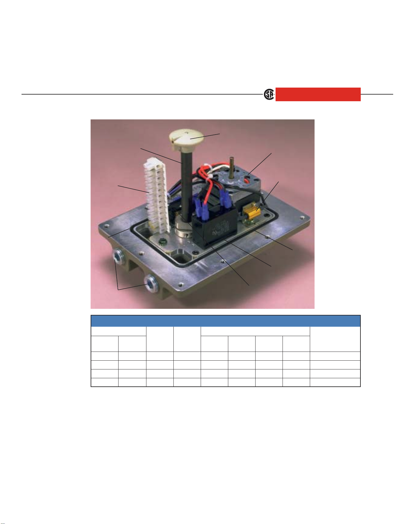
DESIGN AND CONSTRUCTION
2
1
4
5
8
9
These very rugged and versatile electric actuators take
full benefit of precision-machining which allows every
model to provide maximum torque output relative to its
compact design configuration and contains a minimum
of parts to reduce vibration, lessen noise and resist
harsh service. Utilizing a combination of spur, worm and
planetary power gearing reduction systems, the Bettis
TorqPlus actuators incorporate the most efficient, powerful and appropriate drive design for service excellence.
1. Motors. Available in Single Phase, 3 Phase and DC
voltages, all motors are custom built for high-torque,
low current draw and the highest duty cycle ratings
offered. Single phase motors are capacitor run type and
three phase are squirrel cage induction type both having
integral self resetting thermal cut-outs.
2. Brakes. Offered for all AC and DC motors, they are
capable of a holding force equal to the output torque
ratings of each actuator model.
3. Heater and Thermostat. Securely mounted and
appropriately sized to insure ample protection even in
the worst environments (not visible in photo).
4. Terminal Strips. Standard in all models and allow
7
10
6
(EM-500 Series)
easy plus efficient actuator installation.
5. Capacitors. Used on all single phase AC units, each
capacitor is peak voltage rated and of improved design
for maximum service life.
6. Potentiometers. Precision mechanically linked to
actuator output drive for continuous position signaling.
7. Position Indicator. Mechanically driven and easily
viewed at top of actuator to insure or confirm actual
actuator and driven device position at all times (not
available on compact Model EM-100).
8. Dual Conduit Connections. Standard on all models,
except EM-100, allows full electrical code access of all
wiring through two NPT connections.
9. Torque Limit Switches. Standard for the hightorque 800-Series of Bettis TorqPlus actuators. These
mechanical switches eliminate potential driven device
damage due to over torque conditions in either direction of operation.
10.Manual Override. Standard in all models except the
EM-100, manual override capability is offered in two
forms; Declutchable and Direct Acting.
Page 5
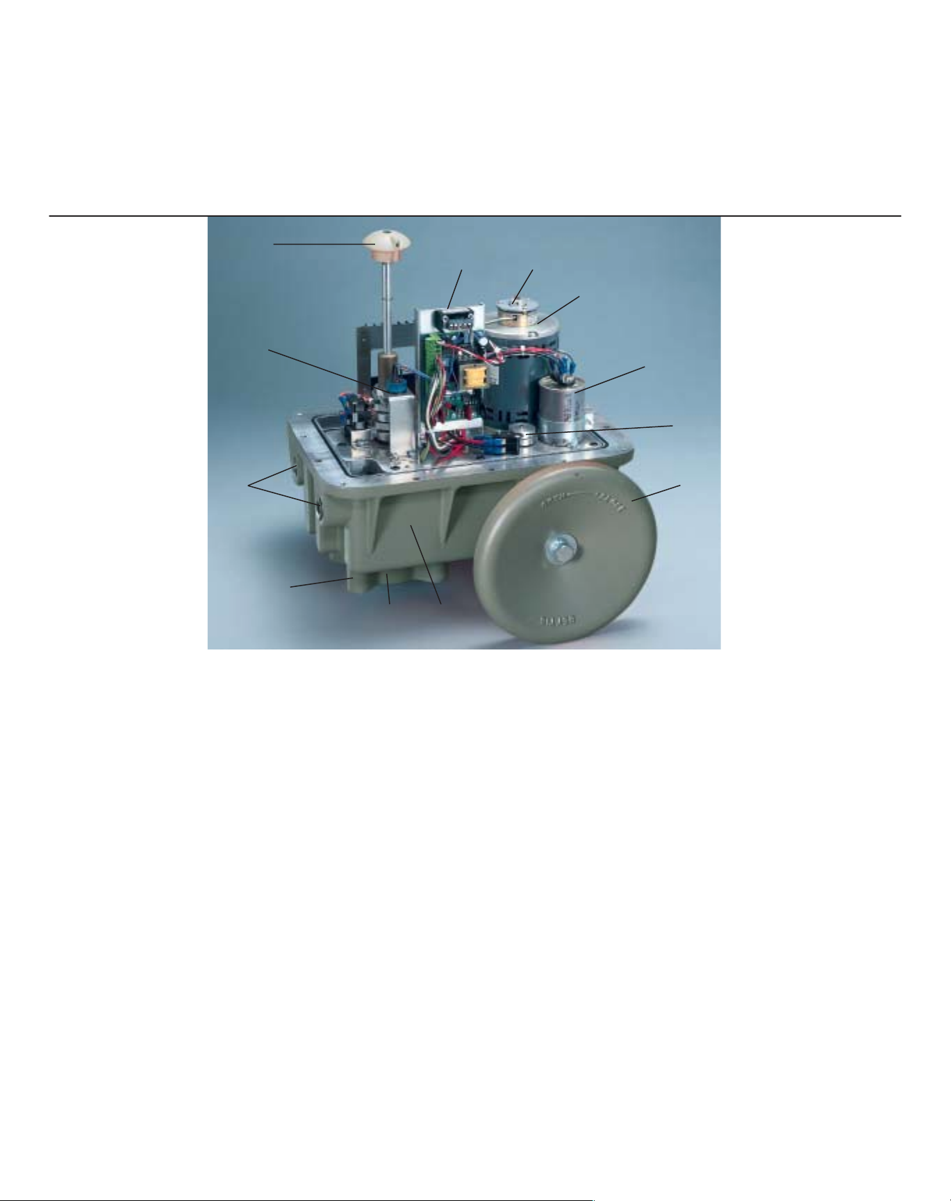
DESIGN AND CONSTRUCTION
7
6
4 2
1
5
9
8
11
12 13
(EM-800 Series)
Model EM-300 and the complete 500-Series
offer a Declutchable design which disengages the power
gear drive from the output shaft. Manual operation is
accomplished by rotating the exposed output shaft
drive flats with an open end wrench after the position
indicator knob is pulled up. Return to full automatic
operation is as easy as removing the wrench and lowering the position indicator knob to allow the mechanism
to re-engage upon application of power. Should power
be applied during manual operation, the declutchable
design will not allow the output shaft to rotate.
The 800-Series offers a Direct Acting handwheel design
which allows completely safe operation at any time and
with never more than 50 pounds of rim pull force.
Operating independent of the motor but directly into
the power gear drive, the handwheel does not rotate
during automatic operation of the actuator, requires no
engagement action for manual operation and may be
rotated with or without power to the unit.
10
11.Enclosures. Made from high strength sand castings,
enclosures are rated for applications in both Non-hazardous and Hazardous locations. As an option, the Bettis
TorqPlus is also available with a CSA Certified combination Hazardous and Non-hazardous enclosure for indoor
and outdoor protection in locations classified Class I and
II, Groups C, D, E, F and G as defined in the National
Electrical Code plus protects against wind-blown dust,
wind-blown rain, splashing water and hose-directed
water.
12.Output Drives are corrosion resistant. Female drives
are available in a variety of DIN/ISO 8-point sizes. Male
drives are also available on models 300 and 500. The
EM-800 series is provided with bored drive sleeve with
double keyways.
13.Powder Coat Finish. A polyester external coating
developed to serve as both a high durability impact and
chemical resistant finish. With up to 160 lb-in ASTM
D2794 impact resistance, over 1000 hours ASTM B117
salt spray rating and 1000+ hours ASTM D2247 humidity resistance, this protective finish will stay in place and
do the job.
© 2002 Emerson. All rights reserved. 5M/01-02 Bulletin #81.30
Page 6
TorqPlus Electric Actuators
TM
Torque 100 IN/LB
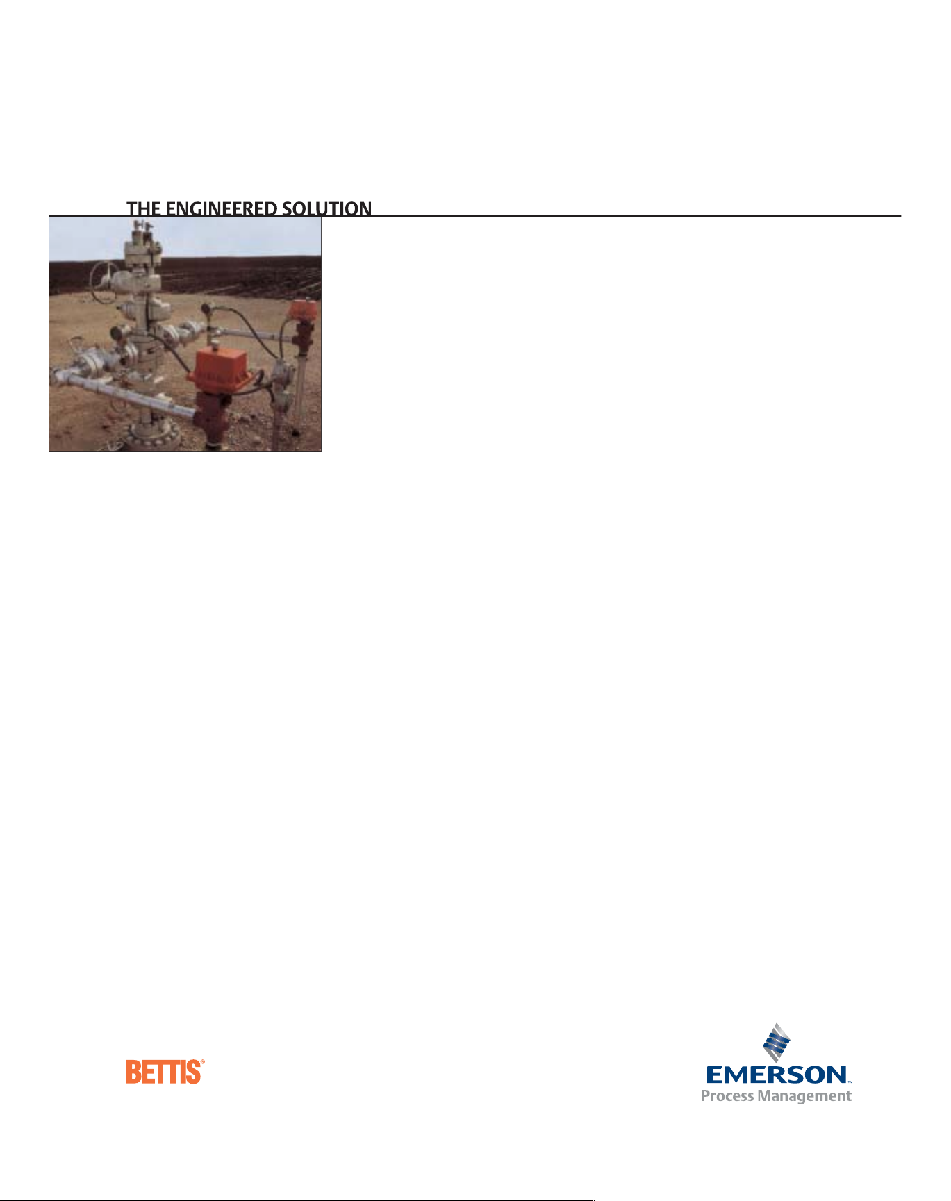
The Engineered Solution
MODEL EM-050
Bettis TorqPlus quality line of electric actuators are
designed for quarter turn applications — ball, butterfly
and plug valves; dampers; vents and similar uses.
TorqPlus actuators are manufactured in a wide range of
guaranteed output torques and operating speeds to fit
your specific requirements.
The Model EM-050 actuators offer compactness with a
rugged design to develop maximum torque in a small
package.
■ Single phase capacitor run motor with thermal
overload protection and internal motor brake
■ Enclosure designed to meet C.S.A.
specifications that conform to Nema type 1, 2, 3,
3R, 4, 4X, & 12
■ Two single pole double throw travel-stop limit
switches with adjustable cams
■ Female DIN/ISO F03 output drive sleeve and
DIN/ISO F03 bolt pattern
■ Operational in any mounting orientation
■ Weight: 5.7 lbs
■ Single 1/2-inch NPT conduit entrance
OPTIONAL FEATURES
■ Maximum of two additional single pole double
throw auxiliary limit switches
■ Heater and thermostat
■ Canadian Standards Association general purpose
for electrical certification available under file
#LR90062
STANDARD FEATURES
■ Two year warranty
■ Permanently lubricated gear train
■ Stainless steel output drive sleeve
■ Operating temperatures:
-40°F with heater activated, to +140° F
Page 7
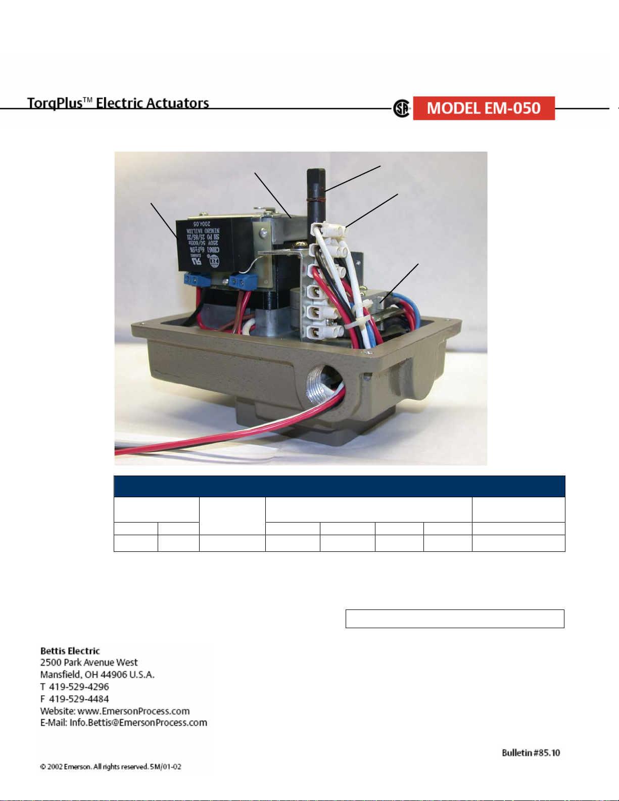
Torque 100 IN/LBS
Capacitor
Motor
Output Drive
Shaft
Terminal Strip
Female DIN-ISO Mounting
MODEL EM-050 SERIES
TORQUE LOCKED ROTOR AMP
IN/LB NM
100 11 2 1/2 SEC 0.51 N/A N/A N/A 50% N/A
SPEED
90º
115VAC 220VAC 12VDC 24VDC AC DC
Full Load Amps Per CSA Tag on Actuator 0.45
MOTOR DUTY
CYCLE @ 75 º F
Page 8
TorqPlusTMElectric Actuators
Torque 100 IN/LB – 350 IN/LB
The Engineered Solution
MODEL EM-100
Bettis TorqPlus quality line of electric actuators are
designed for quarter turn applications — ball, butterfly
and plug valves; dampers; vents and similar uses.
TorqPlus actuators are manufactured in a wide range of
guaranteed output torques and operating speeds to fit
your specific requirements.
The Model EM-100 actuators offer compactness with a
rugged design to develop maximum torque in a small
package.
■ Single phase capacitor run motor with thermal
overload protection and internal motor brake for
250 in/lb and 350 in/lb models
■ Enclosure certified to weatherproof C.S.A.
specifications that conform to Nema type 1, 2, 3,
3R, 4, 4X, & 12
■ Two single pole double throw travel-stop limit
switches with adjustable cams
■ Female DIN/ISO output drive sleeve and DIN/ISO
bolt pattern
■ Operational in any mounting orientation
■ Weight: 5 lbs
■ Single 1/2-inch NPT conduit entrance
OPTIONAL FEATURES
■ Maximum of two additional single pole double
throw auxiliary limit switches
■ Heater and thermostat
■ Canadian Standards Association general purpose
for electrical certification available under file
#LR90062
■ Standard 1KΩ potentiometer. Other ranges
provided upon request.
■ Relay control
■ Electronic proportional positioner for 4-20 mA,
1-5 VDC, or 0-10 VDC control input and 4-20mA
output signal
■ Optional voltages
230 VAC 50/60 Hz single phase
12/24 VDC
24 VAC
STANDARD FEATURES
■ Two year warranty
■ Permanently lubricated gear train
■ Stainless steel output drive sleeve
■ Operating temperatures:
-40°F with heater activated, to +140° F
■ Unidirectional motor with thermal overload pro-
tection and mechanical brake for 100 in/lb model
Page 9
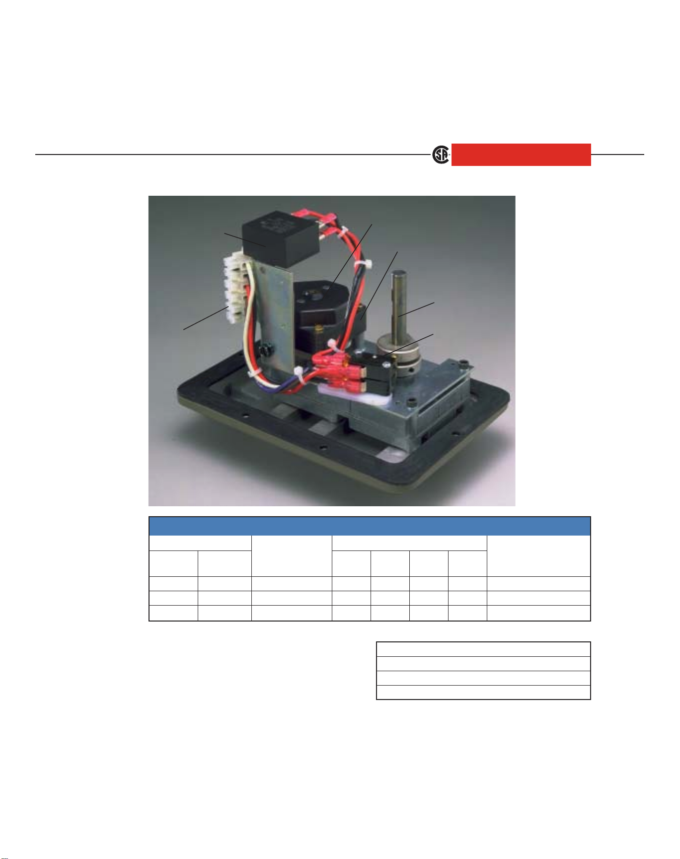
TorqPlusTMElectric Actuators
Torque 100 IN/LB – 350 IN/LB
Capacitor
MODEL EM-100
Brake
Motor
Output Drive
Shaft
Terminal
Limit Switch
Strip
Female DIN-ISO Mounting
MODEL EM-100 SERIES
TORQU E
IN/lB NM 90° 115VAC 220VAC 12VDC 24VDC
100 11 2 SEC 1.30 CF* N/A N/A 30% N/A
250 28 10 SEC 0.70 CF* .70 1.40 30% 100%
350 39 13 SEC 0.70 CF* N/A N/A 30% N/A
* Consult factory for 230VAC locked rotor current.
SPEED
LOCKED ROTOR AMP
MOTOR DUTY
CYCLE @ 75°F
AC DC
Model # Mounting Bolt Circle Drive Sleeve
133 F03 F03
144 F04 F04
Bettis Electric
2500 Park Avenue West
Mansfield, OH 44906 U.S.A.
T 419-529-4296
F 419-529-4484
Website: www.EmersonProcess.com/Bettis
E-Mail: Info.Bettis.Electric@EmersonProcess.com
© 2002 Emerson. All rights reserved. 5M/01-02 Bulletin #85.10
155 F05 F05
Page 10
TorqPlusTMElectric Actuators
Torque 150 IN/LB – 600 IN/LB
The Engineered Solution
MODEL EM-300
Bettis TorqPlus quality line of electric actuators are
designed for quarter turn applications — ball, butterfly
and plug valves; dampers; vents and similar uses.
TorqPlus actuators are manufactured in a wide range of
guaranteed output torques and operating speeds to fit
your specific requirements.
The Model EM-300 actuators combine compactness
with manual override capability and an extensive array
of available options for a broad spectrum of applications.
STANDARD FEATURES
■ Two year warranty
■ Heater and thermostat installed in all actuators
■ Case hardened steel spur gear train is permanently
lubricated
■ Hardened steel drive shaft
■ Female DIN/ISO F04 output drive and bolt pattern
or male output drive
■ Operating temperatures:
-40° F with standard heater activated to +140° F
■ Single phase capacitor run motor with thermal
overload protection
■ Internal motor brake on 4 and 10 second units
■ Enclosure certified to weatherproof C.S.A. specifi-
cations that conform to NEMA type 1, 2, 3,
3R, 4, 4X & 12
■ Two single pole double throw travel-stop limit
switches with adjustable cams
■ Declutchable manual override with position
indicator
■ Dual 1/2-inch NPT conduit entrance
■ Operational in any mounting orientation.
■ Weight: 11 to 12 lbs
OPTIONAL FEATURES
■ 75% or 100% extended duty cycle motors
■ Electromechanical brake for 15 second and 30
second units
■ Standard 1KΩ potentiometer. Other ranges pro-
vided upon request.
■ Relay control
■ Electronic proportional positioner for 4-20 mA,
1-5 VDC, or 0-10 VDC control input and 4-20mA
output signal
■ Optional voltages
230 VAC 50/60 Hz single phase
12/24 VDC
24 VAC
■ Maximum of four additional auxiliary single
pole double throw auxiliary limit switches with
adjustable cams.
■ Handwheel
■ Canadian Standards Association general purpose
for electrical certification available under file
#LR90062
■ Dual purpose weatherproof and explosion-proof
enclosures are certified by Canadian Standards
Association for services: Class I Groups C,D,
Division I; Class II Groups E,F,G Division I that
conform to NEMA type 7 and 9
Page 11
TorqPlusTMElectric Actuators
Torque 150 IN/LB – 600 IN/LB
Output
Drive shaft
MODEL EM-300
Position Indicator
Motor and Brake
Terminal
Strip
Heater
O-Ring Seal
Capacitor
Tra vel -St op
Dual Conduit
Limit Switches
Connection
MODEL EM-300 SERIES
TORQU E
IN/IB NM 90° 115VAC 230VAC 12VDC 24VDC
150 17 4 SEC 300-04 0.57* 0.29 1.2A 2.5A **30% 100%
300 34 10 SEC 300-10 0.57* 0.29 1.2A 2.5A **30% 100%
400 45 15 SEC 300-15 0.56* 0.25 1.2A 2.5A **30% 100%
600 68 30 SEC 300-30 0.56* 0.25 1.2A 2.5A **30% 100%
* Locked rotor current for all 75% and 100% duty cycle motors is 0.50 amp
SPEED MODEL
LOCKED ROTOR AMP MOTOR DUTY
CYCLE @ 75°F
AC DC
**75% and 100% duty cycle motors are available for 115 VAC service
Bettis Electric
2500 Park Avenue West
Mansfield, OH 44906 U.S.A.
T 419-529-4296
F 419-529-4484
Website: www.EmersonProcess.com/Bettis
E-Mail: Info.Bettis.Electric@EmersonProcess.com
© 2002 Emerson. All rights reserved. 5M/01-02 Bulletin #82.10
Page 12

TorqPlusTMElectric Actuators
Torque 350 IN/LB – 1600 IN/LB
The Engineered Solution
MODEL EM-500
Bettis TorqPlus quality line of electric actuators are
designed for quarter turn applications — ball, butterfly
and plug valves; dampers; vents and similar uses.
TorqPlus actuators are manufactured in a wide range
of guaranteed output torques and operating speeds to
fit your specific requirements.
The Model EM-500 Series are designed for the entire
mid-range of torques and operating speeds, with a
rugged versatility that is hard to beat.
STANDARD FEATURES
■ Two year warranty
■ Heater and thermostat installed in all actuators
■ Hardened steel spur gear train is permanently
lubricated
■ Hardened steel drive shaft
■ Female DIN/ISO F07 output drive and F07/F10
bolt pattern or male output drive
■ Operating temperatures:
-40° F with standard heater activated, to +140° F
■ Single phase capacitor run motor with thermal
overload protection
■ Enclosure certified to weatherproof C.S.A.
specifications that conform to NEMA type 1, 2, 3,
3R, 4, 4X and 12
■ Declutchable manual override with position
indicator
■ Dual 1/2-inch NPT machined conduit entrances
■ Captive hex bolts on enclosure
■ Operational in any mounting orientation
■ Two single pole double throw end of travel stop
limit switches with adjustable cams
■ Weight: 17 to 18 lbs
OPTIONAL FEATURES
■ Electromechanical brake
■ Standard 1KΩ potentiometer, other ranges pro-
vided upon request
■ Electronic proportional positioner for 4-20mA, 1-
5 VDC, or 0-10 VDC control input, and
4-20mA output signal
■ Relay control
■ Optional voltages
220 VAC 50/60 Hz single phase
12/24 VDC
24 VAC
■ Maximum of four additional single pole double
throw auxiliary limit switches with adjustable cams
■ Handwheel
■ Dual purpose weatherproof and explosion-proof
enclosures are certified by Canadian Standards
Association for services: Class I Groups C,D,
Division I; Class II Groups E,F,G Division I that
conform to NEMA type 7 and 9
■ Canadian Standards Association general purpose
for electrical certification available under file
#LR90062
Page 13

TorqPlusTMElectric Actuators
Torque 350 IN/LB – 1600 IN/LB
MODEL EM-500
Motor
Terminal
Strips
Capacitor
Dual Conduit
Connections
Brake
Tra vel -St op
Limit Switch
Position Indicator
Output
Drive Shaft
Potentionmeter
Electronic
Proportional
Positioner
O-Ring Seal
*Heater and Thermostat not shown.
MODEL EM-500 SERIES
TORQU E
IN/IB NM 90° 115VAC 230VAC 12VDC 24VDC
350 39 5 SEC 500-05 0.69 0.36 4.3 5.0 100% 100%
700 79 10 SEC 500-10 0.69 0.36 4.3 5.0 100% 100%
1000 113 15 SEC 500-15 0.69 0.36 4.3 5.0 100% 100%
1600 181 30 SEC 500-30 0.35 0.45 4.3 5.0 100% 100%
325 36 2 SEC 510-02 1.57 0.80 4.3 8.5 100% 100%
600 68 5 SEC 510-05 1.57 0.80 4.3 8.5 100% 100%
1000 113 7 SEC 510-07 1.57 0.80 4.3 8.5 100% 100%
180 20 5 SEC 520-05 0.57 0.29 1.2 2.5 30% 100%
450 51 10 SEC 520-10 0.57 0.29 1.2 2.5 30% 100%
600 68 15 SEC 520-15 0.57 0.29 1.2 2.5 30% 100%
1000 113 30 SEC 520-30 0.57 0.29 1.2 2.5 30% 100%
Bettis Electric Mansfield, OH U.S.A. T 419-529-4296 Website: www.EmersonProcess.com/Bettis
© 2002 Emerson. All rights reserved. 5M/01-02 Bulletin #86.10
SPEED MODEL
LOCKED ROTOR AMP MOTOR DUTY
CYCLE @ 75°F
AC DC
Page 14

TorqPlusTMElectric Actuators
Torque 2,000 IN/LB – 20,000 IN/LB
The Engineered Solution
MODEL EM-800
Bettis TorqPlus quality line of electric actuators are
designed for quarter turn applications — ball, butterfly
and plug valves; dampers; vents and similar uses.
TorqPlus actuators are manufactured in a wide range of
guaranteed output torques and operating speeds to fit
your specific requirements.
The EM-800 Series utilizes a highly effective planetary
gearing system and a handwheel manual override to
produce maximum torques in a compact package.
STANDARD FEATURES
■ Two year warranty
■ Heater and thermostat installed in all actuators
■ Case hardened steel spur gear train is permanent-
ly lubricated
■ Operating temperatures:
-40° F with standard heater activated, to +140° F
■ Single phase capacitor run motor with thermal
overload protection
■ Enclosure certified to weatherproof C.S.A.
specifications that conform to NEMA type 1, 2,
3,3R, 4 and 12
■ Handwheel manual operation
■ Mechanical position indicator
■ Captive hex bolts on enclosure
■ Dual 3/4-inch NPT machined conduit entrances
■ Two single pole double throw travel-stop limit
switches with adjustable cams and 2 aux S.P.D.T.
■ Female drive
■ Weight: 65-70 lbs (type 4), 150-160 lbs
(explosion-proof)
■ Two mechanical torque limit switches
OPTIONAL FEATURES
■ Dual purpose weatherproof and explosion-proof
enclosures are certified by Canadian Standards
Association for services: Class I Groups C,D,
Division I; Class II Groups E,F,G Division I that
conform to NEMA type 7 and 9
■ Standard 1K potentiometer, other ranges provid-
ed upon request
■ Electronic proportional positioner for 4-20 mA,
1-5 vDC, or 0-10 vDC control input and 4-20mA
output signal
■ Optional voltages
220 VAC 50/60 Hz single phase
220 VAC 50/60 Hz 3 phase
■ Relay control
■ Maximum of four additional single pole double
throw auxiliary limit switches with adjustable cams
■ Electromechanical brake
■ Canadian Standards Association general purpose
for electrical certification available under file
#LR90062
Page 15

TorqPlusTMElectric Actuators
Torque 2,000 IN/LB – 20,000 IN/LB
MODEL EM-800
Position Indicator
Terminal Strips
Tra vel -St op
Limit
Switches
Dual Conduit
Connections
Planetary
Gearing System
BrakeHeater
Motor
Capacitor
To rqu e
Limit Switches
O-Ring Seal
Direct
Acting
Manual
Override
Electronic
Proportional
Positioner
MODEL EM-800 SERIES
TORQUE SPEED MODEL LOCKED ROTOR AMP MOTOR DUTY
IN/IB NM 90° 115VAC 230VAC CYCLE @ 75°F
2000 226 12 SEC 810-12 3.15 1.3 100%
2500 282 18 SEC 810-18 3.15 1.3 100%
3500 395 30 SEC 810-30 3.15 1.3 100%
4000 452 60 SEC 810-60 3.15 1.3 100%
3000 338 12 SEC 820-12 3.15 1.3 100%
4000 452 18 SEC 820-18 3.15 1.3 100%
6000 678 30 SEC 820-30 3.15 1.3 100%
7000 791 60 SEC 820-60 3.15 1.3 100%
5000 565 12 SEC 830-12 5.97 2.81 100%
7000 791 18 SEC 830-18 5.97 2.81 100%
10000 1130 30 SEC 830-30 5.97 2.81 100%
10000 1130 60 SEC 830-60 5.97 2.81 100%
15000 1695 48 SEC 840-48 5.97 2.81 100%
20000 2260 72 SEC 840-72 5.97 2.81 100%
Bettis Electric Mansfield, OH U.S.A. T 419-529-4296 Website: www.EmersonProcess.com/Bettis
© 2002 Emerson. All rights reserved. 5M/01-02 Bulletin #84.10
Page 16

TorqPlusTMElectric Actuators
Torque 300 IN/LB – 1,600 IN/LB
MODEL EM-SR5
The Engineered Solution
Bettis TorqPlus has taken the lead in offering compact,
cost effective Spring Return Electric Actuator Packages.
Three models offer a variety of solutions when one needs
to protect a system upon loss of power. These actuators
have been designed for dampers, small
butterfly, ball and plug valves.
The Model EM-SR5 Series
is designed for use in
environments where auto-
matic closing/opening
is required upon loss of
power, with a rugged
versatility that is hard
to beat.
When power is
available, the
device operates like
a normal quarter turn,
open/close or modulating
actuator. Under powered operation, the spring pack travels with
the movement of the actuator.
Under powered stopped
conditions, the actuator and
spring are held in position
via the electric mechanical
brake. Upon loss of power, the
spring is released and drives
actuator to the predesignated
failsafe position. The failsafe
positioning can be provided for
either the CCW limit or to the
CW limit.
the
STANDARD FEATURES
■ Two year warranty
■ Heater and thermostat
■ Case hardened steel spur gear train is
permanently lubricated
■ Operating temperatures:
-40° F, with standard heater activated, to +140° F
■
Thermally protected permanent split capacitor motor
■ Electromechanical brake
■ CW or CCW spring return
■ Dual 1/2-inch NPT conduit entrances
■ Captive hex bolts on enclosure
■ Operational in any mounting orientation
■
Limit switches with independent end of travel cams
■ Male output drive on all models or female
DIN/ISO F04 or F05 output drive on 10, 15 and 30
second models
■
Adjustable mechanical stop at the fail safe position
■ Visual position indicator
■ Enclosure certified to weatherproof C.S.A. specifi-
cations that conform to NEMA type 1, 2, 3, 3R, 4,
4X and 12
OPTIONAL FEATURES
■ Modulating service (separate enclosure)
■ Standard 1KΩ potentiometer, other ranges
provided upon request
■ Optional 220 VAC 50/60 Hz motor
■ Up to four auxiliary switches with adjustable cams
■
Canadian Standard Association general purpose for
electrical certification available under file #LR90062
■ Dual purpose weatherproof and explosion-proof
enclosures are certified by Canadian Standards
Association for services: Class I Groups C,D,
Division I; Class II Groups E,F,G Division I that
conform to NEMA type 7 and 9
MODEL EM-SR5 SERIES
To rq ue To rq ue
(against spring) (with spring) Speed (sec/90°) Motor Ratings
Model in/lb nm in/lb nm Motor Spring LRA FLA
Duty Cycle
SR5-10 300 34 350 40 10 4 0.69 0.34 100% 28-30
SR5-15 400 45 450 51 15 5 0.69 0.34 100% 28-30
SR5-30 600 68 700 79 30 6 0.35 0.30 100% 36-38
SR5-90 1600 181 1400 158 90 25 0.35 0.30 100% 138
Weight
(lbs)
Page 17

TorqPlusTMElectric Actuators
Torque 300 IN/LB – 1,400 IN/LB
MODEL EM-SR5
Brake
Motor
Terminal
Strip
Capacitor
Dual Conduit
Connections
DIN-ISO Mounting/
Female Drive
Position Indicator
Output
Drive Shaft
Heater &
Thermostat
O-Ring Seal
Limit Switch
Adjustable
Spring Stop
EM-SR5-90 with
Gear Reduction Box
Bettis Electric Mansfield, OH U.S.A. T 419-529-4296 Website: www.EmersonProcess.com/Bettis
© 2002 Emerson. All rights reserved. 5M/01-02 Bulletin #88.10
Page 18

Assembly Layout Drawings
7 1/2
TALL COVER
MODEL EM-050
5.00 CLEARANCE
FOR COVER REMOVAL
6 3/4
1.002
5 1/2
2 3/16
501
F03 MOUNTING WITH
F03 DRIVE SLEEVE
.359
X .44 DEEP (TYP.)
.354
.561
X .63 DEEP (TYP.)
.556
SHORT COVER
#10-24 TAP - .35 DEEP
(4) HOLES ON 1.42 DIA. BOLT CIRCLE
ACROSS CORNERS MIN.
.476
2 1/4
5 1/4
1.169
.585
#10-24 TAP - .35 DEEP
(4) HOLES ON 1.65 DIA. BOLT CIRCLE
7/8
1 5/8
.443
X .51 DEEP (TYP.)
.438
.554
ACROSS CORNERS MIN.
F04 MOUNTING WITH
F04 DRIVE SLEEVE
#8-32 PHIL.
PAN HEAD
(6) PLACES
1/2-14 NPT
CONDU T ENTRY
I
SUPPLIED WITH
PLUG
1.392
.696
F05 MOUNTING WITH
F05 DRIVE SLEEVE
1/4-20 TAP - .35 DEEP
(4) HOLES ON 1.97 DIA. BOLT CIRCLE
.713
ACROSS CORNERS MIN.
Page 19

Assembly Layout Drawings
7 1/2
TALL COVER
MODEL EM-100
5.00 CLEARANCE
FOR COVER REMOVAL
6 3/4
1.002
5 1/2
2 3/16
501
F03 MOUNTING WITH
F03 DRIVE SLEEVE
.359
X .44 DEEP (TYP.)
.354
.561
X .63 DEEP (TYP.)
.556
SHORT COVER
#10-24 TAP - .35 DEEP
(4) HOLES ON 1.42 DIA. BOLT CIRCLE
ACROSS CORNERS MIN.
.476
2 1/4
5 1/4
1.169
.585
#10-24 TAP - .35 DEEP
(4) HOLES ON 1.65 DIA. BOLT CIRCLE
7/8
1 5/8
.443
X .51 DEEP (TYP.)
.438
.554
ACROSS CORNERS MIN.
F04 MOUNTING WITH
F04 DRIVE SLEEVE
#8-32 PHIL.
PAN HEAD
(6) PLACES
1/2-14 NPT
CONDUIT ENTRY
SUPPLIED WITH
PLUG
1.392
.696
F05 MOUNTING WITH
F05 DRIVE SLEEVE
1/4-20 TAP - .35 DEEP
(4) HOLES ON 1.97 DIA. BOLT CIRCLE
.713
ACROSS CORNERS MIN.
Page 20

TorqPlusTMElectric Actuators
MODEL EM-300
EM-310
EM-320
8 1/4
5" MIN. CLEARANCE FOR
COVER REMOVAL
1/2-14 NPT
CONDUIT ENTRY
WITH (2) PIPE
PLUGS SUPPLIED
7 1/2
6 13/32
1 1/2
3
1 1/4
3 1/8
6 1/4
OPEN/CLOSE INDICATOR
.461 ACROSS FLATS
1/2
.44
OPTIONAL MALE OUTPUT
1.168
DIN/ISO F04 FLANGE
F04 DIN/ISO FEMALE DRIVE
TYP.
.584
TYP.
10-24 TAP X 1/2 DEEP
(4) HOLES ON 1.65 DIA. BOLT CIRCLE
45°
.437
SQ. X .50 DEEP (TYP.)
.433
.585 ACROSS CORNERS MIN.
1.500
.750
SQ.
FLANGE DIMENSIONS
WITH MALE OUTPUT
.281
.279
10-24 TAP - .50 DEEP
(4) HOLES
45°
CENTERED
FLATS
DIA.
.456
Bettis Electric
2500 Park Avenue West, Mansfield, OH 44906 U.S.A. T 419-529-4296 F 419-529-4484
Website: www.EmersonProcess.com/Bettis E-Mail: Info.Bettis.Electric@EmersonProcess.com
© 2002 Emerson. All rights reserved. 5M/01-02 Bulletin #85.15
Page 21

Assembly Layout Drawings
1/2-14 NPT
CONDU IT
ITH
ENTRY W
(2) PIPE
PLUGS
SUPPLIED
2 7/16
1 5/8
6" MIN. CLEARANCE FOR
COVER REMOVAL
1/4-20 S.S. CAPTIVE HEX
SLOTTED SCREW (8 TOTAL)
8
9 7/16
MODEL EM-500
EM-510
EM-520
OPEN/CLOSE
INDICATOR
1 5/8 2 1/2 3 3/4
9 3/4
F07/F10 DIN/ISO FLANGE
F07 DIN/ISO FEMALE DRIVE
5/16-18 TAP .50 DEEP
(4) HOLES EQ. SPACED
ON A 2.76 DIA. B.C.
(F07 FLANGE MOUNTING
PER DIN/ISO)
2.839 TYP
1.419 TYP
3/8-16 TAP - .60 DEEP
(4) HOLES EQ. SPACED
ON A 4.02 DIA. B.C.
(F10 FLANGE MOUNTING PER DIN/ISO)
1.943
.969
.90
OPTIONAL
MALE OUTPUT
45
°
TYP
.669
SQ. TYP.
.673
.75 DEEP
.920
ACROSS CORNERS
MIN.
5/16-18 TAP - .50 DEEP
(4) HOLES
2.250 TYP
1.125 TYP
#10-24 TAP - .50 DEEP
(4) HOLES
.626
.624
7 3/4
FLANGE DIMENSIONS
WITH MALE OUTPUTS
3 7/8
.750 TYP
1.500 TYP
1.03
.875 DIA
Page 22

TorqPlusTMElectric Actuators
13 5/16
15 3/8
MODEL EM-810
EM-820
EM-830
8" CLEARANCE FOR
COVER REMOVAL
14
2 11/16
4 1/2
3/4-14 NPT
STANDARD
CONDUIT ENTRY
3/8-16 TAP X 3/4 DEEP
4-HOLES AS SHOWN
ON 3.250 DIA. B.C.
1.385/1.378 DIA.
X 1-3/4 DEEP
2 3/4
5 1/2
.254
X 1-1/2 DEEP
.250
2-PLACES
1/2-13 TAP X 7/8 DEEP
4-HOLES AS SHOWN
ON 5.000 DIA. B.C.
1.503
1.498
2-PLACES
Bettis Electric
2500 Park Avenue West, Mansfield, OH 44906 U.S.A. T 419-529-4296 F 419-529-4484
Website: www.EmersonProcess.com/Bettis E-Mail: Info.Bettis.Electric@EmersonProcess.com
3 7/8
9 11/16
14
© 2002 Emerson. All rights reserved. 5M/01-02 Bulletin #84.15
Page 23

Assembly Layout Drawings
13 5/16
7 5/8
BEVEL GEAR ACTUATOR
MODEL EM-840
3/4 NPT CONDUIT
ENTRANCES
DYNATORQ UE
BG4
31 3/8
25 7/8
POSITION
INDICATOR
7 1/2
1/2-13 TAPPED 3/4 DEEP
8 HOLES ON 7.625 DIA. B.C.
14
SHAFT NOTE: STANDARD OR MACHINED
TO CUSTOMER REQUIREMENTS.
Page 24

TorqPlusTMElectric Actuators
MODEL EM-SR5-10
EM-SR5-15
15 3/8
8 3/8
4 1/8 3 3/4
1 5/8
1 5/8
2.75 DIA.
1.170
.585
9 3/4
SEE NOTE 1
1/2 NPT
CONDUIT
ENTRANCES
SPRING RETURN
PACK
F04 OUTPUT ADAPTER
F04 FEMALE OUTPUT
DRIVE
1/4-20 X .50 TAP
(4) HOLES ON 1.650 DIA. BOLT CIRCLE
13 13/16
.79
7 3/4
POSITION
INDICATOR
CLOCKWISE SPRING
RETURN MECHANICAL STOP
COUNTER CLOCKWISE SPRING
RETURN MECHANICAL STOP
MALE OUTPUT DRIVE
.630 SQUARE
2.50 DIA.
1.414
.585
1.170
FEMALE F04 OUTPUT MOUNTING
.556 ACROSS CORNERS MIN.
.437
SQUARE X .50 DEEP
.433
F04 OUTPUT DRIVE VIEW
.746 DIA.
.707
1.414
MALE OUTPUT MOUNTING
NOTE:
1) ADD 4.75 TO OVERALL DIMENSION FOR COVER REMOVAL
.707
5/16-24 X .63 TAP
(4) HOLES ON 2.000 DIA. BOLT CIRCLE
Bettis Electric
2500 Park Avenue West, Mansfield, OH 44906 U.S.A. T 419-529-4296 F 419-529-4484
Website: www.EmersonProcess.com/Bettis E-Mail: Info.Bettis.Electric@EmersonProcess.com
© 2002 Emerson. All rights reserved. 5M/01-02 Bulletin #85.15
Page 25

Assembly Layout Drawings
MODEL EM-SR5-30
6 1/8
9 1/8
1 15/16
1.63
1.392
9 3/4
3.50 DIA.
.696
.696
1.392
FEMALE F05 OUTPUT MOUNTING
3 3/44 1/8
1/2 NPT
CONDUI T
ENTRANCES
SPRING RETURN
PACK
F05 OUTPUT ADAPTER
F05 FEMALE OUTPUT
DRIVE
1/4-20 X .50 TAP
(4) HOLES ON 1.968 DIA. BOLT CIRCLE
.713 ACROSS CORNERS MIN.
SEE NOTE 1
14 3/16
1.02
7 15/16
.958 DIA.
MALE OUTPUT MOUNTING
1.810
.905
CLOCKWISE SPRING
RETURN MECHANICAL STOP
COUNTER CLOCKWISE SPRING
RETURN MECHANICAL STOP
MALE OUTPUT DRIVE
.748 SQUARE
3.25 DIA.
1.810
.905
3/8-24 X .79 TAP
(4) HOLES ON 2.556 DIA. BOLT CIRCLE
POSITION
INDICATOR
F05 OUTPUT DRIVE
.561
SQUARE .63 DEEP
.556
NOTE:
1) ADD 4.75 TO OVERALL DIMENSION FOR COVER REMOVAL
Page 26

TorqPlusTMElectric Actuators
10 3/16
MODEL EM-SR5-90
DT BG3
1/2-20 TAPPED .87 DEEP
4 HOLES ON 3.06 DIA. B.C.
2 5/32
1 5/64
.984
SQ
1/2 NPT CONDUIT
ENTRANCES
1 1/4
1 5/64
2 5/32
MALE OUTPUT
DRIVE
SPRING RETURN
MECHANICAL STOP
SPRING RETURN PACK
12 9/16
POSITION INDICATOR
17
22 1/2
NOTE:
1) ADD 4.75 TO OVERALL
FOR COVER REMOVAL
BEVEL GEAR ACTUATOR
Bettis Electric
2500 Park Avenue West, Mansfield, OH 44906 U.S.A. T 419-529-4296 F 419-529-4484
Website: www.EmersonProcess.com/Bettis E-Mail: Info.Bettis.Electric@EmersonProcess.com
© 2002 Emerson. All rights reserved. 5M/01-02 Bulletin #85.15
Page 27

INQUIRIES
Your inquiries for Bettis electric actuators can be processed efficiently when supplied with the information requested on this page.
Please use this page as a guide or submittal. If you need assistance, just ask your Bettis sales representative.
Customer Detail
Co. ________________________________________________ Job ________________________________________________
St. _________________________________________________ ___________________________________________________
City __________________________ State _______________ Item ____________ of ____________ Qty. _______________
Zip ________________________________________________ Mark /Tag ___________________________________________
Attn: _______________________________________________ ___________________________________________________
Valve Information
Mfg.: ____________________ Type: ___________________ Size: ____________________ Fig No. __________________
Rotation to CLOSE Position:
Maximum Sizing Torque, lb-in: ______________________________________________________________ (Safety factor included)
Actuator Information
Application: ■ Open-Close, 2 position, Service ■ Spring Return
■ Jogging Multi-position Service ■ Fail CW
■ Automatic Modulating Service ■ Fail CCW
Ambient Temperature: From ______________________ °F to ______________________ °F (-40°F to +140°F standard)
Nominal Operating Speed: ______________________ seconds per 90° (min-max range)
Motor Voltage: ______________________ Ph/___________ Hz/___________ VAC or VDC ______________________
Control Voltage: 1Ph/ ______________________ Hz/ ______________________ VAC (3-phase motor only)
Motor Duty Cycle:
Total Number of Limit Switches: ______________________
Enclosure:
■ 30% or ■ 100%
■ Type 4 CSA Certified for: non-hazardous indoor and outdoor locations to protect against wind-blown dust and rain,
splashing water and hose-directed water.
■ Type 4 and 7 CSA Certified for: hazardous and non-hazardous indoor and outdoor locations to protect against
wind-blown dust and rain, splashing water and hose-directed water plus locations classified as Class I and II, Groups
C, D, E, F and G as defined in the National Electrical Code.
Integral Control Items (as required)
■ Motor Brake (standard on EM-100 in 1Ph/60Hz/115VAC and all 800-Series with torques of 6,000 lb-in or greater)
■ Multi-Turn Control: Set for ______________________ output turns (maximum of 30)
■ Heater and Thermostat: 1Ph/ ______________________ Hz/ ______________________ VAC
■ Three Position Operation: Set for ______________________ °/ ______________________ °/ ______________________ ° Stops
■ Control Relay for: ■ normally clockwise or ■ normally counterclockwise
operation and operating on
■ Single Feedback Potentiometer: ______________________ Ohm/4 Watt
■ Electronic Positioner: with ■ 4-20mA or ■ 0-10v or ■ 1-5v input and set for minimum output at
■ Electronic Position Transmitter: 4-20 mA output set for minimum output at ■ clockwise or ■ counterclockwise position
Separate Controls (as required)
■ Manual Operating Station: ■ Type 4 or ■ Type 7 enclosure suitable for ■ wall mounting or ■ close coupling
■ 1Ph/ ______________________ Hz/ ______________________ VAC to include:
■ (_________) __________ Position Selector Switch marked __________ / __________ / __________
■ (_________) Push Buttons marked ______________ / ______________ / ______________
■ (_________) Lights marked and colored ___________-___________ /___________-___________ / ___________-___________
■ (_________) Reversing Starter with 1 Ph/ ______________________ Hz/ ______________________ VAC control voltage
■ Other ______________________________________________________________________________________________________
___________________________________________________________________________________________________________
___________________________________________________________________________________________________________
■ Clockwise ■ Counterclockwise as viewed from above (Std. is CW)
■ 1Ph/______________________Hz/ ______________ VAC or ■ ______________ VDC
■ clockwise or ■ counterclockwise position
Page 28

All Bettis TorqPlus Electric Actuators are manufactured
with a product descriptive nameplate to insure its proper
application and continuing identification. The following
represents the typical information included on the
nameplate and the meaning.
Model: Model – Operating Speed – Enclosure Type –
Motor Voltage – Configuration
Tor qu e: Rated Output Torque (lb-in)
Speed Sec 90: Seconds Per 90 Degrees Operation
Vol tag e: Motor Voltage (Ph/Hz/V)
LR Amps: Locked Rotor Amp Draw
Duty Cycle %: Effective Motor Run Capability
Serial: Individual Unit Serial Number
Mfg MM-YY: Month & Year of Unit Manufacturer
Enclosure: Rated Enclosure Type
PRODUCT IDENTIFICATION
A.C. – Alternating current/voltage flowing in both
directions alternately.
Amphere (Amp) – The unit of electric current, defined
in terms of the force between a pair of wires.
Auxiliary Switch – A switch used to energize or
de-energize other equipment (such as lights or pumps).
Supplied with its own cam to synchronize other equipment
at any point of travel.
Capacitor – A device having the property of storing an
electrical charge.
CSA – Canadian Standards Association
D.C. – Direct current/voltage which has a constant value rated
to zero. Steady current in one direction.
Duty Cycle – A mathematical calculation, expressed as a
percent, to indicate available motor-on (running) time without endangering an over heating condition which would
terminate actuator operation.
Using an actuator with a 10 seconds/90° operating speed
and rated for a 50% duty cycle as an example, safe, noninterrupting operational periods would be: One 10 second
motor-on period followed by one 10 second motor-off
period. Total calculation time is 20 seconds of which 50% is
motor-on time.
Proper application of the duty cycle rating allows ample
time for the motor to dissipate internal heat and thereby
not cause a thermal overload cutoff.
Enclosure – The housing that surrounds the actuator’s operat-
ing parts. It can either be weatherproof or explosion proof.
The enclosure generally protects the electrical equipment
from the environment and/or prevents an explosion within
the enclosure from causing an external explosion.
Hertz – Unit of frequency. Equal to one cycle per second.
NEMA – Acronym for National Electrical Manufacturers
Association.
NEMA 4 – Rating designation for weatherproof enclosures.
Pliable gaskets are used on all metal-mating parts to prevent
moisture from entering.
NEMA 7 – Rating designation for enclosures suitable for con-
taining internal explosion without rupturing the enclosure
and without igniting surrounding gases in the atmosphere.
Metal-to-metal sealing is required in these rated products.
Ohm – International unit of electrical resistance. The resistance
in ohms between two points is defined by the DC voltage
divided by the DC current flowing between the points.
Reversing Starter – Its purpose is to connect, disconnect
and reverse electricity to the motor. Also called reversing
contractor, reversing controller or integral starter.
Torque Limit Switches –
Switches designed to monitor physical
variables or operating states and to open circuits in the
event of pre-set limits being exceeded.
Vol t – Unit of potential difference or electrical potential. It
represents the amount of work done per unit charge in
moving a charge from one place to another.
DEFINITIONS
© 2002 Emerson. All rights reserved. 5M/01-02 Bulletin #81.50
Page 29

TorqPlusTMElectric Actuators
Multi-Turn Operation
Option allows for multiple revolution on non-rising
stem devices.
Electrical Mechanical Motor Brake
Available for all actuator models. Brakes are employed
to eliminate motor run-on and to insure that the
actuator and driven device maintain their position.
Recommended applications include; all resilient seated
valves, valves with high flow rates, all modulating
services and any time in which increased position
control is needed.
Three Position Control
Typically used for multiported valves, operation can be
set for 0°-45°-90° or 0°-90°-180° with a stop at mid
position from one extreme or both.
Potentiometers
Mechanically linked to the actuators output to provide
a resistance signal proportional to the actuator’s and
driven device’s position. Used to give continuous feedback to control panels, modulating position control and
other closed loop devices.
CONTROLS AND OPTIONS
Torque/Current Trip Module
(for DC Motors)
■ Protects the valve and actuator from excessive
torque conditions by comparing the motor current with a factory adjustable trip value.
■ Provides dynamic braking, in order to improve
positioning accuracy at both mid and end of travel stop points. (Caution: A mechanical brake
should also be used in conjunction with the
dynamic brake feature, for applications that
require the valve to be held in place after stopping.)
Control Latching Relay
■
Allows the actuator to run full travel upon receiving
a non-maintained control signal, ranging from
0-240VAC or 0-110VDC.
Control Relay
■ Provides a means of opening and closing a valve
with a variety of standard AC or DC maintained
control signals, such as 120 VAC, 24 VAC, 12 or
24 VDC.
■ Can be used for a fail close (or open) application
upon loss of the control signal. An internal coil
(designed to be continuously energized) maintains the open signal to the actuator. When the
signal is removed, the coil de-energizes, causing
the actuator to close.
Additional Control Options
■ Up to 6 SPDT aux. limit switches
■ Electronic Transmitters (4-20mA output from a
DC transmitter or 4-20mA, 0-10V output from
an AC transmitter)
■ Dual 1k ohm potentiometers
■ Two speed operation (pulse timer package)
■ Unidirectional controls (up to 30 rotations)
■ Control stations including buttons, lights, selector
switches
■ 3-phase motor controls
■ Three position operation (such as 0-45-90 or
0-90-180 degrees)
■ Torque seating for multi-turn and quarter turn
■ Torque switch trip indication
Page 30

CONTROL STATIONS
Control Stations are available in a variety of standard
weatherproof wall-mounted and close-coupled configurations using the following 5-digit code system:
Typical Options
Timer packages, control relays, special labeling, LED
lights, pad lockable switches, space heaters and
Canadian Underwriter Laboratory labels.
Additional options for 3-phase wall-mounted CS’s
include starters, control transformers, and overload
relays.
t 2nd 3rd 4th 5th
CS – 1s
1st indicates the number of pushbuttons
2nd indicates the number of lights
3rd indicates the number of positions on the first
selector switch (such as Local-Remote)
4th indicates the number of po
selector switch (such as Open-Stop-Close)
5th indicates close-coupled (C) or wall-mount (W)
CS-0223C would indicate 0-buttons, 2-lights, 2-position
selector switch (usually Local-Remote), 3-position
selector switch (usually Open-Stop-Close), Close-coupled
to the actuator.
Standard configurations include:
CS-0003* CS-0223* and CS-3220*
CS-0023* CS-0203*
(* C for closed-coupled or W for wall-mount)
sitions on a second
The Remote Signal Generator (RSG) (supplied in a wallmounted enclosure) produces a 4-20mA output signal,
by manually rotating the dial. From a remote location,
this output signal can then be used to position or throttle
an actuator equipped with an integral modulating
board.
The RSG can also be used in conjunction with a closedcoupled “CS” control station.
© 2002 Emerson. All rights reserved. 5M/01-02 Bulletin #81.50
Page 31

TorqPlusTMElectric Actuators
The Bettis Electric C1397 and C1415 Servo Positioners
are proportional motor controllers for actuator modulating applications. The C1397 is for actuators with AC
powered split phase motors. The C1415 is for use with
12 or 24VDC powered actuators. These controls are
designed to proportionally position an actuator and the
driven device by comparison of a varying external input
command and a mechanically linked potentiometer.
Input commands can be 0-10V, 1-5V, or 4-20mA. The
servo also allows for three responses to command signal
loss (1-5V and 4-20mA only); fail in place, fail to full
clockwise (CW) position, or fail to full counterclockwise
(CCW) position.
SERVO POSITIONING SYSTEMS
Features and Benefits
Digital micro-control allows:
■ Pushbutton programming - eliminates Span and
Zero pots
■ 10-bit resolution
■ Off-line calibration - eliminates the need for
loop calibrators
Available in multiple power supply configurations:
AC 120/230V; DC 12/24V
Onboard manual jog buttons
AC controller includes speed control
DC controller includes:
■ Torque trip with relay output
■ Dynamic braking for accurate stopping
Signal Wiring
4-20mA TRANSMITTER 0-10V TRANSMITTER COMMAND POTENTIOMETER
9
8
7
6
5
SIG GND
4
3
4-20mA
2
1-5V
1
-
+
TO 4-20mA
RECEIVER
4-20mA
XMITTER
SIG GND
0-10V
-
+
TO 4-20mA
RECEIVER
4-20mA
XMITTER
9
8
7
6
5
4
3
2
1
9
8
7
6
5
4
3
2
1
GND
+5
-
+
TO 4-20mA
RECEIVER
CCW
COMMAND
POT
Page 32

SPECIFICATIONS
Power Supply
C1397S 115VAC ± 10% 50/60Hz
C1397D 230VAC ± 10% 50/60Hz
C1415 12/24VDC Jumper configurable
Signal Inputs
All signal inputs are digitized to 10 bits of resolution.
0-10 VDC Compound Input: 200kohm input impedance.
1-5 VDC Command Input: 100kohm input impedance.
Loss of signal threshold is 75% of low signal.
4-20 mA Command Input: 250ohm input impedance.
Loss of signal threshold is 75% of low signal.
Feedback Input: 5 VDC excitation voltage. 1Mohm
input impedance. Use with 1000ohm potentiometer.
4-20mA Output
300ohm maximum load impedance. 10-bit A/D.
Function Details
Motor Outputs
C1397 When mounted in accordance with guidelines
below, outputs will supply a maximum locked rotor load
current (LRA) of 5A with less than 5/10mA
(115/230VAC) of leakage current.
C1415 Continuous current 3A; Peak 5A.
External Fuses
C1397 Employ fusing per actuator motor LRA to a
maximum of 5A.
C1415 Employ fusing per actuator motor LRA to a
maximum of 5A. Consult factory for additional application details on DC powered units.
Environmental
Operating temperature: +32°F to +158°F (0°C-70°C)
Storage temperature: -40°F to +185°F (-40°C-85°C)
Relative humidity: 0 to 90% non-condensing
DIP SW 1
DIP SW FUNCTION:
1 - AUTO/MAN
CW LED
G
CCW LED
R
DIP SW FUNCTION:
1 - AUTO/MAN
2 - Torque trip Save/Adjust
5
PB3
PB2
PB1
3 - Direct/Reverse acting
4 -
Loss of Comand Response select
5 -
Store
Manual CW
Manual CCW
C1415
POWER & CONTROL CONNECTIONS
Pot rotation<180
JP2
Pot rotation>180
Configuration pots
1-5V/4-20mA
JP1
0-10V
9
8
7
6
5
4
3
2
1
3
2
1
CONTROL
INTERFACE
2 - Disable/Enable Speed control
3 - Direct/Reverse acting
4 5 -
DIP SW 1
5
PB3
PB2
PB1
Loss of Comand Response select
Y
G
R
C1397
Diagnostic LED
CW LED
CCW LED
Store
Manual CW
Manual CCW
CONNECTIONS
JP3
50/60HZ
POWER
Pot rotation<180
JP2
Pot rotation>180
Configuration pot
1-5V/4-20mA
JP1
0-10V
9
8
7
6
5
4
3
2
1
CONTROL
INTERFACE
© 2002 Emerson. All rights reserved. 5M/01-02 Bulletin #00.00
Page 33

Performance Data – Open/Close and Modulating Configurations
Available Torques, Operating Speeds, Motor Duty Cycles, Motor Voltages and Locked Rotor Amp Draws
Torque Expression: Inch-Pounds (in-lb) and Newton Meters (Nm).
Speed Expression: Seconds per 90° output rotation.
Operating
Torque Output
in-lb Nm Sec/90° Model Cycle 115VAC 230VAC 230VAC 460VAC 12VDC 24VDC
100 11 2.5 EM-050 30% .51 N/A — — — —
100 11 2 Note 4 EM-100 30% 1.30 CF — — — —
250 28 10
350 39 13
150 17 4 Note 4 EM-300 30% 0.6 0.3 — — 1.25 2.5
300 34 10
400 45 15
600 68 30
180 20 5 Note 4 EM-520 30% 0.6 0.3 — — 1.25 2.5
450 51 10
600 68 15
1,000 113 30
350 39 5 Note 4 EM-500 100% 0.7 0.4 — — 2.5 5.0
700 79 10
1,000 113 15
1,600 181 30
325 36 2 Note 4 EM-510 100% 1.6 0.8 — — 4.3 8.5
600 68 5 Note 4
1,000 113 7 Note 4
2,000 226 12 EM-810 100% 3.2 1.3 CF CF — —
2,500 282 18
3,500 395 30
4,000 452 60
3,000 339 12 EM-820 100% 3.2 1.3 CF CF — —
4,000 452 18
6,000 678 30
7,000 791 60
5,000 565 12 EM-830 100% 6.0 2.8 CF CF — —
7,000 791 18
10,000 1,130 30
10,000 1,130 60
15,000 1,695 48 EM-840 100% 6.0 2.8 CF CF — —
20,000 2,260 72
300 34 10 Note 4 EM-SR5 100% 0.7 0.4 — — — —
400 45 15
600 68 30
1,600 181 90
Notes: 1. Operating speed is nominal at rated torques. Final operating speed may vary depending on actual service.
2. Actuators with 12VDC motors will have an operating speed of approximately 40% longer (slower) than that shown.
3. CF – Consult Factory
4. Bettis does not recommend the use of any actuator for any modulating application with an operating speed of 10 seconds or less.
Speed
Motor
Duty
30% 0.70 CF — — — —
30% 0.70 CF — — — —
30% 0.6 0.3 — — 1.25 2.5
30% 0.6 0.3 — — 1.25 2.5
30% 0.6 0.3 — — 1.25 2.5
30% 0.6 0.3 — — 1.25 2.5
30% 0.6 0.3 — — 1.25 2.5
30% 0.6 0.3 — — 1.25 2.5
100% 0.7 0.4 — — 2.5 5.0
100% 0.7 0.4 — — 2.5 5.0
100% 0.4 0.5 — — 2.5 5.0
100% 1.6 0.8 — — 4.3 8.5
100% 1.6 0.8 — — 4.3 8.5
100% 3.2 1.3 CF CF — —
100% 3.2 1.3 CF CF — —
100% 3.2 1.3 CF CF — —
100% 3.2 1.3 CF CF — —
100% 3.2 1.3 CF CF — —
100% 3.2 1.3 CF CF — —
100% 6.0 2.8 CF CF — —
100% 6.0 2.8 CF CF — —
100% 6.0 2.8 CF CF — —
100% 6.0 2.8 CF CF — —
100% 0.7 0.4 — — — —
100% 0.4 0.5 — — — —
100% 0.4 0.5 — — — —
1 Phase /50 - 60 Hz 3Ph/60Hz Direct Current
Locked Rotor Amp Draw
Page 34

TorqPlus
TM
Product Matrix
Model Model Model EM-500 EM-800 SR5
Feature EM050 EM100 EM300 Series Series Series
Output Torque Range in-lb 100 100 to 350 150 to 600 180 to 1,600 2,000 to 20,000 300 to 1,600
Nm 11 11 to 39 17 to 68 20 to 181 226 to 2,260 34 to 181
Operating Speeds (60Hz) Sec/90°
2 1/2 2 to 13 4 to 30 2 to 30 12 to 72 10 to 90
115VAC / 1Ph / 50-60Hz Motor Voltage Standard Standard Standard Standard Standard Standard
220VAC / 1 Ph / 50-60Hz Motor Voltage N.A. Optional Optional Optional Optional Optional
12 or 24VDC Motor Voltage N.A. Optional Optional Optional N.A. N.A.
CSA Certified Enclosure 4 (NEMA 4) Standard Standard Standard Standard Standard Standard
CSA Certified Enclosure 4&7 (NEMA 4&7) Note 4 N.A. N.A. Optional Optional Optional Optional
CSA General Purpose Electrical Specification Note 3 Optional Optional Optional Optional Optional Optional
Reversible Operation, Adjustable
0 °
0 – 180° 0 – 180° 0 – 180° 0 – 180° 0 – 90°
Multi-Turn Output Control N.A. N.A. N.A. Optional Optional N.A.
Ambient Operating Temperature Standard Standard Standard Standard Standard Standard
-40°F to +140°F (-40°C to +60°C)
Corrosion Resistant Powder Coat Finish Standard Standard Standard Standard Standard Standard
Standard Manual Override Type Direct N.A. Declutching Declutching Direct HW N.A.
Mechanical Position Indicator Standard N.A. Standard Standard Standard Standard
Standard Number of SPDT Switches 2 2 2 2 4 2
Number of Optional SPDT Switches Note 1 2 2 4 4 6 4
Dual Torque Limit Switches N.A. N.A. N.A. N.A. Standard N.A.
Standard Conduit Entry, Number & NPT Size (1) 1/2" (1) 1/2" (2) 1/2" (2) 1/2" (2) 3/4" (2) 1/2"
Standard Output Drive Configuration Female Female Female Female Female Female
DIN/ISO DIN/ISO DIN/ISO DIN/ISO Bore & Key DIN/ISO
or Male or Male or Male
Motor Brake Standard Standard Optional for Optional 6000 in-lb and Standard
Note 2
15 & 30 sec
Standard for
above – std.
All others
4 & 10 optional
Heater & Thermostat All Voltages Standard Optional Standard Standard Standard Standard
Potentiometer 1k Ohm - 1/2% N.A. Optional Optional Optional Optional Optional
Electronic Proportional Positioner and/or N.A. Optional Optional Optional Optional Optional
Electronic Position Transmitter N.A. Optional Optional Optional Optional Optional
(1) When actuator is to be supplied with potentiometer, reduce number of available optional switches by two (2) except for 100 series.
(2) Brake is part of motor rotor
(3) Actuators were subjected to an endurance test of 6000 complete cycles at maximum rated torque.
(4) Hazardous locations classified as Class I and II Groups C,D,E,F and G.
Bettis Electric Mansfield, OH U.S.A. T 419-529-4296 Website: www.EmersonProcess.com/Bettis
© 2002 Emerson. All rights reserved. 5M/01-02 Bulletin #83.10
Page 35

Bettis Electric
2500 Park Avenue West
Mansfield, OH 44906 U.S.A.
T 419-529-4296
F 419-529-4484
Website: www.EmersonProcess.com/Bettis
E-Mail: Info.Bettis.Electric@EmersonProcess.com
Bettis USA
P.O. Box 508
Waller, TX 77484 U.S.A.
T 281-463-5100
F 281-463-5103
Website: www.EmersonProcess.com/Bettis
E-mail: Info.Bettis@EmersonProcess.com
Bettis UK Ltd.
3 Furze Court
114 Wickham Rd.
Fareham, Hampshire PO 16 7SH
T 44-1329-848-900
F 44-1329-848-901
Bettis Canada Ltd.
4112-91 A Street
Edmonton, Alberta T6E 5V2
Canada
T 780-450-3600
F 780-450-1400
Bettis France:
30/36 Allee du Plateau
93250 Villemomble
France
T 331-48-122610
F 331-48-122619
Bettis Int’l Sales Office:
Calgary, Canada
Rheinberg, Germany
New Bombay, India
Singapore
Important: Due to Emerson’s continuing commitment to engineered
product advancement, data presented herein is subject to change.
Certified dimensional drawings and wiring diagrams are available on
request. Consult factory with model designation and serial number.
Bettis Bulletin # 10.10 Rev: 02/02
© 2002 Emerson. All rights reserved. 5M/02/02
 Loading...