

Page 1
P.O. BOX 410 SCHOFIELD, WISCONSIN 54476-0410
TITLE
11
OF
CAD DRAWING NO.
SHEET
SUPERSEDES
SCALE
DRAWN BY
DATE
ENG. REF
.
ECO
GREENHECK
GAUGE
PAINT
PART NO.
MAT'L
DESCRIPTION
REVISION
SYM
PN 475367
®
Dock Arm Kit
Installation, Operation and Maintenance Manual
Please read and save these instructions for future reference. Read carefully before attempting to assemble,
install, operate or maintain the product described. Protect yourself and others by observing all safety
information. Failure to comply with instructions could result in personal injury and/or property damage!
Dock Arm Kit
Designed to mount Industrial Air Circulators (size 18")
around semi-trailer trucks, docks and loading areas.
Constructed of steel with a yellow polyester powder
coating. Use medium base flood lamp No. 2V411
(300W) or 4PL09 (150W), not included.
Dimensions and Specifications
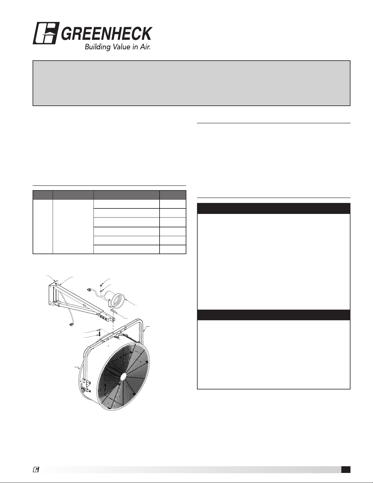
Model Use on Model Includes Quantity
(A) Dock Arm with Pivot Bracket 1
(B) Light Fixture 1
MAC-DA MAC-18-339-B4-J1
Pivot
Bracket
A
C) Z-Clip 1
(D) 1/2” Flat Washer 2
(E) 1/2 x 3” Bolt 1
(F) Nylok Nut 1
F
D
B
Unpacking
1. Inspect for any damage that may have occurred
during transit.
2. Shipping damage claim must be filed with carrier.
3. Check all parts listed are accounted for.
General Safety Information
WARNING:
To reduce the risk of fire, electrical shock, or injury to
persons, observe the following:
a. Use this unit only in the manner intended by the
manufacturer. If you have questions, contact the
manufacturer.
b. Before servicing or cleaning unit, switch power off
at service panel and lock the service disconnecting
the means to prevent power from being switched
on accidentally. When the service disconnecting
means cannot be locked, securely fasten a
prominent warning device, such as a tag, to the
service panel.
D
E
Air Circulator Tube
Figure 1 — Dock Arm Installation
®
C
Model MAC-CM-S
To reduce the risk of electric shock, do not expose to
WARNING:
water or rain.
1. Read and follow all instructions and cautionary
markings.
2. Disconnect all power before installing or servicing.
3. Follow all local safety codes in the United States
and Canada, as well as the Occupational Safety
and Health Act (OSHA) in the United States.
Dock Arm Kit
1
Page 2
Assembly and Installation
WARNING
Installation and troubleshooting to be performed only
by qualified person(s).
CAUTION
Support fan securely during assembly and installation.
1. Attach ceiling mount kit to the air circulator using
the instructions provided with the ceiling mount
accessory.
2. Locate the nearest wall stud for the desired
mounting location.
NOTE:
The recommended location for the electrical outlet is
directly below the wall mount pivot bracket.
3. Mount the pivot bracket on the dock arm(A) to a
structurally adequate wall using (4) appropriate
fasteners (by others).
4. Raise the fan to the dock arm and insert the 1/2 x
3” bolt(E) and washer(D) through the ceiling mount
bracket and dock arm. Refer to Figure 1.
5. Add Z-Clip(C) and light fixture(B). Fasten with
washer(D) followed by nylok nut(F). Back off nut 1/4
turn to allow fan movement.
IMPORTANT:
Do not assemble without Z-Clip as this is designed to
prevent cord damage when rotating light.
6. Install flood lamp (by others). Depress the spring
loaded push-button in the back of the shade and
screw the lamp into socket until seated firmly. Slowly
release the push-button.
IMPORTANT:
Maximum wattage for light fixture is 300 watt.
7. Plug fan into the outlet closest to the toggle switch
on the dock arm. Route the fan cord in a loop to
prevent pinching. Plug light into remaining outlet on
dock arm.
Maintenance
CAUTION
To reduce the risk of injury, disconnect and lockout
power source before servicing. Always unplug the
power cord.
1. Depending on the usage and severity, a regularly
scheduled inspection should be established.
2. Check for unusual noises when circulator is
running.
3. Periodically inspect and tighten all bolts, screws
and set screws.
Warranty
Greenheck warrants this equipment to be free from defects in material and workmanship for a period of one year from the
shipment date. Any units or parts which prove to be defective during the warranty period will be replaced at our option
when returned to our factory, transportation prepaid. Motors are warranted by the motor manufacturer for a period of one
year. Should motors furnished by Greenheck prove defective during this period, they should be returned to the nearest
authorized motor service station. Greenheck will not be responsible for any removal or installation costs.
As a result of our commitment to continuous improvement, Greenheck reserves the right to change specifications without notice.
AMCA Publication 410-96, Safety Practices for Users and
Installers of Industrial and Commercial Fans, provides
additional safety information. This publication can be
obtained from AMCA International, Inc. at www.amca.org.
®
Phone: (715) 359-6171 • Fax: (715) 355-2399 • E-mail: gfcinfo@greenheck.com • Website: www.greenheck.com
475367 • Dock Arm Kit Rev. 1, April 2012 Copyright 2012 © Greenheck Fan Corporation
2
Page 3

www.amca.org.
se puede obtener en AMCA International, Inc, en:
información de seguridad adicional. Esta publicación
ventiladores industriales y comerciales, proporciona
seguridad para usuarios y personal de instalación de
La publicación AMCA 410-96, Prácticas de
Valorizando el Aire.
2
475367 • Soporte para Instalacion en plafones • Mod. 1, de abril 2012 Copyright 2012 © Greenheck Fan
EE.UU. • Teléfono (715) 359-6171 • info@greenheck.com • greenheck.com
Saltillo, México • info@greenheckmexico.com • greenheck.com.mx
®
las especificaciones sin previo aviso.
Como resultado de nuestro compromiso de mejorar constantemente, Greenheck se reserva el derecho de cambiar
ningún costo de desmontaje o instalación.
devolver a la estación de mantenimiento de motores autorizada más cercana. Greenheck no será responsable de
Si se demuestra que los motores que proporcione Greenheck presentan defectos durante este período, se deben
previo pago de su transporte. Los motores están garantizados por su fabricante durante un período de un año.
durante el período de garantía se reemplazarán según nuestro criterio cuando se devuelvan a nuestra fábrica,
de un año a partir de la fecha de enváo.Todas las unidades o partes que se demuestre que presentan defectos
Greenheck garantiza que este equipo está libre de defectos de materiales y de mano de obra durante un período
Warranty
la luz.
diseñado para evitar el daño del cordón cuando se gire
No monte nada sin el sujetador en Z, el cual está
IMPORTANTE:
PRECAUCIÓN
los pernos, tornillos y tornillos de fijación.
3. Inspeccione y apriete de manera periódica todos
existen ruidos anormales.
2. Cuando esté funcionando el circulador, revise si
establecer un programa de inspección regular.
1. Según el uso y la intensidad del mismo, se debe
alimentación.
mantenimiento. Desconecte siempre el cable de
y bloquee la fuente de energía antes de realizar
Para reducir el riesgo de lesiones, desconecte
MANTENIMIENTO
brazo de acoplamiento.
Enchufe la luz en el tomacorriente restante en el
bucle para evitar que se produzcan rasgaduras.
acoplamiento. Pase el cordón del ventilador en un
cercano al interruptor de palanca en el brazo de
7. Enchufe el ventilador en el tomacorriente más
300 watts.
El vataje máximo para un dispositivo de luz es de
IMPORTANTE:
lentamente el pulsador.
hasta que esté firmemente asentada. Suelte
la pantalla y atornille la lámpara en el portalámparas
pulsador cargado por resorte en la parte trasera de
6. Instale la luz de inundación (de terceros). Presione el
movimiento del ventilador.
Nylok (F). Afloje la tuerca 1/4 de giro para permitir el
(B). Fije con la arandela (D) seguida por una tuerca
5. Acomode el sujetador en Z (C) y el dispositivo de luz
acoplamiento. Consulte la Figura 1.
través del soporte de montaje en cielo y el brazo de
introduzca el perno de 1/2 x 3” (E) y la arandela (D) a
4. Suba el ventilador hasta el brazo de acoplamiento,
(proporcionados por terceros).
adecuada utilizando (4) sujetadores adecuados
acoplamiento (A) en una pared estructuralmente
3. Monte el soporte del pivote en el brazo de
montaje de pared.
eléctrico está directamente bajo el soporte del pivote de
La ubicación recomendada para el tomacorriente
NOTA:
el lugar de montaje que desee.
2. Ubique el entramado de pared más cercano para
proporcionan con el accesorio de montaje en cielo.
de aire haciendo uso de las instrucciones que se
1. Conecte el juego de montaje en cielo al circulador
instalación.
Sujete firmemente el ventilador durante el montaje y la
ADVERTENCIA
realizarla sólo una persona calificada.
La instalación y la solución de problemas deberá
ADVERTENCIA
MONTAJE E INSTALACIÓN
Page 4

®
1
JUEGO DE BRAZO DE ACOPLAMIENTO
ESPAÑOL
Figure 1 — Dock Arm Installation
Figura 1 — Instalación del Brazo de Acoplamiento
sus siglas en inglés) de los Estados Unidos.
de Seguridad y Salud Ocupacionales (OSHA, por
los Estados Unidos y Canadá, además de la Ley
instalación o de realizar mantenimiento.
precaución.
ADVERTENCIA
servicio.
prominente, como una etiqueta, en el panel de
coloque firmemente un dispositivo de advertencia
bloquear los medios de desconexión del servicio,
active en forma accidental. Cuando no se puedan
los medios para evitar que la alimentación se
de servicio y bloquee el servicio desconectando
unidad, desconecte la alimentación en el panel
Si tiene dudas, comuníquese con el fabricante.
ADVERTENCIA
3. Respete todos los códigos de seguridad locales de
E
2. Desconecte todo el suministro eléctrico antes de la
Model MAC-CM-S
Modelo MAC-CM-S
C
D
1. Lea y siga todas las instrucciones y marcas de
exponga al agua ni a la lluvia.
B
Para reducir el riesgo de descargas eléctricas, no lo
D
F
(F) Tuerca Nylok 1
E) Perno de 1/2 x 3” 1
(D) Arandela Plana de 1/2” 2
(C) Sujetador en Z 1
(B) Dispositivo de Luz 1
b. Antes de realizar mantenimiento o limpiar la
1
a. Use esta unidad sólo como lo indica el fabricante.
Soporte del Pivote
(A) Brazo de Acoplamiento con
Incluye Cantidad
A
o lesiones a personas, respete lo siguiente:
Para reducir el riesgo de incendio, descarga eléctrica
de Aire
Modelo
Use en el
Tubo del Circulador
Air Circulator Tube
Bracket
Pivote
Pivot
Soporte del
MAC-DA MAC-18-339-B4-J1
Modelo
ESPECIFICACIONES
DIMENSIONES Y
SEGURIDAD GENERAL
(150 watts), no se incluye.
inundación mediana nº 2V411 (300 watts) o nº 4PL09
aparecen en la lista.
3. Revise que se incluyan todas las partes que
transporte a la empresa de transporte.
2. Se debe presentar una queja por daños de
durante el transporte.
1. Revise si existen daños que se hayan producido
DESEMBALAJE
capa pulverizada de poliéster amarillo. Use una luz de
y áreas de carga. Fabricados de acero con con una
camiones semirremolque, almacenes de depósitos
aire industriales (tamaños de 46 cm [18” ]) cerca de
Diseñado para el montaje de los circuladores de
ACOPLAMIENTO
JUEGO DE BRAZO DE
corporales odaños a la propiedad.
presteatención a toda la información de seguridad. Si no respeta las instrucciones, puede provocar lesiones
o dar mantenimiento al producto que se describe. Por su propia seguridad y la de aquellos que lo rodean,
Lea y guarde estas instrucciones para referencia futura. Lea detenidamente antes de ensamblar, instalar, operar
Manual de Instalación, Operación y Mantenimiento
Juego De Brazo De Acoplamiento
PN 475367
®
 Loading...