

Page 1
Document 458341
Model BDF
®
Belt Drive Duct Fan
Installation, Operation and Maintenance Manual
Please read and save these instructions for future reference. Read carefully before attempting to assemble, install,
operate or maintain the product described. Protect yourself and others by observing all safety information. Failure
to comply with instructions could result in personal injury and/or property damage!
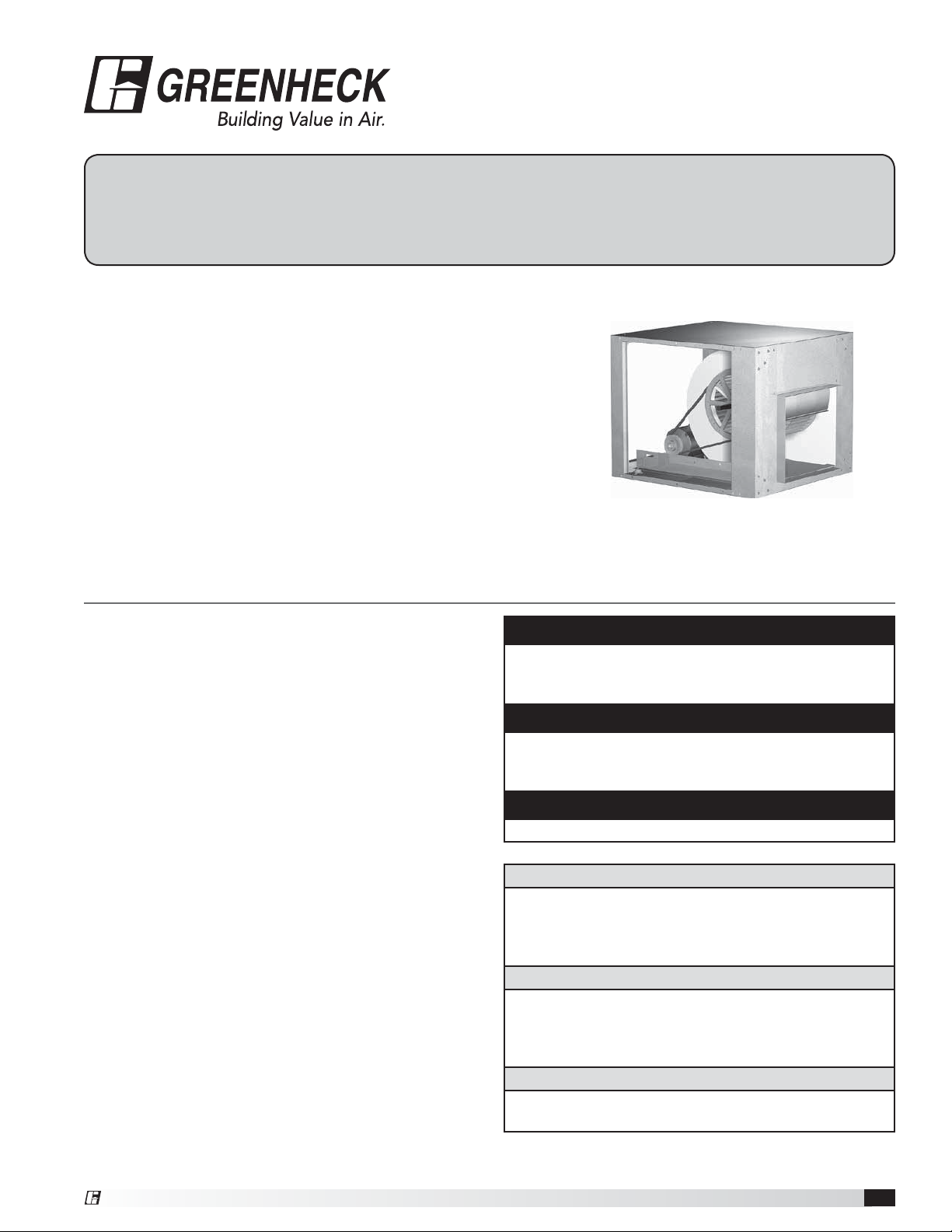
Model BDF Belt Drive Duct Fan
Model BDF is a belt drive duct supply, exhaust or return air fan. These
fans are specifically designed for inline applications. Performance
capabilities range up to 15,000 cfm (25,500 m
(747 Pa) of static pressure. BDF fans are available in seven sizes with
nominal wheel diameter ranging from 8 to 20inches (203to508 mm)
(080 - 200 unit sizes). Each fan shall bear a permanently affixed
manufacture’s engraved metal nameplate containing the model number
and individual serial number.
3
/hr) and up to 3.0in.wg
General Safety Information
Only qualified personnel should install this fan.
Personnel should have a clear understanding of these
instructions and should be aware of general safety
precautions. Improper installation can result in electric
shock, possible injury due to coming in contact with
moving parts, as well as other potential hazards. Other
considerations may be required if seismic activity
is present. If more information is needed, contact a
licensed professional engineer before moving forward.
1. Follow all local electrical and safety codes, as well as
the National Electrical Code (NEC) and the National
Fire Protection Agency (NFPA), where applicable.
Follow the Canadian Electric Code (CEC) in Canada.
2. The rotation of the wheel is critical. It must be free
to rotate without striking or rubbing any stationary
objects.
3. Motor must be securely and adequately grounded.
4. Do not spin fan wheel faster than max cataloged fan
RPM. Adjustments to fan speed significantly effects
motor load. If the fan RPM is changed, the motor
current should be checked to make sure it is not
exceeding the motor nameplate amps.
5. Do not allow the power cable to kink or come in
contact with oil, grease, hot surfaces or chemicals.
Replace cord immediately if damaged.
6. Verify that the power source is compatible with the
equipment.
7. Never open access doors to a duct while the fan is
running.
DANGER
Always disconnect, lock and tag power source before
installing or servicing. Failure to disconnect power
source can result in fire, shock or serious injury.
CAUTION
When servicing the fan, motor may be hot enough
to cause pain or injury. Allow motor to cool before
servicing.
CAUTION
Precaution should be taken in explosive atmospheres.
DANGER
Pour écarter les risques d’incendie, de choc électrique
ou de blessure grave, veiller à toujours débrancher,
verrouiller et étiqueter la source de courant avant
l’installation ou l’entretien.
ATTENTION
Lors de toute intervention sur la soufflante, le moteur
peut être suffisamment chaud pour provoquer une
douleur voire une blessure. Laisser le moteur refroidir
avant toute maintenance.
ATTENTION
Faire preuve de précaution dans les atmosphères
explosives.
®
Belt Drive Duct Fan 1
Page 2

Receiving
Upon receiving the product, check to ensure all items
are accounted for by referencing the delivery receipt or
packing list. Inspect each crate or carton for shipping
damage before accepting delivery. Alert the carrier of any
damage detected. The customer will make notification of
damage (or shortage of items) on the delivery receipt and
all copies of the bill of lading which is countersigned by
the delivering carrier. If damaged, immediately contact
your Greenheck Representative. Any physical damage
to the unit after acceptance is not the responsibility of
Greenheck Fan Corporation.
Unpacking
Verify that all required parts and the correct quantity
of each item have been received. If any items are
missing, report shortages to your local representative to
arrange for obtaining missing parts. Sometimes it is not
possible that all items for the unit be shipped together
due to availability of transportation and truck space.
Confirmation of shipment(s) must be limited to only items
on the bill of lading.
Handling
Move fan to desired location and determine position
of access panels and motor. Make sure inlet and
outlet have at least 2½ times the wheel diameter
(duct diameter) before any obstructions like an elbow
or transition. Attach the fan to a suitable framework
as specified, (hanging or base vibration isolators are
recommended). See Chart 1 on page 3 for physical
dimensions (Figure 1) and Chart 3 on page 3 for
dimensions of vibration isolators (Figure 3).
The motor’s amperage and voltage ratings must be
checked for compatibility to supply voltage prior to
final electrical connection. Supply wiring may be routed
through knockouts which are provided on the top and
bottom of each fan housing. Provide adequate wiring
to permit the access doors to open for servicing. Wiring
should be secured inside the fan to prevent interference
with the drive components. All wiring must conform to
local and national codes.
Storage
Fans are protected against damage during shipment. If
the unit cannot be installed and operated immediately,
precautions need to be taken to prevent deterioration of
the unit during storage. The user assumes responsibility
of the fan and accessories while in storage. The
manufacturer will not be responsible for damage during
storage. These suggestions are provided solely as a
convenience to the user.
Indoor - The ideal environment for the storage of fans
and accessories is indoors, above grade, in a low
humidity atmosphere which is sealed to prevent the entry
of blowing dust, rain or snow. Temperatures should be
evenly maintained between 30° to 110°F (-1° to 43°C)
(wide temperature swings may cause condensation
and “sweating” of metal parts). All accessories must be
stored indoors in a clean, dry atmosphere.
Remove any accumulations of dirt, water, ice or snow
and wipe dry before moving to indoor storage. To avoid
“sweating” of metal parts allow cold parts to reach room
temperature. To dry parts and packages use a portable
electric heater to get rid of any moisture buildup. Leave
coverings loose to permit air circulation and to allow for
periodic inspection.
The unit should be stored at least 3½ in. (89 mm) off the
floor on wooden blocks covered with moisture proof
paper or polyethylene sheathing. Aisles between parts
and along all walls should be provided to permit air
circulation and space for inspection.
Outdoor - Fans designed for outdoor applications may
be stored outdoors, if absolutely necessary. Roads or
aisles for portable cranes and hauling equipment are
needed.
The fan should be placed on a level surface to prevent
water from leaking into the fan. The fan should be
elevated on an adequate number of wooden blocks so
that it is above water and snow levels and has enough
blocking to prevent it from settling into soft ground.
Locate parts far enough apart to permit air circulation,
sunlight and space for periodic inspection. To minimize
water accumulation, place all fan parts on blocking
supports so that rain water will run off.
Do not cover parts with plastic film or tarps as these
cause condensation of moisture from the air passing
through heating and cooling cycles.
Fan wheels should be blocked to prevent spinning
caused by strong winds.
Inspection & Maintenance During Storage
While in storage, inspect fans once per month. Keep a
record of inspection and maintenance performed.
If moisture or dirt accumulations are found on parts,
the source should be located and eliminated. At each
inspection, rotate the wheel by hand ten to fifteen
revolutions to distribute lubricant on motor. If paint
deterioration begins, consideration should be given to
touch-up or repainting. Fans with special coatings may
require special techniques for touch-up or repair.
Machined parts coated with rust preventive should be
restored to good condition promptly if signs of rust
occur. Immediately remove the original rust preventive
coating with petroleum solvent and clean with lint-free
cloths. Polish any remaining rust from surface with
crocus cloth or fine emery paper and oil. Do not destroy
the continuity of the surfaces. Thoroughly wipe clean
with Tectyl
®
506 (Ashland Inc.) or the equivalent. For
hard to reach internal surfaces or for occasional use,
consider using Tectyl
®
511M Rust Preventive, WD-40®
or the equivalent.
Removing from Storage
As fans are removed from storage to be installed in their
final location, they should be protected and maintained
in a similar fashion until the fan equipment goes into
operation.
Belt Drive Duct Fan2
®
Page 3
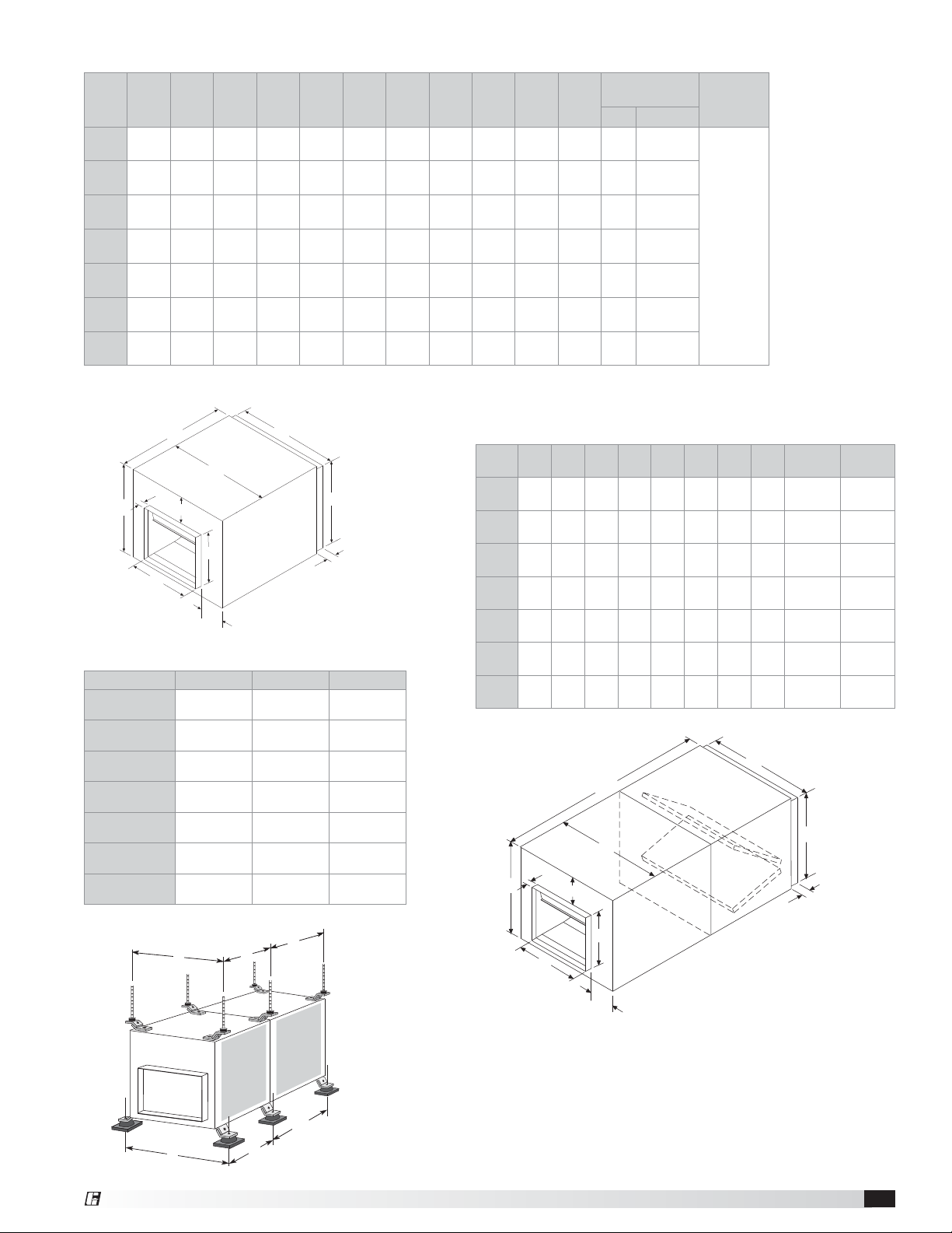
Chart 1: Fan Dimensions
Unit
Size
100
120
150
180
200
All dimensions in inches (millimeters) and weight is shown in pounds (kilograms).
*May be greater depending on motor. **Weight shown is largest cataloged Open Drip Proof motor.
80
90
AB
1
⁄4
181⁄2
23
(591)
(470)
1
⁄4
211⁄4
24
(616)
(540)
1
⁄4
223⁄4
26
(667)
(578)
271⁄4
33
(838)
(692)
3
⁄4
325⁄8
34
(883)
(829)
1
⁄4
413⁄4
40
(1022)
(1060)
1
⁄4
491⁄4
50
(1276)
(1251)
CDE FGH I JK*
157⁄8
153⁄16
(403)
183⁄4
(476)
203⁄4
(527)
223⁄4
(578)
273⁄4
(705)
313⁄4
(806)
393⁄4
(1010)
(386)
181⁄4
(464)
193⁄4
(502)
241⁄8
(613)
285⁄8
(727)
371⁄2
(953)
451⁄8
(1146)
1211⁄16
(322)
157⁄8
(403)
177⁄8
(454)
197⁄8
(505)
237⁄8
(606)
277⁄8
(708)
36
(914)
93⁄4
87⁄8
1
(248)
(225)
121⁄4
101⁄2
(311)
133⁄4
(349)
16
(406)
191⁄8
(486)
221⁄2
(572)
231⁄8
(587)
(267)
117⁄8
(302)
133⁄8
(340)
163⁄8
(416)
187⁄8
(479)
251⁄4
(614)
(25)
1
(25)
1
(25)
1
(25)
11⁄2
(38)
11⁄2
(38)
11⁄2
(38)
53⁄8
(137)
63⁄4
(171)
73⁄8
(187)
77⁄8
(200)
97⁄8
(251)
101⁄2
(
267
121⁄2
(318)
)
41⁄4
(108)
41⁄2
(114)
41⁄2
(114)
55⁄8
(143)
63⁄4
(171)
95⁄8
(244)
13
(330)
Approximate
Weight
Fan Filter Box
493⁄4
(1264)
71
(32)
547⁄8
517⁄8
753⁄8
851⁄4
92
(42)
107
(49)
144
(65)
223
(101)
307
(139)
565
(256)
(1394)
(1318)
639⁄16
(1614)
621⁄16
(1576)
(1915)
(2165)
32
(15)
42
(19)
52
(24)
70
(32)
97
(44)
134
(61)
174
(79)
Material
Thickness
20 gauge
(.912 mm)
A
B
2
C
I
G
F
D
E
H
Figure 1:
J
BDF Dimensions
Chart 3: Vibration Isolator Dimensional Data
Unit Size A C M*
80
90
100
120
150
180
200
All dimensions in inches (millimeters).
M* applies to optional filter box only.
3
⁄4
20
(527)
3
⁄4
21
(552)
3
⁄4
23
(603)
1
⁄2
30
(775)
32
(813)
3
⁄8
37
(949)
3
⁄8
47
(1203)
C
2211⁄16
(576)
255⁄8
(651)
271⁄8
(689)
315⁄8
(803)
35
(889)
44
(1118)
511⁄2
(1308)
M*
A
265⁄16
(668)
301⁄2
(775)
252⁄5
(645)
307⁄16
(773)
271⁄8
(689)
3415⁄16
(887)
36
(914)
Chart 2: Filter Option Dimensions
Unit
*KBCDEFGH
Size
80
90
100
120
150
180
200
All dimensions in inches (millimeters). *K is length of fan and filter box combined.
C
3
49
(1264)
7
54
(1394)
7
51
(1318)
9
63
(1614)
1
62
(1576)
3
75
(1915)
1
85
(2165)
F
⁄4
⁄8
⁄8
⁄16
⁄16
⁄8
⁄4
(1060)
(1251)
2
181⁄2
(470)
211⁄4
(540)
223⁄4
(578)
271⁄4
(692)
325⁄8
(829)
413⁄4
491⁄4
I
157⁄8
(403)
183⁄4
(476)
203⁄4
(527)
223⁄4
(578)
273⁄4
(705)
313⁄4
(606)
393⁄4
(1010)
G
K*
B
153⁄16
(386)
181⁄4
(464)
193⁄4
(502)
241⁄8
(613)
285⁄8
(727)
371⁄2
(953)
481⁄8
(1222)
1211⁄16
(322)
157⁄8
(403)
177⁄8
(454)
197⁄8
(505)
237⁄8
(604)
277⁄8
(708)
36
(914)
93⁄4
(248)
121⁄4
(311)
133⁄4
(349)
16
(406)
191⁄8
(486)
221⁄2
(572)
231⁄8
(587)
87⁄8
(225)
101⁄2
(267)
117⁄8
(302)
133⁄8
(340)
163⁄8
(416)
187⁄8
(479)
251⁄4
(641)
(25)
(25)
(25)
11⁄2
(38)
(25)
11⁄2
(38)
11⁄2
(38)
D
1
1
1
1
H
Filter
Size
16 x 20
(406 x 508)
20 x 25
(508 x 635)
20 x 20
(508 x 508)
12 x 25
(533 x 635)
16 x 20
(406 x 508)
20 x 25
(508 x 635)
16 x 25
(406 x 635)
E
Filter
Quantity
2
2
2
4
8
6
12
J
Figure 2:
BDF Filter Dimensions
Filter
BDF
Unit
Access
Panel
C
®
Box
Access
Panel
M*
A
Figure 3:
Vibration Isolator Dimensions
Belt Drive Duct Fan 3
Page 4

Pre-Startup Checks
1. Check all fasteners for tightness. The wheel should
rotate freely and not rub on the fan panel venturi.
Turn the fan on momentarily to check for unusual
vibration or noise. Do not run the fan more than
a few seconds without being connected to the
system for which it was designed. Motor overloading
and burnout may result from lack of system static
pressure.
2. Inlet and discharge collars are provided for duct
connection. The inlet panel is removable for
attaching optional filter box accessory.
3. Wheel Rotation: Direction of wheel rotation is
critical. Check wheel rotation by momentarily
energizing the unit. Improper rotation will result in
reduced airflow and pressure capabilities. Rotation is
always in the same direction as airflow at the outlet.
See housing and wheel examples in Figure 4.
O
I
N
T
A
T
O
R
AIRFLOW
O
I
N
T
A
T
O
R
AIRFLOW
6. Belt tension can be adjusted by loosening four
fasteners (marked “R”, Figure 6) on the drive frame.
The motor plate slides on the slotted adjusting arms.
Belt tension should be adjusted to allow 1/64 inch
of deflection per inch of belt span. For example, a
15 inch belt span should have 15/64inch (or about
1/4 inch) of deflection with moderate thumb pressure
at mid-point between pulleys (See Figure7).
Overtightening will cause excessive bearing wear
and noise. Too little tension will cause slippage at
startup and uneven wear.
R
NOTE:
Identical
fasteners on
opposing
side must
also be
loosened.
Figure 6
Figure 4:
Wheel Rotation Guide
WARNING
Correct direction of wheel rotation is critical. Reversed
rotation will result in poor air performance, motor
overloading and possible burnout.
AVERTISSEMENT
La turbine doit impérativement tourner dans le bon
sens. Une rotation en sens inverse entraînerait de
mauvaises performances de soufflage, une surcharge
du moteur voire un grillage du moteur.
4. Vibration Isolators: After fan is moved to desired
location, punch out the four knock-out holes which
are located on the unit top and bottom panels.
Assemble the brackets to the unit according to
the appropriate drawings on page 3 and refer to
respective parts list on page7. Make certain all
connectors are tight and that all washers are in.
5 If adjustments are made, it is very important to check
the pulleys for proper alignment. Misaligned pulleys
lead to excessive belt wear, vibration, noise and
power loss. (See Figure 5).
Deflection =
Figure 7
Belt Span
64
Belt Span
7. The adjustable motor pulley is factory set for the
RPM specified. Speed can be increased by closing
or decreased by opening the adjustable motor
sheave. Two groove variable pitch pulleys must be
adjusted an equal number of turns open or closed.
Any increase in speed represents a substantial
increase in the horsepower required by a unit. Motor
amperage should always be checked to avoid
serious damage to the motor when speed is varied.
Figure 5
Belt Drive Duct Fan4
WRONGCORRECT
WRONGWRONG
®
Page 5

Operation
Maintenance
1. Before starting up or operating fan, check all
fasteners for tightness. In particular, check the
setscrews in wheel hub (and pulleys, if applicable).
2. While in the OFF position or before connecting the
fan to power, turn the fan wheel by hand to be sure it
is not striking the venturi or any obstacle.
3. Start the fan and shut it off immediately to check
rotation of the wheel with directional arrow in the
motor compartment, see Figure 4.
4. When the fan is started, observe the operation and
check for any unusual noises.
5. With the system in full operation and all ductwork
attached, measure current input to the motor and
compare with the nameplate rating to determine if
the motor is operating under safe load conditions.
6. Keep inlets and approaches to fan clean and free
from obstruction.
Inspection
Inspection of the fan should be conducted at the
first 30 minute and 24 hour intervals of satisfactory
operation.
30 Minute Interval - Inspect bolts, setscrews and motor
mounting bolts. Adjust and tighten as necessary.
24 Hour Interval - Check all internal components and
inspect belt alignment and tension. Adjust and tighten
as necessary.
IMPORTANT
The fan has been checked for mechanical noises at
the factory prior to shipment. If mechanical noise
should develop, suggested corrective actions are
offered in the Troubleshooting section.
IMPORTANT
Over tightening will cause excessive bearing wear and
noise. Too little tension will cause slippage at startup
and uneven wear.
IMPORTANT
Adjust (tighten) belt tension after the first 24-48 hours
of operation.
DANGER
Always disconnect, lock and tag power source before
servicing. Failure to disconnect power source can
result in fire, shock or serious injury.
DANGER
Pour écarter les risques d’incendie, de choc électrique
ou de blessure grave, veiller à toujours débrancher,
verrouiller et étiqueter la source de courant avant
l’entretien.
IMPORTANT
Uneven cleaning of the wheel will produce an out of
balance condition that will cause vibration in the fan.
WARNING
This unit should be made non-functional when
cleaning the wheel or housing (fuses removed,
disconnect locked off).
AVERTISSEMENT
L’appareil doit être rendu non opérationnel lors du
nettoyage de la turbine ou du caisson (fusibles retirés,
sectionneur verrouillé).
Installation and maintenance are to be performed only
by qualified personnel who are familiar with local codes
and regulations and who are experienced with this type
of equipment.
Motor maintenance is generally limited to cleaning
and lubrication (where applicable). Cleaning should be
limited to exterior surfaces only. Removing dust buildup
on motor housing ensures proper motor cooling.
Greasing of motors is only intended when fittings are
provided. Many fractional horsepower motors are
permanently lubricated and should not be lubricated
after installation. Motors supplied with grease fittings
should be greased in accordance with manufacturers’
recommendations. Where motor temperatures do not
exceed 104°F (40°C), the grease should be replaced
after 2,000 hours of running time as a general rule.
Wheels require very little attention when moving clean
air. Occasionally, oil and dust may accumulate causing
imbalance. When this occurs the wheel and housing
should be cleaned to ensure smooth and safe operation.
All fasteners should be checked for tightness each time
maintenance checks are performed prior to restarting
unit.
A proper maintenance program will help these units
deliver years of dependable service.
®
Belt Drive Duct Fan 5
Page 6

Belt/Bearing Maintenance
1. Belts tend to stretch after a period of time. They
should be checked periodically for wear and
tightness. When replacing belts, use the same type
as supplied with the unit.
2. Matched belts should always be used on units with
multi-groove pulleys.
3. For belt replacement, loosen the tensioning device
enough to allow removal of the belt by hand. Do not
force belts on or off. This may cause cords to break,
leading to premature belt failure.
4. Once installed, adjust belts as shown in “Pre-Startup
Checks.”
5. Shaft bearings can be classified in two groups:
relubricating and non-relubricating. Bearings on sizes
80 through 180 are factory lubricated and require
no further lubrication under normal use (between
-20° and 180°F (-29°and 82°C) in a relatively clean
environment. Bearings on size 200 are relubricatable.
These bearings will require frequent lubrication.
Caution should be employed to prevent overpacking
or contamination.
6. Grease fittings should be wiped clean. The unit
should be in operation while lubricating. Extreme
care should be used around moving parts.
7. Grease should be pumped in very slowly until a slight
bead forms around the seal. A high grade lithium
base grease should be used.
Recommended Relubrication Frequency
in Months
NOTE: If unusual environment conditions exist (extreme
temperature, moisture or contaminants) more frequent
lubrication is required.
A good quality lithium base grease, conforming to NLGI
Grade 2 consistency, such as those listed here may be
used.
Table 1: Suggested Fan Bearing Greasing Intervals
Interval
(months)
1 to 3
3 to 6
6 to 12
12 to 18 Infrequent operation or light duty in clean atmosphere
Table 2: Grease Manufacturers
Manufacturer Grease (NLGI #2)
U.S. Electric Motors Grease No. 83343
Chevron U.S.A. Inc Chevron SRI Grease #2
Mobil Oil Corporation
Texaco, Inc.
Amoco Oil Co. Rykon Premium #2
Exxon Unirex N2
Shell B Shell Alvania #2
Heavy duty in dirty, dusty locations; high ambient
temperatures; moisture laden atmosphere; vibration.
12 to 24 hours per day, heavy duty, or if moisture is
present
8 to 16 hours per day in clean, relatively dry
atmosphere
Type of Service
Mobilith
Mobil 532
Premium BRB #2
Texaco Multifak #2
Troubleshooting
WARNING
Before taking any corrective action, make certain unit
is not capable of operation during repairs.
PROBLEM CAUSE CORRECTIVE ACTION
Wheel unbalance
Bad bearings Replace.
Excessive
noise or
vibration
Belts too tight or too loose Adjust tension, See Figure 7.
Wheel improperly aligned and
rubbing
Loose drive or motor pulleys Align and tighten. See “Pre-Startup Checks”, pages 4-5.
Foreign objects in wheel or housing Remove objects, check for damage or unbalance.
System resistance too high
Reduced
airflow
Unit running backwards Correct as shown in Figure 4.
Excessive dirt buildup on wheels Clean wheel.
Improper wheel alignment Center wheel on inlets.
Avant d’entreprendre toute action corrective, s’assurer
que l’appareil ne pourra pas fonctionner durant les
réparations.
Clean all dirt off wheel. Check wheel balance, rebalance in
place if necessary.
Center wheel on inlet.
Check system. Proper operation of backdraft or control
dampers, obstruction in ductwork, clean dirty filters.
AVERTISSEMENT
Belt Drive Duct Fan6
®
Page 7

Isolator Parts List
STANDING SUPPORT ISOLATOR HANGING SUPPORT ISOLATOR
Note: Top bracket
is reversible for
mounting unit 90°
from indicated.
(SQ and BSQ only)
4
1
5
7
5
6
2
2
3
5
6
Unit side panel
2
5
7
8
7
1
5
5
6
2
2
Unit side panel
4
6
1
5
4
3
6
5
8
1
2
6
5
7
5
5
Base fastener
(by installer)
No. Qty. Description BDF-80 thru 150 BDF-180 thru 200 No. Qty. Description BDF-80 thru 150 BDF-180 thru 200
18
28
34
48
520
612
74
84
Cadmium plated
hex head bolts
Cadmium plated
hex nuts
Cadmium plated
hex head bolts
Std. mount
bracket with two
7/16 in. holes
Cadmium plated
washer
Cadmium plated
lock washer
Cadmium plated
washer
Neoprene or
Spring Isolator
3/8 in. - 16 x 1 in. 3/8 in. - 16 x 1-1/4 in. 1 8
3/8 in. - 16 3/8 in. - 16 2 16
5/16 in. - 18 x 1 in. 3/8 in. - 16 x 1 in. 3 4
3/16 in. 1/4 in. 4 4
7/8 in. O.D. x
3/8in.I.D. x 1/16 in.
7/8 in. O.D. x
3/8inI.D. x 1/16 in.
3/8 in. 3/8 in. 6 12
1-3/8 in. O.D. x
9/16in. I.D. x 3/32 in.
1-3/8 in. O.D. x
9/16in. I.D. x 3/32 in.
Reference appropriate table below for
replacement Isolator(s)
Cadmium plated
hex head bolts
Cadmium plated
hex nuts
Std. mount
bracket with one
1/4 in. hole
Std. mount
bracket with two
7/16 in. holes
Cadmium plated
524
washer
Cadmium plated
lock washer
Cadmium plated
712
washer
Neoprene or
84
Spring Isolator
3/8 in. - 16 x 1 in. 3/8 in. - 16 x 1-1/4 in.
3/8 in. - 16 3/8 in. - 16
3/16 in. 1/4 in.
3/16 in. 1/4 in.
7/8 in. O.D. x
3/8in.I.D. x 1/16 in.
7/8 in. O.D. x
3/8in.I.D. x 1/16 in.
3/8 in. 3/8 in.
1-3/8 in. O.D. x
9/16in. I.D. x 3/32 in.
1-3/8 in. O.D. x
9/16in. I.D. x 3/32 in.
Reference appropriate table below for
replacement Isolator(s)
REPLACEMENT SPRING ISOLATOR(S)
MODEL FAN SIZE
BDF 80-90 100-200 150-180 200
BASE MOUNT FDS-1-70 GREEN FDS 1-120 GRAY FDS-1-220 BROWN FDS-1-370 ORANGE
HANGING SH-1-70 GREEN SH-1-125 GRAY SH-1-245 BROWN SH-1-370 ORANGE
REPLACEMENT NEOPRENE ISOLATOR(S)
MODEL FAN SIZE
BDF 80-100 120-150 180-200
BASE MOUNT R-1 GREEN R-2 BLACK R-2 RED
HANGING 40DUR BLACK 50DUR BLACK 50DUR BLACK
®
Belt Drive Duct Fan 7
Page 8

Parts List
Each fan bears a manufacturer’s nameplate with model number and serial number embossed. This information will
assist the local Greenheck representative and the factory in providing service and replacement parts. Before taking
any corrective action, make certain unit is not capable of operation during repairs.
CAUTION
A fan manufactured with an explosion resistant motor
does not certify the entire unit to be explosion proof.
Refer to ULListing Mark for the fans approved usage.
MOTOR
ACCE
SS
PANEL
ISOLATO
R
MOTOR
PULLE
SHA
Y
PULLE
CAUTION
La présence d’un moteur antidéflagrant sur un
ventilateur ne garantit pas que tout l’appareil est
antidéflagrant. Pour connaître les emplois autorisés
de l’appareil, voir son marquage de conformité UL.
SCROLL
FT
HOUSIN
BEL
DRIVE
S
UPPOR
Y
T
T
SHA
G
BEARIN
WHEEL
FT
G
Our Commitment
As a result of our commitment to continuous improvement, Greenheck reserves the right to change specifications
without notice.
Specific Greenheck product warranties are located on greenheck.com within the product area tabs and in the
Library under Warranties.
Greenheck’s Centrifugal Cabinet Fans catalog provides
additional information describing the equipment, fan
performance, available accessories, and specification data.
®
Phone: 715.359.6171 • Fax: 715.355.2399 • Parts: 800.355.5354 • E-mail: gfcinfo@greenheck.com • Website: www.greenheck.com
458341 • BDF, Rev. 5, September 2008 Copyright 2008 © Greenheck Fan Corporation8
AMCA Publication 410-96, Safety Practices for Users and
Installers of Industrial and Commercial Fans, provides
additional safety information. This publication can be obtained
from AMCA International, Inc. at www.amca.org.
 Loading...