

Page 1

Zone Pressure Touch (ZPT) Sensor - Standard Range
Installation and Operation Instructions
32215_ins_ZPT_SR_NT.pdf
rev. 05/09/2014
Product Identication
BAPI’s “Touch” Pressure Sensor is an accurate, rugged and economical solution for measuring and reporting duct/
building static pressure, room-to-room
differential pressure or air velocities/
volumes. The heart of the unit is a
micro-machined silicon pressure
sensor with excellent accuracy,
repeatability and stability.
The touch interface allows for quick
and easy menu driven set up of all
parameters including auto zero,
pressure ranges, output ranges, W.C.
or Pascal operation, and display
format of pressure, percent output or
“On”. You can also use the interface to
create custom ranges by adjusting the
upper and lower pressure endpoints.
Fig. 1: Zone Pressure Touch (ZPT), Enclosure Open and Closed
Specications
Power:
7 to 40 VDC (4 to 20 mA Output)
7 to 40 VDC or 18 to 32 VAC (0 to 5 or 1 to 5 VDC Output)
13 to 40 VDC or 18 to 32 VAC (0 to 10 or 2 to 10 VDC Output)
Power Consumption:
20 mA max, DC only at 4 to 20 mA Output
4.9 mA max DC at 0 or 1 to 5 VDC or 0 or 2 to 10 VDC Output
0.12 VA max AC at 0 or 1 to 5 VDC or 0 or 2 to 10 VDC Output
Load Resistance:
4 to 20 mA Output 850 Ω Maximum @ 24 VDC
0 to 5 VDC or 0 to 10 VDC output 1KΩ minimum
Customer Editable Parameters:
Auto-Zero, Pressure Range, Output Range, & Display
Accuracy at 72°F: ±0.25% of range
Stability: ±0.25% F.S. per year
Environmental Operation Range: 32 to 140°F (0 to 60°C)
Storage Temperature: -40 to 203°F (-40 to 95°C)
Temperature Error: 0.01% FS/°F (0.02% FS/°C)
(±5.0” WC @ -4 to 140°F [-20 to 60°C])
Overpressure: Proof 27.68” WC (1 PSI),
Burst 41.52” WC (1.5 PSI)
Wiring: 2 wires (4 to 20mA Current loop)
3 wires (AC or DC powered, Voltage out)
LED: Blue power and Auto-Zero indicator
Connector: Removable 3-terminal plug, 12 to 28 AWG
Humidity: 0 to 95% RH, non-condensing
Port Connection: 1 High Pressure & 1 Low Pressure for
push-on 1/4” tubing (1/8 to 3/16” I.D.)
Enclosure Material: UV-resistant Polycarb., UL94, V-0
Enclosure Rating: IP66, NEMA 4
Mounting: Four external tabs with holes for #10 screws
Ranges: Imperial or metric units available through setup
Setup Buttons: 3-Waterproof capacitive touch through
cover; Left Arrow, Enter, Right Arrow
Display: 4-Digit, 0.368 Inch (9.4 mm) tall
Agency: CE, RoHS
Table 1: Pressure Ranges
Inches Unit Pascal Unit
Range Pressure Range Pressure Range Pressure Range Pressure
71 0 to 1.00 in W.C 76 ± 1.00 in W.C. 81 0 to 250 Pa 86 ± 250 Pa
72 0 to 2.00 in W.C. 77 ± 2.00 in W.C. 82 0 to 300 Pa 87 ± 300 Pa
73 0 to 2.50 in W.C 78 ± 2.50 in W.C. 83 0 to 500 Pa 88 ± 500 Pa
74 0 to 3.00 in W.C. 79 ± 3.00 in W.C. 84 0 to 1,000 Pa 87 ± 1,000 Pa
75 0 to 5.00 in W.C. 80 ± 5.00 in W.C. 85 0 to 1,250 Pa 90 ± 1,250 Pa
Specications subject to change without notice.
Building Automation Products, Inc., 750 North Royal Avenue, Gays Mills, WI 54631 USA
Tel:+1-608-735-4800 • Fax+1-608-735-4804 • E-mail:sales@bapihvac.com • Web:www.bapihvac.com
1 of 5
Page 2
Zone Pressure Touch (ZPT) Sensor - Standard Range
Installation and Operation Instructions
32215_ins_ZPT_SR_NT.pdf
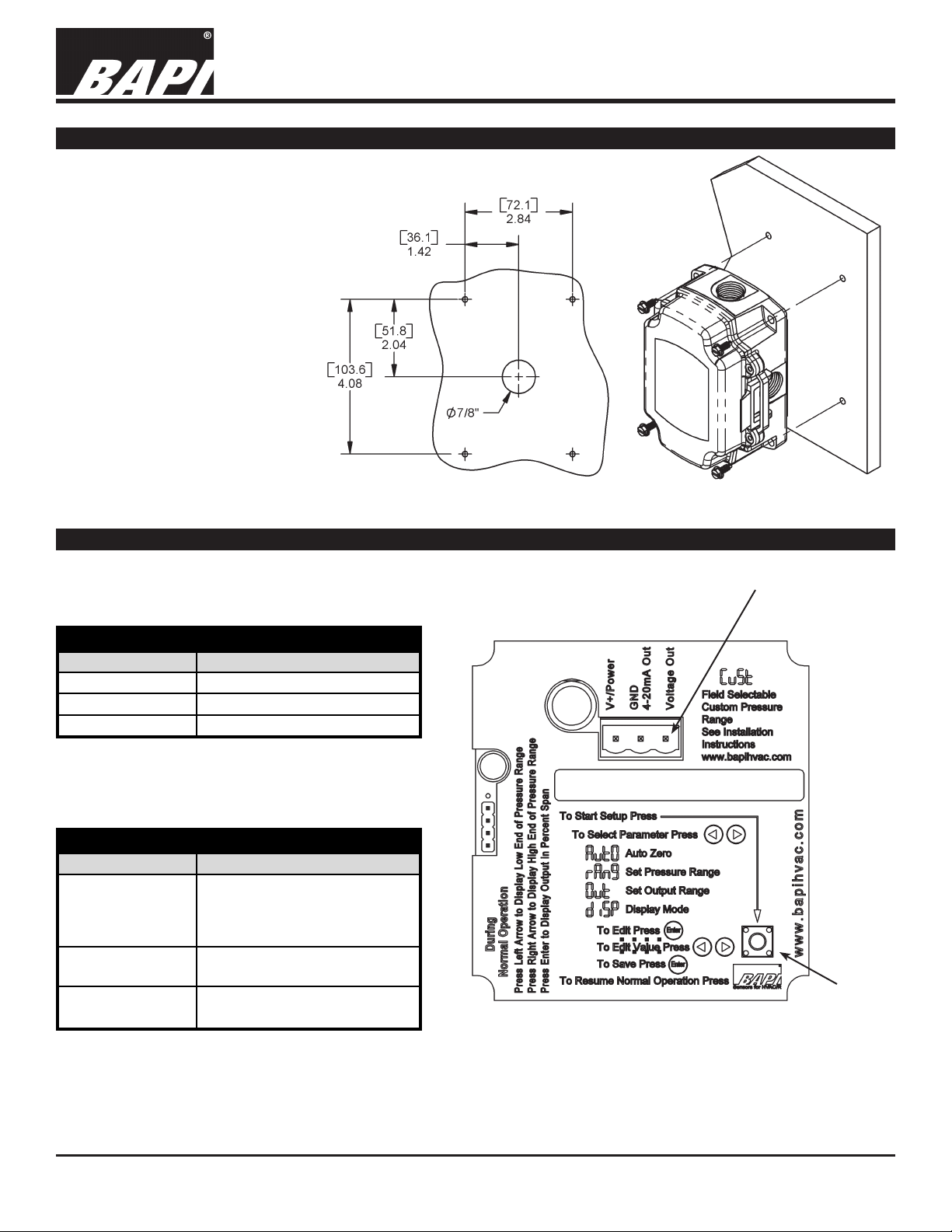
Mounting
Attach the unit to its mounting
surface with four #10 screws
through the holes in the
mounting feet. The preferred
mounting orientation is with the
pressure ports facing down.
Note: Remove Blue Dust Shields
from pressure ports before
use. Push tubing onto the port
nipple. Avoid kinks and holes in
the tubing or accuracy will be
affected.
Note: BAPI recommends using
#10 screws that require 5/32”
pilot holes
Note: Do not mount to a vibrating
Surface
Wiring Termination
rev. 05/09/2014
Fig 3: Mounting Screws LocationFig 2: Mounting Hole Pattern
Current Loop Connection
The ZPT unit requires DC voltage for 4 to 20 mA
current loop output, which is “two-wire” operation.
Current Loop Output Connection
Terminal Function
V+/Power 7 to 40 VDC
GND/4 to 20mA Out 4 to 20 mA Signal Output
Voltage Out Not used
Voltage Output Connection
The ZPT unit allows AC or DC voltage for voltage
output, which is “three-wire” operation.
Voltage Output Connection
Terminal Function
7 to 40 VDC or 18 to 32 VAC
V+/Power
GND/4 to 20mA Out
Voltage Out
(for 0 to 5 or 1 to 5 VDC Output)
13 to 40 VDC or 18 to 32 VAC
(for 0 to 10 or 2 to 10 VDC Output)
To controller Ground
[GND or Common]
Voltage Output, Pressure Signal,
referenced to GND
Note: Wiring plug removed for
Wiring Terminals
clarity. Wiring plug shown in Fig 1.
Fig 4: Wiring Terminals Inside Enclosure Cover
Setup
Start
Button
NOTE: The connectors use a rising block screw terminal to hold the wires. It is possible for the block to be in a
partially up position allowing the wire to be inserted under the block. Be sure that the connector screws are turned
fully counterclockwise before inserting the wire. Lightly tug on each wire after tightening to verify proper termination.
Specications subject to change without notice.
Building Automation Products, Inc., 750 North Royal Avenue, Gays Mills, WI 54631 USA
Tel:+1-608-735-4800 • Fax+1-608-735-4804 • E-mail:sales@bapihvac.com • Web:www.bapihvac.com
2 of 5
Page 3

Zone Pressure Touch (ZPT) Sensor - Standard Range
Installation and Operation Instructions
32215_ins_ZPT_SR_NT.pdf
rev. 05/09/2014
Normal Operation
During normal operation, the LCD shows the differential pressure between the high and low pressure ports of the
transmitter. The LCD allows enhanced troubleshooting by showing the actual differential pressure over the entire
operational pressure range of the sensor regardless of which pressure range is selected. For instance, if the 2.50
inch Water Column range is selected and 3.75 inches Water Column is present, the electrical output of the sensor
maxes out. The facility maintenance personnel looking at the sensor output can only tell that the pressure is greater
than 2.50 inches Water Column. With the display showing the actual pressure, it is easier for the maintenance
personnel to determine what is causing the error.
Additional Features:
• Pressing the left arrow button displays the low end pressure of the currently selected pressure range for 5
seconds.
• Pressing the enter button shows the electrical output in percent span for 5 seconds.
• Pressing the right arrow button displays the high end pressure of the currently selected pressure range for 5
seconds.
Note: If the display is set to OFF (see Parameter Setup below), pressing the enter button shows the current
pressure and a second press displays the electrical output in percent of span.
Parameter Setup
ENTERING AND EXITING PARAMETER SETUP MODE
To perform parameter setup (see setup ow chart, Fig 5, on the last page of this document):
• Open the enclosure cover and press the Setup Start Button on the lower right of the circuit board. (See Fig. 4)
• Close the cover, being careful not to touch the buttons or the BAPI logo.
• Press the right or left arrow buttons to select the entry icon of the parameter needing editing.
• Press the Enter button to select the parameter
• Edit the parameter according to the detailed instructions for each parameter below.
• Be sure that you are at the entry icon for each parameter edited to save the edit.
• To resume normal operation, press the BAPI logo.
Note: You may edit more than one parameter per session. All edits will hold through power downs.
AUTO-ZERO
Perform auto-zero after the unit is mounted and powered.
To auto-zero the BAPI ZPT, remove the tubing from the pressure ports (removing the normal pressure source).
Make sure that the pressure ports are sheltered from drafts, including the technician’s breath. Ideally the two ports
should be connected together with a short piece of tubing, making sure that there are no kinks in the tubing.
Entry Icon for Auto-Zero
• Enter the Auto-Zero Mode as described above in the “Entering and Exiting Parameter Setup Mode”.
• When the unit is in Auto-Zero Mode, press and release the Enter button. The display will show “OFF.”
• Press and release the Right or Left Arrow button until “On” is displayed.
• Press and release the Enter button. The display will show four dashes, “- - - -.”
• When the display shows “AutO,” auto-zero is complete and stored.
• Either resume normal operation or edit another parameter.
Continued on next page...
Specications subject to change without notice.
Building Automation Products, Inc., 750 North Royal Avenue, Gays Mills, WI 54631 USA
Tel:+1-608-735-4800 • Fax+1-608-735-4804 • E-mail:sales@bapihvac.com • Web:www.bapihvac.com
3 of 5
Page 4

Zone Pressure Touch (ZPT) Sensor - Standard Range
Installation and Operation Instructions
32215_ins_ZPT_SR_NT.pdf
rev. 05/09/2014
Parameter Setup continued...
PRESSURE RANGE SELECTION
Pressure range selection allows a technician to select inches Water Column or Pascals, uni-directional or
bi-directional pressure, one of ve standard pressure ranges (1.00”, 2.00”, 2.50”, 3.00”, 5.00”, 250Pa, 300Pa,
500Pa, 1,000Pa, or 1,250Pa) or input a custom range. The endpoints of the custom range must be between
-5.00 and 5.00 inches of Water Column or -1,250 and 1,250 Pascals. The custom range endpoints are selected
in increments of 0.1 inches of Water Column or 25 Pascals. The custom range “Hi” pressure endpoint may be at a
lower pressure than the “LO” pressure endpoint for reverse acting outputs.
Entry Icon
• Enter the Pressure Range Selection Mode as described in the “Entering and Exiting Parameter Setup Mode” on
the previous page.
• Press and release the Enter button. The display will show “in” for inches of Water Column or “PA” for Pascals.
Using the Left or Right Arrow buttons, select the desired units.
• Press and release the Enter button. The display will show one of the 5 standard ranges or “CuSt” for the custom
range. Using the Left or Right Arrow buttons, select the range, then press and release the Enter button.
■ If one of the standard rages was selected, the display will show “uni” or “–bi.” Using the Left or Right Arrow
buttons, select uni-directional or bi-directional pressure.
• Press and release the Enter button. When the display shows “rAng”, one of the standard ranges is
selected and stored.
• Either resume normal operation or edit another parameter.
■ If custom range was selected rather than a standard range, the display will show “Hi.”
• Press and release the Enter button. The display will show the current high end of the custom pressure
range. Using the Left or Right Arrow buttons, select the high end pressure desired.
• Press and release the Enter button. The display will show “LO.”
• Press and release the Enter button. The display will show the current low end of the custom pressure
range. Using the Left or Right Arrow buttons select the low end pressure desired.
• Press and release the Enter button. When the display shows “rAng,” the custom range is dened and
stored.
• Either resume normal operation or edit another parameter.
OUTPUT RANGE AND OUTPUT DAMPENING SELECTION
Output range selection allows a technician to select one of four voltage outputs (0 to 5 VDC, 0 to 10 VDC, 1 to 5
VDC, or 2 to 10 VDC) or the 4 to 20 mA current output. This area is also used to to set the output dampening to fast
or slow. Fast dampening has a time constant of 0.5 seconds. Slow dampening has a time constant of 4 seconds.
Entry Icon
• Enter the Output Range Selection Mode as described in the “Entering and Exiting Parameter Setup Mode” on
the previous page.
• Press and release the Enter button. The display will show the current output range. Using the Left or Right
Arrow buttons, select the output range desired.
• Press and release the Enter button. The display will show the current output dampening. Using the Left or Right
Arrow buttons, select “FASt” or “SLO.”
• Press and release the Enter button. When the display shows “Out,” the output range is selected and stored.
• Either resume normal operation or edit another parameter.
Continued on next page...
Building Automation Products, Inc., 750 North Royal Avenue, Gays Mills, WI 54631 USA
Tel:+1-608-735-4800 • Fax+1-608-735-4804 • E-mail:sales@bapihvac.com • Web:www.bapihvac.com
Specications subject to change without notice.
4 of 5
Page 5

Zone Pressure Touch (ZPT) Sensor - Standard Range
Installation and Operation Instructions
32215_ins_ZPT_SR_NT.pdf
rev. 05/09/2014
Parameter Setup continued...
DISPLAY ON OR OFF
Setting the display to “on” allows the display to show the current pressure reading during normal operation. Setting
the display to “OFF” prevents a casual observer from seeing the pressure reading during normal operation. All the
observer will see is the word “On,” indicating that the pressure transmitter is functional. A knowledgeable user can
display the pressure range endpoints, current pressure reading, and the output percent of span by pressing the
arrow or enter buttons as described on page 3 in the Normal Operation “Additional Features” section.
Entry Icon
• Enter the Display On or Off Mode as described in the “Entering and Exiting Parameter Setup Mode” on the page
3.
• Press and release the enter button. The display will show the current display state, “On” or “OFF”. Using the
left or right arrow buttons, select the display state needed.
• Press and release the enter button. When the display shows “diSP,” the display mode is set and stored.
• Either resume normal operation or edit another parameter.
Diagnostics
POSSIBLE PROBLEMS:
LED does not light
POSSIBLE SOLUTIONS:
- Check power connections for proper power
Output not tracking pressure properly
- Remove pressure from ports and perform auto-zero procedure
- Check for proper pressure range selection
- Check for proper output range selection
Specications subject to change without notice.
Building Automation Products, Inc., 750 North Royal Avenue, Gays Mills, WI 54631 USA
Tel:+1-608-735-4800 • Fax+1-608-735-4804 • E-mail:sales@bapihvac.com • Web:www.bapihvac.com
Page 6

Installation and Operation Instructions
rev. 05/09/2014
5 of 5
Zone Pressure Touch (ZPT) Sensor - Standard Range
32215_ins_ZPT_SR_NT.pdf
Fig 5: Parameter Setup Flow Chart
 Loading...