

Page 1
®
Document 1016626
Variable Frequency Drive (VFD)
®
and Control Packages
Installation, Operation and Maintenance Manual
Please read and save these instructions for future reference. Read carefully before attempting to assemble, install,
operate or maintain the product described. Protect yourself and others by observing all safety information. Failure
to comply with these instructions will result in voiding of the product warranty and may result in personal injury
and/or property damage.
VFD and Control Packages Availability
The speed control for fans provides a closed loop
variable frequency drive (VFD) control based on a
sensor input. The VFD is preprogrammed for the motor,
incoming power and available with various sensors.
Customer supplied sensors may be used. The speed
control is ideal for locations where a simple closed-loop
control is required.
Fan Model
AX
FJC
FJI
QEI
QEID
TAUB
TAUD
TBI
TCB
TDI
VAB/S
VAD/S
Remote
Dial
Constant
Airflow
Constant
Pressure
By Others
DANGER
Always disconnect, lock and tag power source before
installing or servicing. Failure to disconnect power
source can result in fire, shock or serious injury.
CAUTION
When servicing the fan, motor may be hot enough
to cause pain or injury. Allow motor to cool before
servicing.
CAUTION
Precaution should be taken in explosive atmospheres.
DANGER
Pour écarter les risques d’incendie, de choc électrique
ou de blessure grave, veiller à toujours débrancher,
verrouiller et étiqueter la source de courant avant
l’installation ou l’entretien.
ATTENTION
Lors de toute intervention sur la soufflante, le moteur
peut être suffisamment chaud pour provoquer une
douleur voire une blessure. Laisser le moteur refroidir
avant toute maintenance.
ATTENTION
Faire preuve de précaution dans les atmosphères
explosives.
Variable Frequency Drive (VFD) and Control Packages 1
Page 2

®
Table of Contents
VFD and Control Packages Availability ...........................................................1
General Safety Information ....................................................................3
Receiving, Unpacking, Handling and Storage ....................................................3
Inspection and Maintenance During Storage ....................................................3
Removing from Storage .....................................................................3
Variable Frequency Drive .....................................................................4
Mounting ................................................................................4
Weathershield Mounting ....................................................................4
Electrical Installation .......................................................................5
Power Wiring Procedure ....................................................................5
Remote Dial Control .........................................................................6
Kit Includes ..............................................................................6
Remote Dial Mounting ......................................................................6
Control Wire Installation .....................................................................6
Setpoint Adjustment Procedure ...............................................................7
Constant Airflow Control ......................................................................8
Kit Includes ..............................................................................8
Pressure Transducer Mounting ...............................................................8
Pressure Transducer Plumbing ...............................................................8
Control Wire Installation .....................................................................8
Setpoint Adjustment Procedure ...............................................................9
Constant Pressure Control ...................................................................10
Kit Includes .............................................................................10
Pressure Probe Mounting ..................................................................10
Pressure Transducer Mounting ..............................................................10
Control Wire Installation ....................................................................11
Setpoint Adjustment Procedure ..............................................................11
Customer Supplied Sensor/VFD Only ....................................................Backcover
Kit Includes ......................................................................Backcover
Our Commitment ....................................................................Backcover
Variable Frequency Drive (VFD) and Control Packages2
Page 3

®
General Safety Information
Only qualified personnel should install this unit. Personnel should have a clear understanding of these instructions,
the VFD manufacturer instructions, and be aware of general safety precautions. Improper installation can result
in electric shock, possible injury from contact with moving parts, as well as other potential hazards. Other
considerations may be required if high winds or seismic activity is present. If more information is needed, contact a
licensed professional engineer before moving forward.
1. Follow all local electrical and safety codes, as well as the National Electrical Code (NEC) and the National Fire
Protection Agency (NFPA), where applicable. Follow the Canadian Electric Code (CEC) in Canada.
2. Do not allow the power cable to kink or come in contact with oil, grease, hot surfaces or chemicals. Replace cord
immediately if damaged.
3. Verify that the power source is compatible with the equipment.
4. For liquid tight applications, use appropriate sized liquid tight conduit.
Receiving
Upon receiving the product, check to ensure all items are accounted for by referencing the delivery receipt or
packing list. Inspect each crate or carton for shipping damage before accepting delivery. Alert the carrier of any
damage detected. The customer will make a notation of damage (or shortage of items) on the delivery receipt and
all copies of the bill of lading which is countersigned by the delivering carrier. If damaged, immediately contact your
local representative. Any physical damage to the unit after acceptance is not the responsibility of manufacturer.
Unpacking
Verify that all required parts and the correct quantity of each item have been received. If any items are missing,
report shortages to your local representative to arrange for obtaining missing parts. Sometimes it is not possible
that all items for the unit be shipped together due to availability of transportation and truck space. Confirmation of
shipment(s) must be limited to only items on the bill of lading.
Handling
Handle in such a manner as to keep from scratching or chipping the coating. Damaged finish may reduce the ability
of the fan to resist corrosion.
Storage
Units are protected against damage during shipment. If the unit cannot be installed and operated immediately,
precautions need to be taken to prevent deterioration of the unit during storage. The user assumes responsibility of
the fan and accessories while in storage. The manufacturer will not be responsible for damage during storage. These
suggestions are provided solely as a convenience to the user.
The ideal environment for the storage of units and accessories is indoors, above grade, in a low humidity atmosphere
which is sealed to prevent the entry of blowing dust, rain or snow. Temperatures should be evenly maintained between
30° to 110°F (-1° to 43°C), as wide temperature swings may cause condensation and “sweating” of metal parts. All
accessories must be stored indoors in a clean, dry atmosphere.
Remove any accumulations of dirt, water, ice, or snow and wipe dry before moving to indoor storage. To avoid
“sweating” of metal parts, allow cold parts to reach room temperature. Use a portable electric heater to dry parts and
remove moisture build up. Leave coverings loose to permit air circulation and to allow for periodic inspection.
The unit should be stored at least 3-1/2 inches
paper or polyethylene sheathing. Aisles between parts and along all walls should be provided to permit air circulation
and space for inspection.
(89 mm)
off the floor on wooden blocks covered with moisture proof
Inspection and Maintenance During Storage
While in storage, inspect equipment once per month. Keep record of inspection and maintenance performed.
Clean if moisture or dirt accumulations are found on parts; then source should be located and eliminated.
Removing from Storage
As units are removed from storage to be installed in the final location, the units should be protected and maintained
in a similar fashion until the equipment goes into operation.
Prior to assembly and installation of the unit and system components, inspect the assembly to make sure it is in
working order. Check all fasteners and accessories for tightness.
Variable Frequency Drive (VFD) and Control Packages 3
Page 4
®
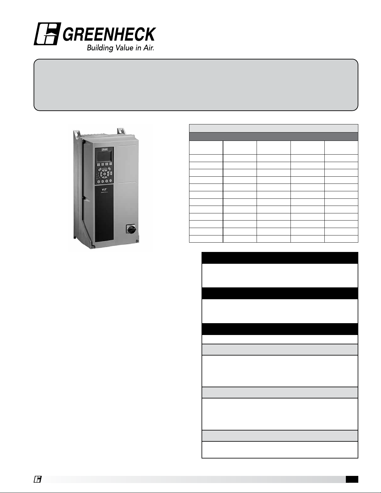
Variable Frequency Drive (VFD)
The VFD supplied is preprogrammed based on the
optional sensor input, motor supplied on the fan and
incoming power. The VFD supplies power to and
accepts the control signal from the optional sensor
to control fan speed. The VFD is housed in a NEMA3R rated enclosure suitable to be mounted indoors or
outdoors.
The VFD is not supplied with communication outputs to
building management or other control systems.
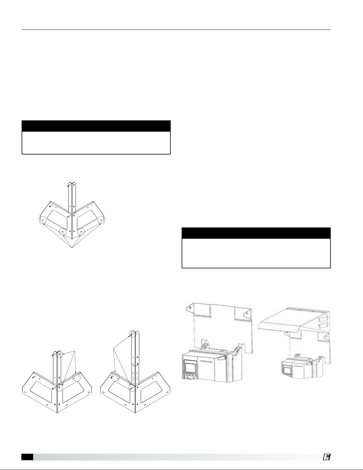
VFD Mounting Using Optional Corner
Brackets (FumeJet Only)
NOTE
The optional VFD roof curb corner mounting bracket
can be mounted on any corner of the roof curb and
VFD can be mounted on side B or C of the bracket.
1. Using holes A (See Figure 1) mount the VFD roof
curb corner mounting bracket on the appropriate
corner of the roof curb with field supplied fasteners.
Field Mounting
• The mounting hole pattern can be found in the
Danfoss manual supplied with the VFD.
• Place the VFD as near to the motor as possible,
keeping the motor cables as short as possible.
Maximum motor cable length to be less than 100 ft.
(30.5 m).
• Mount the VFD vertically to a solid structure; always
use the provided sheet metal backing plate.
• A minimum clearance of 9 in. (228.6 mm) above and
below, 3 in. (76.2 mm) on each side is required.
• If mounted outdoors, installation of the weathershield
is required.
Mounting VFD weathershield:
• Weathershield attaches to the top of the VFD using
M6x1 fasteners (supplied).
VFD Weathershield Mounting
The weathershield is only required if the VFD is mounted
outdoors.
1. Slide the bracket between the VFD mounting surface
and the back of the VFD (See Figure 3).
2. Tighten the upper mounting bolts to secure the
bracket and VFD.
Roof curb mounting holes (A)
Figure 1
2. The VFD mounting bracket has a telescoping corner
support that may need to be adjusted to fit the VFD
being used. Measure the distance between the
top and bottom mounting holes of the VFD being
mounted and adjust the support accordingly.
3. Using the supplied hardware, mount the VFD to the
three point mounting bracket using holes B or C
(See Figure 2).
VFD mounting holes
(B) (C)
NOTE
If the optional three-point mounting bracket is being
used, a nut and bolt will be required to secure the
weathershield bracket to the VFD on the unsupported
corner.
3. Slide the shield onto the bracket (See Figure 4).
4. Fasten the shield to the bracket with supplied
screws.
Figure 3 Figure 4
Lowered
Figure 2
4. Install weathershield if mounted outdoors.
Variable Frequency Drive (VFD) and Control Packages4
Raised
Page 5

®
Electrical Installation
• All wiring is by others.
• Use a dedicated ground wire for input power, motor power and control wiring. Do not ground one VFD to another
in a “daisy chain” fashion.
• Keep the grounding wire connections as short as possible.
• Improper grounding may cause premature motor failure.
• The VFD has an integrated fuse and disconnect.
• For liquid tight applications, use appropriate size liquid tight conduit.
• For replacement fuses, refer to included Danfoss Installation and Operation Manual (IOM).
• This manual focuses on the control setup from Greenheck. For more information on the VFD, programming
options, or BACnet integration please refer to the Danfoss website for current FC-102 manuals.
IMPORTANT
Always disconnect power before working on or near a unit. Lock and tag the disconnect switch and/or breaker to
prevent accidental power up.
Power Wiring Procedure
1. Remove the eight fasteners on the cover of the VFD using T20 Torx® or flat head screwdriver. An extension may
be needed to reach the fasteners. Remove the cover.
2. Connect incoming 3-phase AC input power to terminals T1, T2 and T3 on the master disconnect.
3. Connect ground cable to the nearest grounding terminal located on the body of the enclosure.
Local Control
Panel (LCP)
Control Wiring
Terminals
Location of
terminals may vary
96 97 98
Motor
Output
VFD
GRD
T1 T2 T3
GRD
3-phase
Input
4. Connect the 3-phase motor wiring to terminals 96 (U), 97 (V) and 98 (W).
5. Connect ground wire to the nearest grounding terminal located on the body of the enclosure.
6. Use a cable clamp to relieve pressure from connections.
7. Sensor wires will connect on terminal blocks below control pad. Control wires may need to be connected before
reinstalling cover.
8. Replace VFD cover reusing fasteners.
Variable Frequency Drive (VFD) and Control Packages 5
Page 6

®
Remote Dial Control
The VFD supplied is preprogrammed based on the optional sensor input, motor supplied on the fan, and incoming
power. The VFD supplies power to and accepts the control signal from the optional sensor to control fan speed. The
VFD is housed in a NEMA-3R rated enclosure suitable to be mounted indoors or outdoors.
The VFD is not supplied with communication outputs to building management or other control systems.
Kit Includes:
• NEMA-3R VFD including integral fuse and disconnect, with weathershield
• Remote dial with wall plate
1.06 in.
(27.0 mm)
1.00 in.
(25.4 mm)
0.88 in.
(22.2 mm)
2.75 in.
(69.9 mm)
4.50 in.
(114.3 mm)
Remote Dial Control
Remote Dial Mounting
• Remote dial control is for indoor use only.
• Locate the remote dial control within 100 ft. (30.5m)
of the VFD.
• The remote dial control may be mounted in a
standard 2x4 in. electrical junction box.
Control Wire Installation
IMPORTANT
Always disconnect power before working on or near a unit. Lock and tag the disconnect switch and/or breaker to
prevent accidental power up.
NOTE
When servicing the unit, VFD may be hot enough to cause pain or injury. Allow VFD to cool before servicing.
Keep control wires as short as possible [100 ft. (30.5m) or less] and separate from high power cables to minimize
interference.
1. Remove the eight fasteners on the VFD cover using T20 Torx® or flat head screwdriver. An extension may be
needed to reach the fasteners. Remove the cover to access wiring terminals.
2. When installing the control wires on the VFD, open the contact by inserting a small screwdriver into the slot
between the contact holes and push the screwdriver slightly upwards.
3. Connect the COM terminal from the remote dial control to terminal 55 on the VFD.
4. Connect the 24V terminal from the remote dial control to terminal 13 on the VFD.
5. Connect the 0-10V terminal from the remote dial control to terminals 53 and 54 on the VFD.
6. Reinstall the cover on the VFD.
m
m
0
1
Wire Insulation Removal Insert Wire in Terminal
Variable Frequency Drive (VFD) and Control Packages6
12
13
18
19
27
29
32
33
1
2
Page 7

®
Local Control
To 53 & 54
Panel (LCP)
53 54 55
Location of disconnect and
13
motor wiring will vary based
on model of VFD.
0-10V
COM
24V
Speed Control
To 55
To 13
Motor
Output
96 97 98
GRD
T1 T2 T3
GRD
3-phase
Input
VFD
Setpoint Adjustment Procedure
No adjustment within the VFD is needed.
1. To increase the fan speed, rotate the dial clockwise.
2. To decrease the fan speed, rotate the dial counterclockwise.
3. To turn the fan off, rotate the dial counterclockwise until the dial indicator points to zero.
Variable Frequency Drive (VFD) and Control Packages 7
Page 8

®
Constant Airflow Control
NOTE
Fan must be equipped with Sure-Aire™ to utilize
constant airflow control package.
The VFD supplied is preprogrammed based on the
optional sensor input, motor supplied on the fan and
incoming power. The VFD supplies power to and
accepts the control signal from the optional sensor
to control fan speed. The VFD is housed in a NEMA3R rated enclosure suitable to be mounted indoors or
outdoors.
The VFD is not supplied with communication outputs
to building management or other control systems. The
airflow setpoint is field adjustable using the local control
panel (LCP).
The Dwyer Magnesense MSII has a digital display and is
housed in a NEMA-4X enclosure suitable to be mounted
indoors or outdoors. The system calculates volume
based on differential static pressures measured with
Sure-Aire.
Kit Includes:
• NEMA-3R VFD including integral fuse and
disconnect, with weathershield
• Dwyer Magnesense MSII pressure transducer
• 25 ft. (7.6 m) of 1/4 in. (6.4 mm) nylon tubing
Pressure Transducer Mounting
• The pressure transducer is housed in a NEMA-4X
rated enclosure suitable to be mounted indoors or
outdoors.
• Locate the pressure transducer as close to the
Sure-Aire ports as possible.
• The pressure transducer should be mounted on a
vertical surface with the connections directed down
to prevent moisture from entering either the pressure
ports or the electrical cable entry. The diaphragm
must be vertical to minimize gravity effects.
• Attach the mounting flange to a flat surface. Do not
overtighten.
• Mount the pressure transducer higher than the
Sure-Aire termination plate to ensure that any
moisture or condensation drains back into the fan.
Control Wire Installation
IMPORTANT
Always disconnect power before working on or near
a unit. Lock and tag the disconnect switch and/or
breaker to prevent accidental power up.
NOTE
When servicing the unit, VFD may be hot enough
to cause pain or injury. Allow VFD to cool before
servicing.
Keep control wires as short as possible [100 ft. (30.5m)
or less] and separate from high power cables to
minimize interference.
1. Remove the eight fasteners on the VFD cover using
T20 ®® or flat head screwdriver. An extension may
be needed to reach the fasteners. Remove the cover
to access wiring terminals.
2. Remove the face cover of the pressure transducer by
rotating the face cover counterclockwise and pulling
outward.
3. When installing the control wires on the VFD, open
the contact by inserting a small screwdriver into
the slot between the contact holes and push the
screwdriver slightly upwards.
4. Connect terminal 1 from the pressure transducer to
terminal 53 and 54 on the VFD.
5. Connect terminal 2 from the pressure transducer to
terminal 55 on the VFD.
6. Connect terminal 3 from the pressure transducer to
terminals 13 on the VFD.
7. Reinstall the cover on the VFD and the pressure
transducer.
m
m
0
1
Wire Insulation Removal Insert Wire in Terminal
12
13
18
1
19
27
29
2
Local Control
Panel (LCP)
32
33
Pressure Transducer Plumbing
1. Use the supplied 1/4 in. (6.4 mm) nylon tubing to
connect the high port on the Sure-Aire termination
plate located on the fan to the (+) port on the
pressure transducer.
2. Use the supplied 1/4 in. (6.4 mm) nylon tubing to
connect the low port on the Sure-Aire termination
plate located on the fan to the (-) port on the
pressure transducer.
Variable Frequency Drive (VFD) and Control Packages8
2
1
3
To 13
To 55
To 53 & 54
Pressure Transducer
53 54 55
Location of disconnect and
13
motor wiring will vary based
on model of VFD.
96 97 98
GRD
Motor
Output
VFD
T1 T2 T3
GRD
3-phase
Input
Page 9

®
Setpoint Adjustment Procedure
The kit will arrive with the setpoint preprogrammed based on the fan order. Adjustment should only be made by
qualified personnel.
1. Using the LCP keypad, depress the Quick Menu key.
2. Using the up and down arrows, select Q1 My Personal Menu. Depress the OK button to select.
3. Using the up and down arrows, select 20-21 Setpoint 1. Depress the OK button to select.
4. The display will flash Access Denied and Please Enter a Password. Using the up, down, right and left arrows,
adjust the password to 00000200. Depress the OK button.
5. The display will flash Password Accepted.
6. Depress the OK button. Using the up, down, right and left arrows, adjust the Setpoint 1 to the new desired
setpoint. Depress the OK button.
7. Depress Status button to return to the system Status menu.
Variable Frequency Drive (VFD) and Control Packages 9
Page 10

®
Constant Pressure Control
STATIC PRESSURE PROBE (ASPIRATION) MOUNTING FLANGE
The VFD supplied is preprogrammed based on the optional sensor input, motor supplied on the fan, and incoming
power. The VFD supplies power to and accepts the control signal from the optional sensor to control fan speed. The
VFD is housed in a NEMA-3R rated enclosure suitable to be mounted indoors or outdoors.
The VFD is not supplied with communication outputs to building management or other control systems.
The pressure setpoint is field adjustable using the local control panel (LCP).
The pressure transducer, a Dwyer Magnesense MSII, has a range of ±28 in. water column (WC). The digital display is
housed in a NEMA-4X enclosure suitable to be mounted indoors or outdoors.
Kit Includes:
• NEMA-3R VFD including integral fuse and disconnect, with weathershield
• Dwyer Magnesense MSII pressure transducer
• 25 ft. (7.6 m) of 1/4 in. (6.4 mm) nylon tubing
• One duct static pressure probe
Pressure Probe Mounting
The position of the static pressure probe to get the best results depends on the layout of the system. Select a
location on the duct that is a minimum of 1-1/2 duct diameters upstream or downstream from any dimensional
change, elbow, damper, or other obstruction.
The pressure probe mounting location should be centrally located in the duct to prevent condensation from entering
the tube. Avoid mounting the pressure probe at the bottom of the duct.
1. Drill a 3/8 in. (9.5 mm) diameter hole at the location where
pressure measurement is desired.
2. Insert the pressure probe into hole.
3. Secure probe using the mounting holes in the mounting
flange of the pressure probe. Tighten screws until the
mounting flange is flush with mounting location and gasket
is compressed.
Pressure Transducer Mounting
• The pressure transducer is housed in a NEMA-4X rated
enclosure suitable to be mounted indoors or outdoors.
• Locate the pressure transducer within 100 ft. (30.5m)of the VFD. One hundred feet is the maximum control wire
length for this pressure transducer.
• The pressure transducer should be mounted on a flat vertical surface with the connections directed down to
prevent moisture from entering either the pressure ports or the electrical cable entry. The diaphragm must be
vertical to minimize gravity effects on the diaphragm.
• The pressure transducer should be mounted higher than the static pressure probe to ensure that any moisture or
condensation drains back into the duct.
• Pressure transducer plumbing options:
• Negative static pressure measurement. Connect the pressure probe to the negative (-) port, as indicated on the
transmitter. Leave positive (+) port open to atmosphere.
• Positive static pressure measurement. Connect the pressure probe to the positive (+) port, as indicated on the
transmitter. Leave negative (-) port open to atmosphere.
2.00 in.
(50.8 mm)
Static Pressure Probe
(Aspiration)
0.50 in.
(12.7 mm)
0.25 in. max. OD
(6.35 mm)
0.19 in. holes (4)
(4.8 mm)
1.00 in.
(25.4 mm)
Mounting
Flange
1.50 in.
(38.1 mm)
0.50 in.
(12.7 mm)
Variable Frequency Drive (VFD) and Control Packages10
Page 11

®
Control Wire Installation
IMPORTANT
Always disconnect power before working on or near
a unit. Lock and tag the disconnect switch and/or
breaker to prevent accidental power up.
NOTE
When servicing the unit, VFD may be hot enough
to cause pain or injury. Allow VFD to cool before
servicing.
Keep control wires as short as possible [100 ft. (30.5m)
or less] and separate from high power cables to
minimize interference.
1. Remove the eight fasteners on the VFD cover using
T20 Torx
be needed to reach the fasteners. Remove the cover
to access wiring terminals.
2. Remove the face cover of the pressure transducer by
rotating the face cover counterclockwise and pulling
outward to access the wiring terminals.
3. When installing the control wires on the VFD, open
the contact by inserting a small screwdriver into
the slot between the contact holes and push the
screwdriver slightly upwards.
4. Connect terminal 1 from the pressure transducer to
terminal 53 and 54 on the VFD.
5. Connect terminal 2 from the pressure transducer to
terminal 55 on the VFD.
6. Connect terminal 3 from the pressure transducer to
terminals 13 on the VFD.
7. Reinstall the cover on the VFD and the pressure
transducer.
®
or flat head screwdriver. An extension may
m
m
0
1
12
13
18
19
27
29
32
33
1
2
Wire Insulation Removal Insert Wire in Terminal
Local Control
Panel (LCP)
2
1
3
To 13
To 55
To 53 & 54
Pressure Transducer
53 54 55
Location of disconnect and
13
motor wiring will vary based
on model of VFD.
96 97 98
T1 T2 T3
GRD
Motor
Output
GRD
3-phase
Input
VFD
Setpoint Adjustment Procedure
The kit will arrive with the setpoint preprogrammed
based on the fan order. Adjustment should only be
made by qualified personnel.
1. Using the LCP keypad, depress the Quick Menu key.
2. Using the up and down arrows, select Q1 My
Personal Menu. Depress the OK button to select.
3. Using the up and down arrows, select 20-21
Setpoint 1. Depress the OK button to select.
4. The display will flash Access Denied and Please
Enter a Password. Using the up, down, right and left
arrows, adjust the password to 00000200. Depress
the OK button.
5. The display will flash Password Accepted.
6. Depress the OK button. Using the up, down, right
and left arrows, adjust the Setpoint 1 to the new
desired setpoint. Depress the OK button.
7. Depress Status button to return to the system Status
menu.
Variable Frequency Drive (VFD) and Control Packages 11
Page 12

Customer Supplied Sensor/VFD Only
The VFD supplied is preprogrammed based on the motor supplied on the fan and incoming power. The VFD can be
run in hand mode or field programmed using the local control panel (LCP). For details on programming the VFD, refer
to the Danfoss Programming Guide for VLT HVAC Drive FC 102 located at http://drives.danfoss.com/products/vlt/.
The VFD has a 10 VDC (15 mA) and a 24 VDC (130 mA) power supply to power auxiliary devices.
Kit Includes:
• NEMA-3R VFD including integral fuse and disconnect, with weathershield
Local Control
Panel (LCP)
Location of disconnect and
motor wiring will vary based
on model of VFD.
Motor
Output
96 97 98
GRD
T1 T2 T3
GRD
3-phase
Input
VFD
Our Commitment
As a result of our commitment to continuous improvement, Greenheck reserves the right to change specifications
without notice.
Product warranties can be found online at Greenheck.com, either on the specific product page or in the literature
section of the website at Greenheck.com/Resources/Library/Literature.
®
Phone: 715.359.6171 • Fax: 715.355.2399 • Parts: 800.355.5354 • E-mail: gfcinfo@greenheck.com • Website: www.greenheck.com
1016626 • VFD and Controls Packages, Rev. 2, December 2020 Copyright 2020 © Greenheck Fan Corporation12
 Loading...