

Page 1
Document 475405
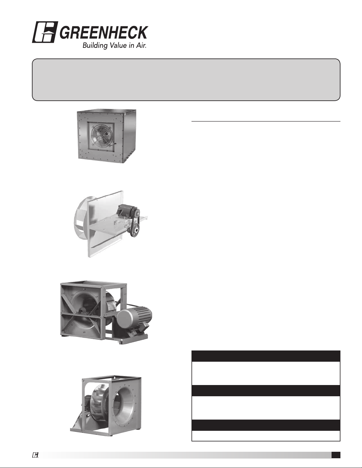
Model HPA, Model PLG,
®
Model APM, Model APH
Installation, Operation and Maintenance Manual
Please read and save these instructions for future reference. Read carefully before attempting to assemble, install,
operate or maintain the product described. Protect yourself and others by observing all safety information. Failure
to comply with instructions could result in personal injury and/or property damage!
General Safety Information
Only qualified personnel should install this fan.
Personnel should have a clear understanding of these
instructions and should be aware of general safety
precautions. Improper installation can result in electric
shock, possible injury due to coming in contact with
moving parts, as well as other potential hazards. Other
Model HPA - Housed Plenum Array
Model PLG - Plug
Model APM - Advanced Plenum Medium Pressure
considerations may be required if high winds or seismic
activity are present. If more information is needed,
contact a licensed professional engineer before moving
forward.
1. Follow all local electrical and safety codes, as well as
the National Electrical Code (NEC), the National Fire
Protection Agency (NFPA), where applicable. Follow
the Canadian Electric Code (CEC) in Canada.
2. The rotation of the wheel is critical. It must be free
to rotate without striking or rubbing any stationary
objects.
3. Motor must be securely and adequately grounded.
4. Do not spin fan wheel faster than max cataloged fan
rpm. Adjustments to fan speed significantly effects
motor load. If the fan RPM is changed, the motor
current should be checked to make sure it is not
exceeding the motor nameplate amps.
5. Do not allow the power cable to kink or come in
contact with oil, grease, hot surfaces or chemicals.
Replace cord immediately if damaged.
6. Verify that the power source is compatible with the
equipment.
7. Never open access doors to a duct while the fan is
running.
DANGER
Always disconnect power before working on or near a
fan. Lock and tag the disconnect switch or breaker to
prevent accidental power up.
Model APH - Advanced Plenum High Pressure
CAUTION
When servicing the fan, motor may be hot enough
to cause pain or injury. Allow motor to cool before
servicing.
CAUTION
Precaution should be taken in explosive atmospheres.
Housed Plenum Array, Plug and Plenum
1
Page 2

Table of Contents
General Safety Information . . . . . . . . . . . . . . . . . . . . . 1
Receiving . . . . . . . . . . . . . . . . . . . . . . . . . . . . . . . . . 2
Unpacking . . . . . . . . . . . . . . . . . . . . . . . . . . . . . . . . 2
Handling..................................2
Storage................................. 2-3
Inspection and Maintenance during Storage......3
Removing from Storage...................... 3
General Information
Unit and System Identification Tags . . . . . . . . . . . . 3
Pre-Installation Information ...................3
Electrical Disconnects .......................3
Moving Parts . . . . . . . . . . . . . . . . . . . . . . . . . . . . . . 3
Belt Guards ...............................3
Air Pressure and Suction . . . . . . . . . . . . . . . . . . . . . 4
Fans - Rigging and Lifting ......................4
Installation - Housed Plenum Array ............... 5
Installation - Plenum and Plug................... 5
Unhoused Wheels . . . . . . . . . . . . . . . . . . . . . . . . . . 5
Belt Guards ...............................6
Bases (Foundation and Isolation)............... 6
V-Belt Drives
Installation . . . . . . . . . . . . . . . . . . . . . . . . . . . . . . . . 7
Alignment of Pulleys and Belts . . . . . . . . . . . . . . . . 7
Radial Gap, Overlap and Wheel Alignment .........8
Field Coating Touch-Up Procedure ...............9
Electrical Connections.........................9
Unit Start-Up
Visual Inspection of Equipment ...............10
Check...................................10
Additional Steps for Initial Start-Up ............10
Vibration...................................11
Routine Maintenance
Fan Operation . . . . . . . . . . . . . . . . . . . . . . . . . . . . 11
Motors ..................................11
Belt Drive Maintenance . . . . . . . . . . . . . . . . . . . . . 12
Variable Frequency Drive Operation . . . . . . . . . . . 12
Shaft Bearings . . . . . . . . . . . . . . . . . . . . . . . . . . . . 12
Parts List ..................................13
Troubleshooting............................. 14
Maintenance Log............................ 15
Our Commitment ............................ 16
Receiving
Upon receiving the product check to ensure all items
are accounted for by referencing the delivery receipt or
packing list. Inspect each crate or carton for shipping
damage before accepting delivery. Alert the carrier
of any damage detected. The customer will make
a notation of damage (or shortage of items) on the
delivery receipt and all copies of the bill of lading which
is countersigned by the delivering carrier. If damaged,
immediately contact your Greenheck Representative.
Any physical damage to the unit after acceptance is not
the responsibility of Greenheck Fan Corporation.
Unpacking
Verify that all required parts and the correct quantity
of each item have been received. If any items are
missing report shortages to your local representative to
arrange for obtaining missing parts. Sometimes it is not
possible that all items for the unit be shipped together
due to availability of transportation and truck space.
Confirmation of shipment(s) must be limited to only
items on the bill of lading.
Handling
Fans are to be rigged and moved by the lifting brackets
provided or by the skid when a forklift is used. Location
of brackets varies by model and size. Handle in such
a manner as to keep from scratching or chipping the
coating. Damaged finish may reduce the ability of the
fan to resist corrosion. Fans should never be lifted by
the shaft, fan housing, motor, belt guard, windband or
accessories.
Storage
• Rotate fan wheel monthly and purge bearings once
every three months
• Energize fan motor once every three months
• Store belts flat to keep them from warping &
stretching
• Store unit in location which does not have vibration
• After storage period, purge grease before putting
fan into service
If storage of fan is in a humid, dusty or corrosive
atmosphere, rotate the fan and purge the bearings once
a month. Improper storage which results in damage to
the fan will void the warranty.
Fans are protected against damage during shipment. If
the unit cannot be installed and operated immediately,
precautions need to be taken to prevent deterioration of
the unit during storage. The user assumes responsibility
of the fan and accessories while in storage. The
manufacturer will not be responsible for damage during
storage. These suggestions are provided solely as a
convenience to the user.
The ideal environment for the storage of fans and
accessories is indoors, above grade, in a low humidity
atmosphere which is sealed to prevent the entry of
blowing dust, rain, or snow. Temperatures should
be evenly maintained between 30°F (-1°C) and
Housed Plenum Array, Plug and Plenum
2
Page 3
110°F (43°C) (wide temperature swings may cause
condensation and “sweating” of metal parts). All
accessories must be stored indoors in a clean, dry
atmosphere.
Remove any accumulations of dirt, water, ice or snow
and wipe dry before moving to indoor storage. To avoid
“sweating” of metal parts allow cold parts to reach room
temperature. To dry parts and packages use a portable
electric heater to get rid of any moisture build up. Leave
coverings loose to permit air circulation and to allow for
periodic inspection.
The unit should be stored at least 3½ in. (89 mm) off the
floor on wooden blocks covered with moisture proof
paper or polyethylene sheathing. Aisles between parts
and along all walls should be provided to permit air
circulation and space for inspection.
Inspection & Maintenance during Storage
While in storage, inspect fans once per month. Keep a
record of inspection and maintenance performed.
If moisture or dirt accumulations are found on parts,
the source should be located and eliminated. At each
inspection, rotate the wheel by hand ten to fifteen
revolutions to distribute lubricant on motor. If paint
deterioration begins, consideration should be given to
touch-up or repainting. Fans with special coatings may
require special techniques for touch-up or repair.
Machined parts coated with rust preventive should be
restored to good condition promptly if signs of rust
occur. Immediately remove the original rust preventive
coating with petroleum solvent and clean with lint-free
cloths. Polish any remaining rust from surface with
crocus cloth or fine emery paper and oil. Do not destroy
the continuity of the surfaces. Wipe clean thoroughly
with Tectyl® 506 (Ashland Inc.) or the equivalent.
For hard to reach internal surfaces or for occasional
use, consider using Tectyl® 511M Rust Preventive or
WD-40® or the equivalent.
Removing from Storage
As fans are removed from storage to be installed in their
final location, they should be protected and maintained
in a similar fashion, until the fan equipment goes into
operation.
Prior to fully assembling and installing the fan and
system components, inspect the fan assembly to make
sure it is in working order.
1. Check all fasteners, set screws, wheel, bearings,
drive, motor base and accessories for tightness.
2. Rotate the fan wheel by hand and assure no parts
are rubbing. Access to the wheel is obtained
through an access panel located on the side of the
fan housing.
3. Ensure proper wheel settings for radial gap and
alignment. See below.
General Information
To ensure a successful installation, the instructions in
this manual should be read and adhered to. Failure to
comply with proper installation procedures may void the
warranty.
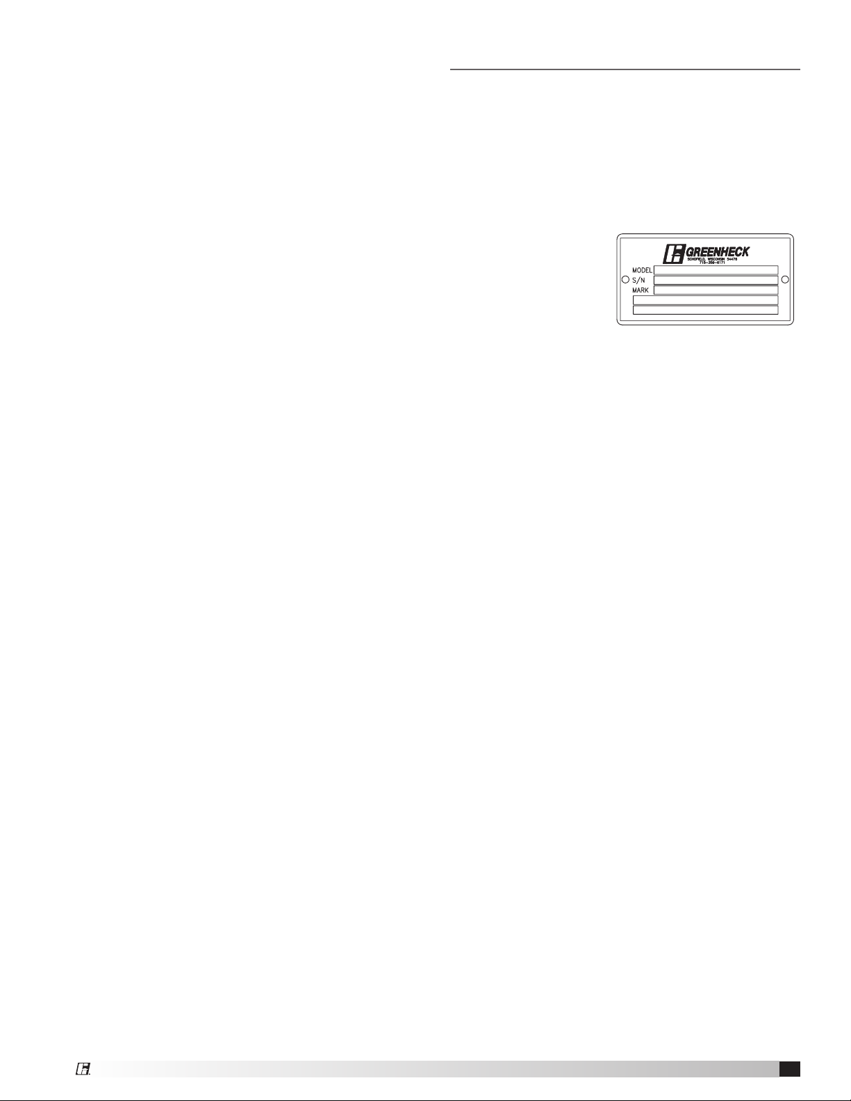
Unit and System Identification Tags
Each fan has a permanently affixed manufacturer’s
engraved metal nameplate containing the model
number and individual serial number.
The tag shown is
an example of an
identification nameplate
on the fan. The
information provides
general details about the
fan, as well as containing
specific information unique to the unit. When contacting
your Greenheck representative with future needs or
questions, please have the information on this label
available. Tags are mounted in an area which is clearly
visible, usually on the side of the fan cabinet.
Pre-Installation Information
Before installation, it is important to be certain the
mounting surface will bear the operating weight of the
unit. For proper unit operation, it is also important that it
be operated in a completely level position.
For further details on safety practices involving
industrial and commercial fans, please refer to AMCA
Publication410.
Electrical Disconnects
All fan motors should have disconnects located in close
visual proximity to turn off electrical service. Service
disconnects shall be locked-out when maintenance is
being performed.
Moving Parts
All moving parts must have guards to protect personnel.
Refer to local codes for requirements as to the number,
type and design. Fully secure fan wheel before
performing any maintenance. The fan wheel may start
“free wheeling” even if all electrical power has been
disconnected. Before the initial start-up or any restart,
check the following items to make sure that they are
installed and secure.
• Do not spin fan wheel faster than the maximum
cataloged fan rpm.
• Adjustments to fan speed significantly affects motor
load. If the fan RPM is changed, the motor current
should be checked to make sure it is not exceeding
the motor nameplate amps.
Belt Guards
Do not operate fans without proper protective devices in
place. Failure to do so may result in serious bodily injury
and property damage. Check local codes to ensure
compliance for all protective devices.
Housed Plenum Array, Plug and Plenum
3
Page 4
General Information - continued
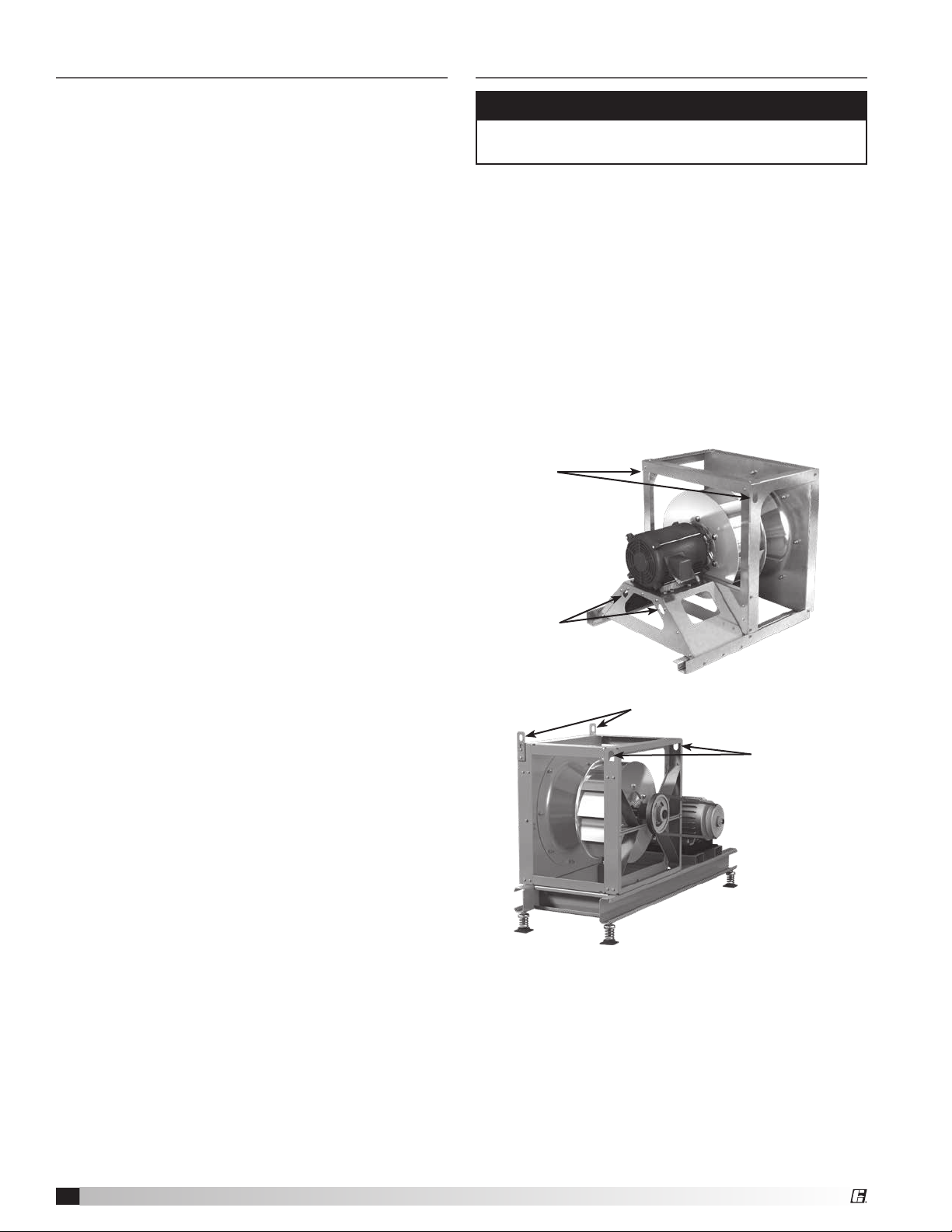
Fans – Rigging and Lifting
Air Pressure and Suction
In addition to the usual hazards associated with rotating
machinery, fans also create a dangerous suction at the
inlet. Special caution needs to be used when moving
around a fan, whether it is in operation or not. Before
start-up, make sure the inlet area is clear of personnel
and loose objects.
CAUTION
Fans should never be lifted by the shaft, motor, motor
cover or accessories.
Fans are to be rigged and moved by the lifting brackets
and/or lifting points provided or by the skid when a
forklift is used. Location of brackets varies by model
and size. Handle in such a manner as to keep from
scratching or chipping the coating. Damaged finish may
reduce ability of fan to resist corrosion. See coating
repair section of this manual for details involving touchup of damaged surfaces.
• Use standard lifting and rigging practices.
• ALL lifting brackets on each component must be
utilized at the same time.
• Fan to be kept level during lifting and installation.
APM
Lifting Point
Lifting Point
APH
Lifting Point
Lifting Point
Housed Plenum Array, Plug and Plenum
4
Page 5
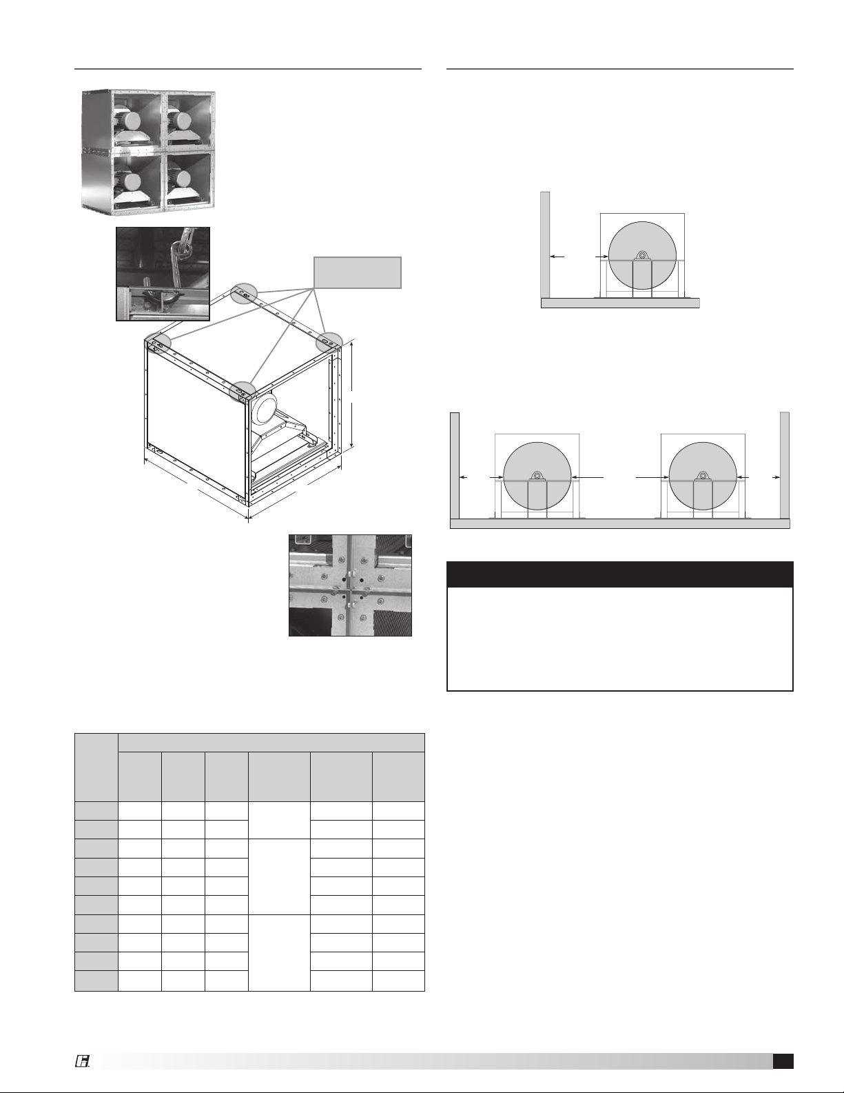
Installation - Housed Plenum Array
Installation - Plenum and Plug Fans
1. Carefully remove any crate
and packing materials.
2. Place the fan onto the
mounting structure using
the recommended lifting
points and hooking
Unhoused Wheels
Adjacent Walls - The distance between the fan and
walls or ceilings will effect the performance of the fan.
The recommended distance between the fan wheel
and any wall is a minimum of one-half wheel diameter.
Multiple walls reduce the performance even more.
method as shown. Lift
each fan individually into
it’s proper position.
One-half
wheel
Recommended
Lifting Points
diameter
Side by Side - When two or more plenum fans are
in parallel, there should be at least one fan diameter
spacing between the wheels. Applications with less
H
D
W
spacing will experience performance losses.
One-half
wheel
diameter
One
wheel
diameter
One-half
wheel
diameter
3. Bolt the fan to the floor and
adjacent fans using the inlet
and outlet mounting flanges.
The first layer of fans should
be securely installed before
installing the second layer of
fans.
4. Thin gasket material or caulk between fans is
recommended to prevent unwanted noise of air.
5. Do not exceed the maximum number of stacked
modules (refer to table).
Standard Housing
Wheel
Size
W H D^
15 29.00 29.00 32.06
16 31.50 31.50 37.00 256T 250
18 34.38 34.38 38.19
20 37.25 37.25 39.56 256T 340
22 41.00 41.00 42.19 286T 380
24 44.75 44.75 43.75 286T 425
27 48.94 48.94 47.56
30 53.81 53.81 48.94 326T 820
33 58.81 58.81 51.06 326T 960
36 64.56 64.56 51.06 326T 1100
Dimensions are in inches.
^Does not account for motors or accessories.
*Weight is less motor and drives.
Maximum
Stacked
Modules
4
3
2
Maximum
Motor
Frame
215T 215
256T 290
286T 680
Weight*
CAUTION
When installing a fan, ensure the proper protective
devices are used to protect personnel from moving
parts and other hazards. A complete line of protective
accessories are available from Greenheck including
inlet guards, outlet guards, belt guards, shaft guards,
protective cages, and electrical disconnects.
(lbs.)
Housed Plenum Array, Plug and Plenum
5
Page 6

Installation - Plenum and Plug Fans - continued
Belt Guards
Greenheck offers
various types of
customized belt
guards dependent
upon fan model,
arrangement and
motor position.
Motor position is
determined from
the drive side.
The various types of belt guards are shown in these
illustrations. If the guard is not purchased from
Greenheck, they must be supplied by the installer or
owner.
APH, Arr 1, 3
Motor Position (W/Z)
APH Arr 1, 3
Motor Position (X/Y)
Bases (Foundation and Isolation)
Critical to every fan installation is a strong, level foundation.
A reinforced poured concrete pad with a structural steel
base or inertia base provides an excellent foundation.
Structural bases must be sturdy enough, with welded
construction, to prevent flexing and vibration.
To eliminate vibration and noise from being transferred
to the building, vibration isolators should be used. The
fan is mounted directly on the isolation base and must
be supported for the entire length of the fan base angle
(Refer to the installation manual for structural bases if the
base was supplied by Greenheck). Isolators are installed
between the isolation base and the foundation.
After the fan, isolation base, and isolators are installed,
the entire assembly must be leveled. Position the level on
the isolation base, not the fan shaft, for proper leveling.
Additionally, the motor and fan shafts must be level and
parallel relative to each other for proper alignment.
APM, PLG Arr 9
If the belt guard is not factory mounted or was not
supplied by Greenheck, then it must be field mounted.
Brackets and mounting hardware are the responsibility
of the installer.
This figure illustrates the
suggested attachment
point for belt guard
mounting bracket locations.
These locations vary with
motor mounting position,
arrangement, and fan type.
The bearing supports and
fan structure are used in
most instances and when
the motor is not mounted
Motor Position: Side
Suggested Attachment Points
(shaded gray)
to the fan itself, a bracket should also be located near it.
This information is intended as only a guide and actual
field conditions may dictate another mounting location
for the guard brackets. Refer to local codes for securing
guarding.
Typical Fan on Isolation Base with Isolators
Housed Plenum Array, Plug and Plenum
6
Page 7

V-Belt Drives
MOTOR MOTOR
V-Belt Drive Installation
The V-belt drive components, when supplied by
Greenheck, have been carefully selected for this unit’s
specific operating condition.
IMPORTANT
Changing V-belt drive components could result
in unsafe operating conditions which may cause
personal injury or failure of the following components:
• Fan shaft
• Fan wheel
• Bearings
• V-belt
• Motor
1. Remove the protective coating from the end of the
fan shaft and assure that it is free of nicks and burrs.
2. Check fan and motor shafts for parallel and angular
alignment.
3. Slide sheaves on shafts, Do not
drive sheaves on as this may
result in bearing damage.
4. Align fan and motor sheaves
with a straight edge or
string, and tighten.
5. Place belts over sheaves.
Do not pry or force belts,
as this could result in
damage to the cords in
the belts.
6. Adjust the tension until the belts appear snug. Run
the unit for a few minutes (see section on Unit StartUp) and allow the belts to seat properly. Refer to
Greenheck’s Product Application Guide “Measuring
Belt Tension” for additional information.
7. With the fan off, adjust the belt tension by moving
the motor base. (See belt tensioning procedures in
the maintenance section of this manual). When in
operation, the tight side of the belts should be in a
straight line from sheave to sheave with a slight bow
on the slack side.
Aligning Sheaves
with a Straight Edge
Alignment of Pulleys and Belts
Check pulleys and belts for proper alignment to avoid
unnecessary belt wear, noise, vibration and power loss.
Motor and drive shafts must be parallel and pulleys in
line as shown.
CORRECT WRONG WRONG WRONG
The adjustable motor pulley is set at the factory for
the fan RPM specified by the customer. Fan RPM can
be increased by closing or decreased by opening the
adjustable motor pulley. Multi-groove variable pitch
pulleys must be adjusted an equal number of turns
open or closed. Any increase in fan speed represents a
substantial increase in load on the motor.
To avoid motor overheating and possible burnout, motor
load amperes should always be checked and compared
to nameplate rating when fan speed is increased.
Housed Plenum Array, Plug and Plenum
7
Page 8

Radial Gap, Overlap and Wheel Alignment
Efficient fan performance can be maintained by having the correct radial gap, overlap and wheel alignment. These
items should be checked after the fan has been in operation for 24 hours and before start-up after the unit has been
serviced.
PLG
Unit
Size
7 1
8 2
9 3
10 3
12 4
13 4
15 5
16 5
18 6
20 7
22 7
24 8
27 9
30 10
33 11
36 12
40 14
44 15
49 17
54 18
60 20
66 22
73 25
Inlet Cone to Backplate
A Dimension*
± Tolerance (in.)
3
3
3
7
7
7
3
13
5
7
13
15
±
⁄16
⁄16
⁄16
⁄16
⁄16
⁄16
⁄8
⁄16
⁄8
⁄16
9
⁄16
7
⁄16
3
⁄4
3
⁄16
9
⁄16
1
⁄8
⁄16
⁄16
7
⁄8
1
⁄2
1/8 30
±
1/8 36
±
1/8 81
±
1/8 87
±
1/8 102
±
1/8 113
±
1/8 127
±
1/8 138
±
1/8 162
±
3/16 178
±
3/16 198
±
1/4 219
±
1/4 240
±
3/8 268
±
3/8 291
±
3/8 324
±
3/8 360
±
3/8 395
±
1/2 435
±
1/2 478
±
1/2 532
±
1/2 581
±
1/2 648
A Dimension*
± Tolerance (mm)
±
3
±
3
±
3
±
3
±
3 1/8
±
3
±
3 1/8
±
3 3/16
±
3 3/16
±
5 1/4
±
5 1/4
±
6 5/16
±
6 3/8
±
10 3/8
±
10 7/16
±
10 7/16
±
10 1/2
±
10 9/16
±
13 5/8
±
13 5/8
±
13 3/4
±
13 7/8
±
13 1
*A dimension does not apply to partial width wheels.
APM, APH
Wheel Cone to Inlet Cone
Offset
± Tolerance (in.)
±
1/16 3
±
1/16 3
±
1/16 5
±
1/16 5
±
1/16 6
±
1/16 6
±
1/16 8
±
1/16 9.5
±
1/16 9.5
±
1/16 11
±
1/8 11
±
1/8 13
±
1/8 14
±
1/8 16
±
1/8 16
±
1/8 19
±
1/8
±
1/8 25
Offset
± Tolerance (mm)
±
1.5 7/16
±
1.5 7/16
±
1.5 7/16
±
1.5 7/16
±
1.5 7/16
±
1.5 7/16
±
1.5 7/16
±
1.5 9/16
±
1.5 9/16
±
1.5 9/16
±
3 9/16
±
3
±
3
±
3
±
3
±
3
22
±
3
±
3
Wheel Cone to Inlet Cone
Offset
± Tolerance (in.)
±
1/16 11
±
1/16 11
±
1/16 11
±
1/16 11
±
1/16 11
±
1/16 11
±
1/16 11
±
1/8 14
±
1/8 14
±
1/8 14
±
1/8 14
HPA
± Tolerance (mm)
Offset
±
1.5
±
1.5
±
1.5
±
1.5
±
1.5
±
1.5
±
1.5
±
1.5
±
1.5
±
1.5
±
3
Radial Gap (model PLG) is adjusted by loosening the
inlet cone bolts and centering the cone/ring on the
wheel. If additional adjustment is required to maintain
a constant radial gap, loosening the bearing bolts
and centering the wheel is acceptable as a secondary
option.
Overlap
A
Radial
Gap
PLG
Housed Plenum Array, Plug and Plenum
8
Wheel
Inlet
Cone
Overlap, or offset, (model APM, APH, HPA) is adjusted
by loosening the wheel hub from the shaft and moving
the wheel to the desired position along the shaft. The
transition between the inlet cone and wheel should be
as shown; there is a smooth feel to the profile when
moving from one component to the other.
Wheel
Offset
Inlet
Cone
APM, APH, HPA
Page 9

Field Coating Touch-Up Procedure
for Scratched Areas
Standard coating is Greenheck’s Concrete Grey,
RAL7023. The procedure below details the correct
method for repairing minor scratches in the coating.
TOUCH-UP PAINT REPAIR KIT CONTENTS
• One pint of Kem Kromik primer
- including a technical data sheet
• One pint of industrial enamel
- including a technical data sheet
• Four disposable foam brushes
• One sheet sandpaper
• Repair procedure details
1. Scuff affected area to be repaired using medium
sandpaper (provided) or medium scotch brite pad.
Feather the edges.
2. Clean affected area to be touched up using an
alkaline based cleaner and rinse.
3. Apply Kem Kromik primer using 1 inch foam brush
(provided). Follow technical data sheet instructions.
4. Allow primer to dry a minimum of 2 1/2 hours before
top coating.
5. Apply topcoat with industrial enamel using 1 inch
foam brush (provided). Follow technical data sheets
instructions. Allow painted units to air-dry and cure
before putting into service. See enclosed Technical
Data sheets for detailed drying and cure schedules
at different temperatures.
To order additional coating repair kits please reference
Greenheck’s part number HAZ2597, PNT FIELD REPAIR
KIT, RAL 7023 CONCRETE GREY kit. Please contact
factory with your fan’s serial number for colors other
than our standard.
Electrical Connections
Before electrical connections are made, the supply
voltage, phase and ampere capacity must be checked
for compatibility with the fan motor. In addition, the
supply wiring must be properly fused and conform to
local and national electrical codes. If the unit is supplied
with a safety disconnect switch, ensure proper wiring
to the fan motor. Be sure the disconnect is switched to
the “OFF” position before connecting supply wires. If
no disconnect is supplied, ensure the supply wire is not
live before connection. Supply wires are then connected
to the optional safety disconnect switch (if supplied) or
motor.
Housed Plenum Array, Plug and Plenum
9
Page 10

Unit Start-Up
N
WARNING
Disconnect and secure to the “Off” position all
electrical power to the fan prior to inspection or
servicing. Failure to comply with this safety precaution
could result in serious injury or death.
Visual Inspection of Equipment
The equipment type and arrangement should be
verified as ordered at once when it arrives at the jobsite.
When a discrepancy is found, the local Greenheck
Fan Corporation Sales Representative must be
notified immediately so that corrective action may
be investigated, also verify electrical conformance
to specifications. Unauthorized alterations and
unauthorized backcharges will not be recognized by
Greenheck Fan Corporation.
After the unit has been assembled, installed and all
utilities have been hooked up, the unit is now ready for
operation.
Check
Before starting the unit, check the following:
1. Confirm that building supply voltage matches the
voltage for which the unit is wired.
2. Disconnect and lock-out all power switches to fan.
See warning below.
3. Check all piping and wiring penetrations made by
contractors for water tightness. All penetrations
must be made watertight to prevent water damage
to the unit and building.
4. Check all fasteners, set screws and locking collars
on the fan, bearings, drive, motor base and
accessories for tightness.
5. Rotate the fan wheel by hand and assure no parts
are rubbing. Remove any dirt or debris that may
have accumulated during installation.
6. Check for bearing alignment and lubrication.
7. Check the V-belt drive for proper alignment and
tension.
8. Check all guarding (if supplied) for being securely
attached and not interfering with rotating parts.
9. Check all electrical connections for proper
attachment.
10. Check for obstructions and foreign material that
may damage the fan wheel.
Additional Steps for Initial Start-Up
1. Check for proper wheel
rotation by momentarily
energizing the fan. Rotation
is always determined by
viewing the wheel from
the drive side and should
correspond to the rotation
decal affixed to the unit.
Note: One of the most
frequently encountered
problems with centrifugal
fans is motors which are wired to run in the wrong
direction. This is especially true with 3-phase
installations where the motor will run in either
direction, depending on how it has been wired. To
reverse rotation of a 3-phase motor, interchange any
two of the three electrical leads. Single phase motors
can be reversed by changing internal connections as
described on the motor label or wiring diagram.
2. Fans with multi-speed motors should be checked on
low speed during initial start-up.
3. Check for unusual noise, vibration or overheating of
bearings. Refer to the “Troubleshooting” section of
this manual if a problem develops.
4. Grease may be forced out of the bearing seals during
initial start-up. This is a normal self-purging feature
of this type of bearing.
Airfoil Wheel Rotation
O
I
T
A
T
O
R
Always viewed from
the drive side.
Housed Plenum Array, Plug and Plenum
10
Page 11

Vibration
Routine Maintenance
Excessive vibration is the most frequent problem
experienced during initial start-up.
Left unchecked, excessive vibration can cause a
multitude of problems, including structural and/or
component failure.
Common Sources of Vibration
1. Wheel Unbalance
2. Drive Pulley Misalignment
3. Incorrect Belt Tension
4. Bearing
5. Mechanical Looseness
6. Faulty Belts
7. Drive Component Unbalance
8. Poor Inlet/Outlet Conditions
9. Foundation Stiffness
technician using vibration analysis equipment should be
consulted. If the problem is wheel unbalance, in-place
balancing can be done providing there is access to the
fan wheel. Any correction weights added to the wheel
should be attached securely.
Greenheck performs a vibration test on all centrifugal
fans before shipping. Three vibration readings are taken
on each bearing in the horizontal, vertical, and axial
directions.
The maximum allowable vibration for models PLG
and APM (belt and direct drive) and APH (belt drive)
is 0.15in/sec. peak velocity filter-in at the fan rpm per
AMCA Standard 204.
The maximum allowable vibration for model HPA (direct
drive) is 0.10 in/sec. and for model APH (direct drive)
is 0.08 in.sec. peak velocity filter-in at the fan rpm per
AMCA Standard 204.
These vibration signatures are a permanent record
of how the fan left the factory and are available upon
request.
Generally, fan vibration and noise is transmitted to other
parts of the building by the ductwork. To eliminate this
undesirable effect, the use of heavy canvas connectors
is recommended. If fireproof material is required,
FlexweaveTM 1000, Type FN-30 can be used.
Many of these
conditions can be
discovered by careful
observation. Refer to
the troubleshooting
section of this
manual for
corrective actions. If
observation cannot
locate the source of
vibration, a qualified
CAUTION
When performing any service to the fan, disconnect
the electrical supply and secure fan impeller.
Once the unit has been put into operation, a routine
maintenance schedule should be set up to accomplish
the following:
1. Lubrication of bearings and motor (see below).
2. Wheel, housing, bolts and set screws on the entire
fan should be checked for tightness.
3. Any dirt accumulation on the wheel or in the housing
should be removed to prevent unbalance and
possible damage.
4. Isolation bases should be checked for freedom
of movement and the bolts for tightness. Springs
should be checked for breaks and fatigue. Rubber
isolators should be checked for deterioration.
5. Inspect fan impeller and housing looking for fatigue,
corrosion, or wear.
When performing any service to the fan, disconnect the
electrical supply and secure fan impeller.
Fan Operation
All fans should be run every thirty (30) days, or at least
“bumped” every thirty days. It is preferred that each
fan is run as this causes all electrical and mechanical
components to get up to temperature, displacing any
formed condensation, redistributes load on bearings,
and redistributes grease in the bearings (motor and
shaft bearings).
CAUTION
• Always check the fan RPM when adjusting the
operating frequency. Do not exceed maximum
class fan RPM of the wheel.
• When operating conditions of the fan are to be
changed (speed, pressure, temperature, etc.),
consult Greenheck to determine if the unit can
operate safely at the new conditions.
Motors
Motor maintenance is generally limited to cleaning
and lubrication. Cleaning should be limited to exterior
surfaces only. Removing dust and grease build up on
the motor housing assists proper motor cooling. Never
wash-down motor with high pressure spray. Many
fractional motors are permanently lubricated for life
and require no further lubrication. Motors supplied with
grease fittings should be greased in accordance with
the manufacturer’s recommendations.
Housed Plenum Array, Plug and Plenum
11
Page 12

Belt Drive Maintenance
V-belt drives must be checked on a regular basis
for wear, tension, alignment and dirt accumulation.
Premature or frequent belt failures can be caused by
improper belt tension, (either too loose or too tight)
or misaligned sheaves. Abnormally high belt tension
or drive misalignment will cause excessive bearing
loads and may result in failure of the fan and/or motor
bearings. Conversely, loose belts will cause squealing
on start-up, excessive belt flutter, slippage, and
overheated sheaves. Either excessively loose or tight
belts may cause fan vibration.
When replacing V-belts on multiple groove drives all
belts should be changed to provide uniform drive
loading. Do not pry belts on or off the sheave. Loosen
belt tension until belts can be removed by simply lifting
the belts off the sheaves. After replacing belts, insure
that slack in each belt is on the same side of the drive.
Belt dressing should never be used.
Do not install new belts on worn sheaves. If the sheaves
have grooves worn in them, they must be replaced
before new belts are installed.
The proper tension for operating a V-belt drive is
the lowest tension at which the belts will not slip at
peak load conditions. Belt are adjusted by raising or
lowering the motor
pivot plate. For
Deflection =
Belt Span
64
initial tensioning,
the proper belt
deflection halfway
between sheave
centers is 1/64-inch
per each inch of belt
span.
Belt Span
For more information about measuring belt tension,
refer to Greenheck’s Product Application Guide, FA/12711, Measuring Belt Tension, found online at www.
greenheck.com in the library section.
Check belt tension before start up and after the first
24 hours of operation. The belt tension should also
be checked periodically thereafter.
Variable Frequency Drive Operation
For operation with Variable Frequency Drive (VFD),
always check motor amps when adjusting the operating
frequency. Motor may be sized for the original selected
operating speed under 60 Hz. Bypassing the VFD
or increasing the speed from this original selection,
even if less than 60 Hz, may cause motor overload or
failure. Consult factory–with fan serial number–before
increasing the upper limiting frequency.
Always check the fan rpm when adjusting the operating
frequency. Do not exceed maximum class fan rpm of
the wheel.
Shaft Bearings
The bearings for Greenheck fans are carefully selected
to match the maximum load and operating conditions
of the specific class, arrangement, and fan size. The
instructions provided in this manual and those provided
by the bearing manufacturer, will minimize any bearing
problems. Bearings are the most critical moving part
of the fan, therefore special care is required when
mounting them on the unit and maintaining them.
Refer to the following chart and the manufacturers
instructions for grease types and intervals for various
operating conditions. Never mix greases made with
different bases. This will cause a breakdown of the
grease and possible failure of the bearing.
Recommended Bearing Lubrication Schedule
Relubrication Schedule in Months*
Fan
RPM
To 250 12 12 12 12 12 12 10 8
500 12 12 11 10 8 7 5 4
750 12 9 8 7 6 4 3 2
1000 12 7 6 5 4 3 2 1
1250 12 6 5 4 3 2 1 .5
1500 12 5 4 3 2 1 .75
2000 12 3 3 2 1 .5 .25
2500 12 2 2 1 .5 .25
3000 12 2 1 .5 .25
3500 12 1 .5 .25
4000 12 .5 .25
5000 12 .25
Number
of shots**
* Lubrication interval is based on 12 hour day operation and
maximum 160˚F housing temperature.
For 24 hour per day operation, the interval should be cut in
half.
** Lubricant should be added with the shaft rotating and
until clean grease is seen purging from the bearing. The
lubrication interval may be modified based on the condition
of the purged grease. If bearing is not visible to observe
purged grease, lubricate with number of shots indicated for
bore size.
• For conditions including high temperatures, moisture, dirt
or excessive vibration, consult the factory for a specific
lubrication interval for your application.
• Lubricant should be a high quality lithium complex grease
conforming to NLGI Grade 2. Factory recommends Mobilux
EP-2 or synthetic Mobilith SHC100.
• The use of synthetic lubricants will increase lubrication
intervals by approximately three times.
• Storage periods of three months or longer require monthly
rotation of the shaft and purging grease prior to storage and
start-up.
1
⁄2 - 111⁄8 -
11⁄2
4 8 8 10 16 25 41 57
Bearing Bore (inches)
15⁄8 -
115⁄16 -
17⁄8
23⁄16
27⁄16
- 3
33⁄16 -
31⁄2
315⁄16 -
41⁄2
415⁄16 -
51⁄2
Housed Plenum Array, Plug and Plenum
12
Page 13

Parts List
Model HPA - Housed Plenum Array
Wheel Isolators
4 per fan
Motor
Drive
Frame
Inlet
Companion
Flange
Inlet Collar
Inlet Flange
(punched)
Housing
Inlet Venturi
Backward-Inclined
Model PLG - Plug
Heat Slinger
Insulated
Plug
Wheel
Motor
Belt Guard
Shaft Guard
Belt(s) &
Pulley
Model APM - Advance Plenum Medium Pressure
Arr. 3
All similar wire guarding comprises the
Protective Cage, 4 sided
Inlet
Flange
Inlet
Guard
Inlet Cone
Opposite
Drive Side
Bearing
Airfoil Wheel
Motor Pulley
(driver)
Shaft Pulley
Shaft
Drive Side
Bearing
Belt(s)
(driven)
Belt
Guard
Model APH - Advanced Plenum High Pressure
Arr. 4
All similar wire guarding comprises the
Protective Cage, 4 sided
Airfoil Wheel
Inlet Cone
Motor
Inlet Flange
Inlet Guard
Other arrangements will have variations in motor mounting positions.
Housed Plenum Array, Plug and Plenum
13
Page 14

Troubleshooting
Problem Cause Corrective Action
Wheel rubbing (inlet)
V-belt drive
Excessive Noise
Bearings
Wheel unbalance
Low CFM
High CFM Fan Decrease fan speed.
High Horsepower Fan Check rotation of wheel. Reduce fan speed.
Fan Doesn’t
Operate
Fan Check wheel for correct rotation. Increase fan speed.*
Duct system Check duct installations with poor inlet or discharge configurations.
Electrical supply
Drive Check for broken belts. Tighten loose pulleys.
Motor Assure motor is correct horsepower and not tripping overload protector.
Adjust wheel and/or inlet cone.
Tighten wheel hub or bearing collars on shaft.
Tighten Sheaves on motor/fan shaft. Adjust belt tension. Align sheaves
properly (see V-Belt Drive section). Replace worn belts or sheaves.
Replace defective bearing(s). Lubricate bearings.
Tighten collars and fasteners.
Clean all dirt off wheel. Check wheel balance, rebalance in place if
necessary.
Check fuses/circuit breakers. Check for switches turned off or
disconnected. Check for correct supply voltage.
Overheated Shaft
Bearing
Excessive
Vibration
* Always check motor amps and compare to nameplate rating. Excessive fan speed may overload the motor and
result in motor failure. Do not exceed the maximum cataloged RPM of the fan.
NOTE: Always provide the unit model and serial numbers when requesting parts or service information.
Lubrication Check for excessive or insufficient grease in the bearings.
Mechanical
Belts Adjust tightness of belts. Replacement belts should be a matched set.
System unbalance
Replace damaged bearing. Relieve excessive belt tension. Align
bearings. Check for bent shaft.
Check alignment of shaft, motor and pulleys. Adjustable pitch pulleys
with motors over 15 hp are especially prone to unbalance. Check wheel
balance, rebalance if necessary.
Housed Plenum Array, Plug and Plenum
14
Page 15

Maintenance Log
Date ___________________Time _____________ AM/PM
Notes: ___________________________________________
_________________________________________________
_________________________________________________
_________________________________________________
_________________________________________________
Date ___________________Time _____________ AM/PM
Notes: ___________________________________________
_________________________________________________
_________________________________________________
_________________________________________________
_________________________________________________
Date ___________________Time _____________ AM/PM
Notes: ___________________________________________
_________________________________________________
_________________________________________________
_________________________________________________
_________________________________________________
Date ___________________Time _____________ AM/PM
Notes: ___________________________________________
_________________________________________________
_________________________________________________
_________________________________________________
_________________________________________________
Date ___________________Time _____________ AM/PM
Notes: ___________________________________________
_________________________________________________
_________________________________________________
_________________________________________________
_________________________________________________
Date ___________________Time _____________ AM/PM
Notes: ___________________________________________
_________________________________________________
_________________________________________________
_________________________________________________
_________________________________________________
Date ___________________Time _____________ AM/PM
Notes: ___________________________________________
_________________________________________________
_________________________________________________
_________________________________________________
_________________________________________________
Date ___________________Time _____________ AM/PM
Notes: ___________________________________________
_________________________________________________
_________________________________________________
_________________________________________________
_________________________________________________
Date ___________________Time _____________ AM/PM
Notes: ___________________________________________
_________________________________________________
_________________________________________________
_________________________________________________
_________________________________________________
Date ___________________Time _____________ AM/PM
Notes: ___________________________________________
_________________________________________________
_________________________________________________
_________________________________________________
_________________________________________________
Date ___________________Time _____________ AM/PM
Notes: ___________________________________________
_________________________________________________
_________________________________________________
_________________________________________________
_________________________________________________
Date ___________________Time _____________ AM/PM
Notes: ___________________________________________
_________________________________________________
_________________________________________________
_________________________________________________
_________________________________________________
Date ___________________Time _____________ AM/PM
Notes: ___________________________________________
_________________________________________________
_________________________________________________
_________________________________________________
_________________________________________________
Date ___________________Time _____________ AM/PM
Notes: ___________________________________________
_________________________________________________
_________________________________________________
_________________________________________________
_________________________________________________
Housed Plenum Array, Plug and Plenum
15
Page 16

Our Commitment
As a result of our commitment to continuous improvement, Greenheck reserves the right to change specifications
without notice.
Specific Greenheck product warranties are located on greenheck.com within the product area tabs and in the
Library under Warranties.
AMCA Publication 410-96, Safety Practices for Users and Installers of Industrial and Commercial Fans, provides additional safety
information. This publication can be obtained from AMCA International, Inc. at www.amca.org.
®
Phone: 715.359.6171 • Fax: 715.355.2399 • Parts: 800.355.5354 • E-mail: gfcinfo@greenheck.com • Website: www.greenheck.com
475405 • HPA, PLG, APM, APH, Rev. 2, February 2015 Copyright 2015 © Greenheck Fan Corporation16
 Loading...