

Page 1

Installation, Operation and Maintenance Manual
for
Thermal Air Flow Measurement Transmitter
Version 1.4X & 1.5X
®
1
Page 2

TABLE OF CONTENTS
SECTION 1 – GENERAL INFORMATION
1.1 DESCRIPTION .................................................................................................................................4
1.2 THEORY OF OPERATION ................................................................................................................4
SECTION 2 – PERFORMANCE SPECIFICATIONS
2.1 ACCURACY ......................................................................................................................................5
2.2 RANGE ............................................................................................................................................5
2.3 PROBE ASSEMBLY .........................................................................................................................5
2.4 TRANSMITTER ................................................................................................................................5
2.5 POWER ............................................................................................................................................5
SECTION 3 – FEATURES
3.1 OPERATOR MENU ...........................................................................................................................5
3.2 DATA DISPLAY .................................................................................................................................5
3.3 LARGE OPERATION RANGE ...........................................................................................................5
3.4 ENCLOSURE ...................................................................................................................................5
3.5 MULTIPLE OPERATING POWER SELECTIONS .............................................................................5
SECTION 4 – INSTALLATION
4.1 RECEIVING AND INSPECTION .......................................................................................................6
4.2 LOCATION ........................................................................................................................................6
4.3 MOUNTING ......................................................................................................................................6
4.4 PROCESS CONNECTIONS .............................................................................................................7
4.5 POWER/SIGNAL CONNECTIONS ............................................................................................... 7-8
4.6 DISPLAY CONTRAST ADJUSTMENT .............................................................................................8
SECTION 5 – OPERATION
5.1 INTRODUCTION ..............................................................................................................................9
5.2 START-UP .........................................................................................................................................9
5.3 NORMAL OPERATION .....................................................................................................................9
5.4 CONFIGURATION ............................................................................................................................9
5.5 PUSHBUTTON DEFINITION ..........................................................................................................10
5.6 CONFIGURATION PROGRAMMING ....................................................................................... 10-12
5.7 OPERATOR PASSWORD SELECTION ..........................................................................................12
5.8 FLOW CONFIGURATION ......................................................................................................... 13-14
5.9 DISPLAY CONFIGURATION .................................................................................................... 14-15
5.10 OUTPUT 2 PARAMETER SELECTION ..........................................................................................16
5.11 LOW PASS FILTER ........................................................................................................................17
5.12 OUTPUT SIGNAL TYPE SELECTION ............................................................................................17
5.13 TRANSMITTER OUTPUT CALIBRATION ................................................................................ 18-19
5.14 K-FACTOR CONFIGURATION ................................................................................................. 20-21
5.15 MENU INACTIVITY TIMEOUT SELECTION ...................................................................................21
5.16 NETWORK CONFIGURATION .......................................................................................................22
5.17 FLOW ALARM CONFIGURATION ........................................................................................... 22-23
5.18 TEMPERATURE ALARM CONFIGURATION ........................................................................... 23-24
2
Page 3

TABLE OF CONTENTS
SECTION 6 – SUPERVISOR MENU
6.1 INTRODUCTION ............................................................................................................................25
6.2 SUPERVISOR PASSWORD SELECTION ......................................................................................26
6.3 SENSOR MANAGEMENT ........................................................................................................ 27-28
6.4 DIAGNOSTIC DISPLAY SELECTION ............................................................................................. 29
6.5 DIAGNOSTIC ALERT DETERMINATION ................................................................................. 29-30
6.6 POWER CYCLE SENSOR NETWORK ...........................................................................................31
SECTION 7 – MAINTENANCE
7.1 CLEANLINESS ...............................................................................................................................31
7.2 MECHANICAL ................................................................................................................................31
7.3 ELECTRICAL ..................................................................................................................................31
SECTION 8 – TROUBLESHOOTING ..................................................................................................32
APPENDIX A ................................................................................................................................... 33-35
Technical Support:
E-mail: dampers@greenheck.com or
Phone: 1-800-717-6540
3
Page 4
1 – GENERAL INFORMATION
1.1 – DESCRIPTION
The Vari-Green® Thermal Air Flow Transmitter is used in conjunction with Vari-Green Probe(s). One Transmitter can
receive up to 32 individual flow sensors measuring a single ducted airflow or fan.
The Transmitter’s microprocessor averages flow and temperature signals from all sensors and outputs an analog
signal and local display of these averages. The Transmitter serves as the interface for all configuration and
diagnostic functions.
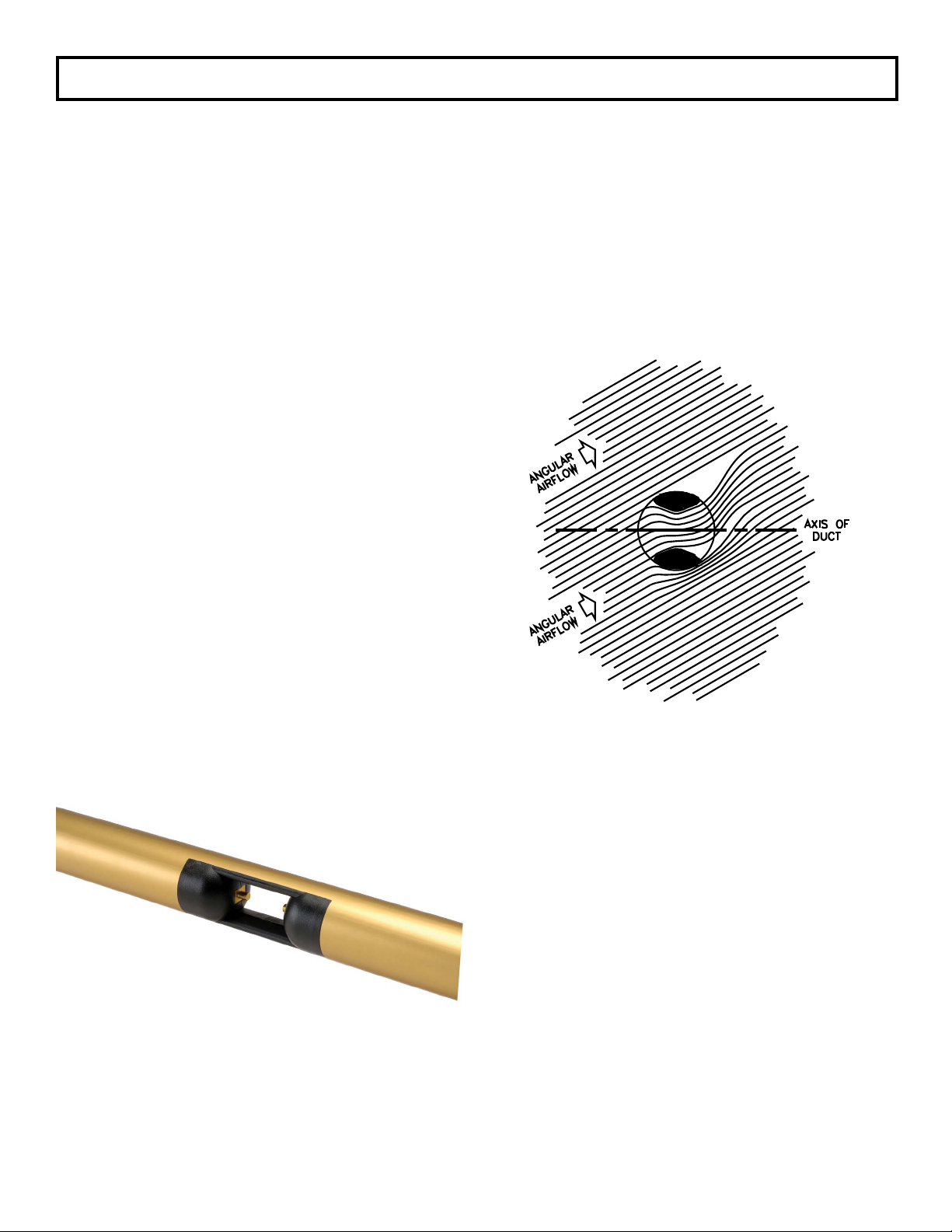
1.2 – THEORY OF OPERATION
The Vari-Green utilizes thermal dispersion technology
to measure airflow. As air moves across the surface of
an elevated temperature sensor, heat is transferred from
the sensor to the airflow in a mathematically defined
relationship between heat transfer rate and airflow
velocity.
Each Vari-Green sensing node utilizes a pair of precision
matched thermistors. One functions as a reference
sensor measuring the ambient air temperature at the
sensing node location, and the other thermistor is heated
to a preset temperature differential (∆T) above the
ambient air temperature. Airflow velocity is determined
using the measured ambient air temperature, the known
heat transfer characteristics of the heated thermistor,
and the power consumed to maintain the ∆T between
the two thermistors.
Using a combination of Computational Fluid Dynamics
(CFD) modeling and extensive full-scale wind tunnel
verification, the aerodynamically optimized cross section
of the sensing node aperture prevents error inducing
turbulence typical of sharp edged sensing tubes.
Using a combination of Computational Fluid Dynamics
(CFD) modeling and extensive full-scale wind tunnel
verification, the aerodynamically optimized cross section
of the sensing node aperture prevents error inducing
turbulence typical of sharp edged sensing tubes.
The aperture’s injection molded shape has been
engineered to minimize the angular flow effects
naturally present in any duct. The flared aperture
captures a representative sample of the ducted
airflow, while the contoured leading edges prevent the
creation of vortices. The center cross section of the
aperture functions in the same manner as a venturi. It
stabilizes and flattens the velocity profile at the point of
measurement ensuring the airflow maintains full contact
with the sensing thermistors. The flow conditioning
characteristic of the aperture compensates for turbulent
airflow with pitch and/or yaw angles up to ±30 degrees
and produces an accuracy of ±2% of reading for each
Vari-Green sensor.
4
Page 5

2 – PERFORMANCE SPECIFICATIONS
2.1 – ACCURACY
Sensor Accuracy.
Velocity: ±2% of Reading
Temperature: ±0.1ºF
Overall System Accuracy.
Flow: ±2-3% of Actual Flow
Temperature: ±0.1ºF of Air Temperature
2.2 – RANGE
Velocity Calibration Range.
Low Range (0 to 5,000 FPM)
High Range (0 to 10,000 FPM)
Custom Range (consult Factory)
2.3 – PROBE ASSEMBLY
Mounting.
4 in. x 4 in. aluminum plate with four 0.25 in. holes for
fasteners and neoprene gasket.
Length.
8 in. up to 120 in.
Sensors Per Probe.
Maximum of 16
Connection.
Probe to Probe via RJ-45 cable for signal and power.
Probe to Transmitter via shielded cable with RJ-45
connection. 10 foot length standard with optional 50
foot and 100 foot lengths.
Temperature Limits.
–20ºF to 180ºF Storage
–20ºF to 140ºF Operating
Humidity Limits.
0 to 95% RH, non-condensing.
2.4 – TRANSMITTER
Display.
3 line, backlit graphical display. Flow on Line 1 is
double height and width for improved visibility. Lines
2 and 3 are standard size and are user selectable.
Output.
Dual analog outputs (0-5VDC, 0-10VDC, 4-20mA)
user selectable and configurable.
Configuration.
Via cover mounted membrane keypad
Filter.
Analog outputs filtered via user selectable digital low
pass filter.
Temperature Limits.
–20ºF to 180ºF Storage
–20ºF to 140ºF Operating
Humidity Limits.
0 to 95% RH, non-condensing
2.5 – POWER
Power Supply.
24VAC or 24VDC.
Power Consumption.
16 to 90VA dependent on number of sensor nodes (1 to
32 maximum)
Circuit Protection.
Power input is isolated, fused, and reverse polarity
protected. Earth Ground must be connected to the
terminal labeled "G".
3 – FEATURES
3.1 – OPERATOR MENU
The microprocessor program contains a Operator menu
system for selecting parameters.
Four pushbuttons UP, DN, ENT, and ESC allow the
operator access to the menu for setting configuration
modes and values. Refer to the Configuration
Programming (Section 5.6) instructions for operation
details.
Also contained in the Operator menu is an output
calibration feature. The calibration method is completely
digital and contains no analog potentiometer
adjustments which are susceptible to drift. Non-volatile
memory is used for storing all setup parameters and
calibration values, and will remain unchanged after set,
even when power to the unit is off.
3.2 – DATA DISPLAY
The Vari-Green Thermal Air Flow Transmitter utilizes a
high visibility backlit graphical LCD. 3/4" x 2-1/2" display
with three lines of process data, selectable for U.S. or
S.I. units. Also used for configuration interface.
3.3 – LARGE OPERATION RANGE
The Vari-Green Thermal Air Flow System can maintain
accurate and linear output of flows from 0 to 5,000 FPM
(Low Range) and 0 to 10,000 FPM (High Range). Consult
factory for custom range.
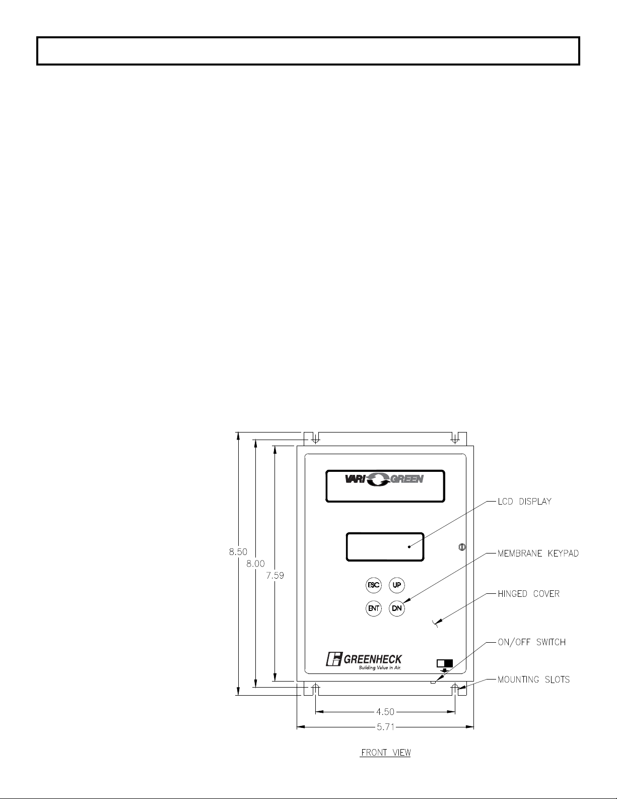
3.4 – ENCLOSURE
The Vari-Green Thermal Air Flow Transmitter is housed
in an aluminum NEMA 1 enclosure with hinged front
cover for access to power and signal terminals for field
connection.
3.5 – MULTIPLE OPERATING POWER
SELECTIONS
The Vari-Green Thermal Air Flow Transmitter can be
powered by either 24VAC or 24VDC.
5
Page 6
4 – INSTALLATION
4.1 – RECEIVING AND INSPECTION
• Carefully remove the Vari-Green Probe(s) or Station,
and Transmitter from the shipping container and
inspect for any damage. If any damage has occurred
in transit, contact freight carrier.
• Review the Factory Set-Up Information Sheet provided
separately and verify the W.O. # and Serial # match
those on the Vari-Green. Verify that the configuration
recorded on the Factory Set-Up Information Sheet
is correct for your application. If not, contact the
Greenheck dampers at 1-800-717-6540 for further
guidance.
Note: The Vari-Green has been configured to customer
provided parameters (see "Factory Setup Information
Sheet" provided separately), and requires no field
calibration/verification prior to installation.
4.2 – LOCATION
• The standard version of the Vari-Green Transmitter is
a NEMA 1 enclosure suitable for most clean indoor
locations. If additional protection is required, mount
the Transmitter in an enclosure with adequate NEMA
rating.
• The ambient temperature of the selected mounting
location must be between -20ºF to 140ºF.
Consideration should be given to units exposed to
direct sunlight.
• The selected mounting location should be rigid and
free of vibration.
4.3 – MOUNTING
Probes. See separate Installation Instructions for the
installation/mounting of Vari-Green Probes and Stations.
Transmitter. This section may be skipped if the
Transmitter was ordered factory mounted to the station.
– Tools Required: electric drill; #25 (0.1495”) bit;
screwdriver or nutdriver; and four #8-32 self-tapping
machine screws.
– The Vari-Green can be mounted in any position
provided it is secured using all four mounting holes.
– Reasonable consideration should be given to
clearances for electrical connections.
– Once a suitable location is found, use the unit as a
template to mark the centers of the four mounting
holes.
– Drill four pilot holes at the marked locations. With the
unit in position, install the four #8-32 screws.
®
Thermal Air Flow Transmitter
®
OFF ON
Figure 4.1
6
Page 7
4.4 – PROCESS CONNECTIONS
See separate Installation Instructions provided with the Vari-Green Probes or Station for information on connecting
cables from the Probes or Station to the Transmitter.
If the Vari-Green have been purchased with a factory mounted transmitter, all connector cabling has already been
installed.
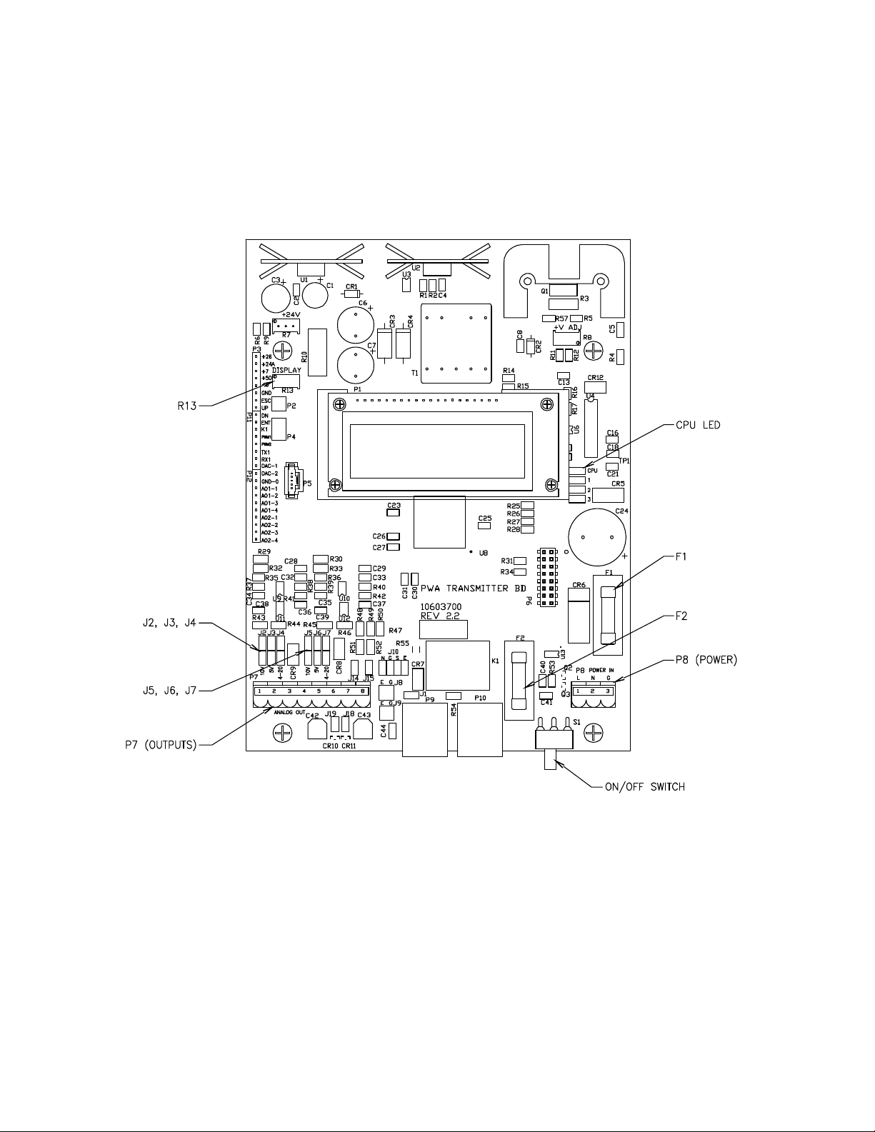
4.5 – POWER/SIGNAL CONNECTIONS
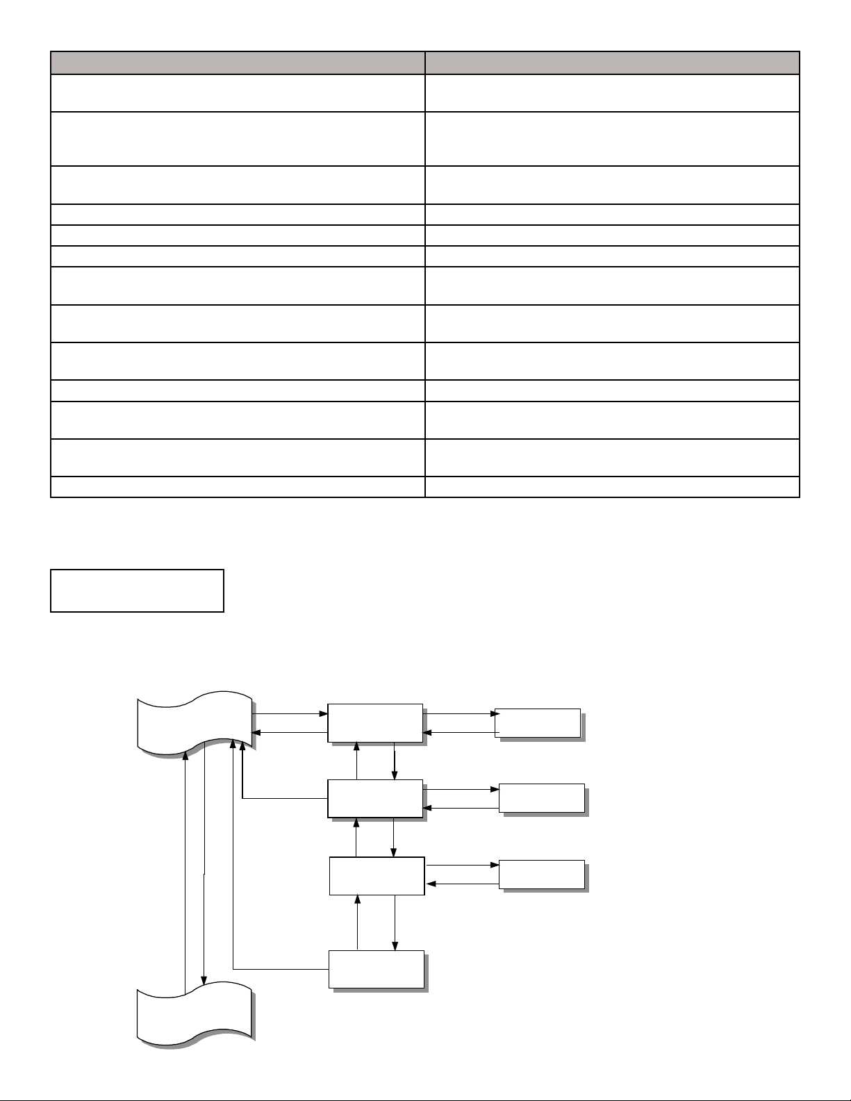
Power wiring is done at terminal strip P8, and signal wiring is done at terminal strip P7. Both P7 and P8 are located
in the lower portion of the transmitter and are accessible by opening the front cover. See Figure 4.2 for location of
P7 and P8. Two conduit openings are provided in the bottom of the transmitter for the power and signal wiring.
Figure 4.2
WIRING.
It is recommended that power wiring be 14 awg to 18
awg, and signal wiring should be 14 awg to 22 awg.
14 awg is the maximum wire gauge that the terminals
can accommodate. No more than two wires should be
connected to any one terminal. To aid in the wiring of
both power and signal wires, P7 and P8 are removable
by pulling the terminal strip straight up and off the circuit
board. Once wiring has been completed, replace the
terminal strip by aligning with receptacle and pressing
firmly.
POWER 24 VAC/DC (Terminals L, N and G, P8).
Power required by the Vari-Green must be connected
to the two terminals labeled L(+) and N(–). Earth ground
must be connected to the terminal labeled G. Power
Supply must be 20-28VAC or 20-40VDC.
OUTPUT #1 (Terminals 1(+) and 2(-), P7).
This output represents the measured airflow and is
sourced (powered) by the Vari-Green. Output can be
configured for 0-5VDC, 0-10VDC, or 4-20mADC. Review
Factory Set-Up Information Sheet for your configuration.
If output is to be 0-5VDC: Position both jumpers on
J3. See Figure 4.2.
If output is to be 0-10VDC: Position both jumpers on
J2. See Figure 4.2.
If output is to be 4-20mADC: Position both jumpers on
J4. See Figure 4.2.
In addition to positioning the jumpers for the desired
output type, the corresponding output type must be
selected in the Operator Menu (see Section 5.12).
7
Page 8

4.5 – POWER/SIGNAL CONNECTIONS (con’t)
OUTPUT #2 (Terminals 3(+) and 4(-), P7).
This output can represent the measured flow (0 - Design
Full Range) or temperature (0 to 140ºF / -18 to 60ºC) and
is sourced (powered) by the Vari-Green. Output can be
configured for 0-5VDC, 0-10VDC, or 4-20mADC. Review
Factory Set-Up Information Sheet for your configuration.
If output is to be 0-5VDC: Position both jumpers on
J6. See Figure 4.2.
If output is to be 0-10VDC: Position both jumpers on
J5. See Figure 4.2.
If output is to be 4-20mADC: Position both jumpers on
J7. See Figure 4.2.
In addition to positioning the jumpers for the desired
output type, the corresponding output type must be
selected in the Operator Menu (see Section 5.12).
SNVT SNVT Index Measurement Units Type Category Type Size
SNVT_flow_f 53 Flow Volume Liters/Sec Floating Point 4 bytes
SNVT_temp_p 105 Temperature °C x 100 Signed Long 2 bytes
For BACnet, connections are as follows:
Terminal 5 – Net A or Net +
Terminal 6 – Net B or Net Terminal 7 – Network Ground
For BACnet objects, see Appendix A.
Set the S1 Termination switches on the BACnet module as follows:
Network Connection (Terminals 5, 6 & 7, P7).
This serial output is available with optional LonWorks or
BACnet (Version 1.5X only) communication.
For LonWorks, connections are as follows:
Terminal 5 – LonWorks B
Terminal 6 – LonWorks A
Terminal 7 – Ground
Two output variables are provided, flow volume and
temperature.
S1 Switch Position
Termination Type 1 2 3
No Termination OFF OFF OFF
End of Line ON OFF OFF
Fail-safe Bias ON ON ON
Note: The Fail-safe Bias termination includes End of Line termination.
4.6 – DISPLAY CONTRAST ADJUSTMENT
To compensate for different ambient lighting conditions and viewing angles, the Vari-Green display's contrast can
be adjusted for optimum visibility. Contrast is adjusted using potentiometer R13. Turn R13 clockwise to increase
contrast (darken characters relative to background) or counterclockwise to decrease contrast.
8
Page 9
5 – OPERATION
5.1 – INTRODUCTION
The Vari-Green has been configured at the factory to
customer specified parameters. Review this information
and verify that the Vari-Green set-up is correct for
your application. If any problems or discrepancies are
detected, contact Greenheck Dampers at 1-800-7176540 prior to proceeding.
5.2 – START-UP
1. After Installation has been verified in accordance with
Section 4, turn power switch located at the lower front
side to the ON position (see Figure 4.1).
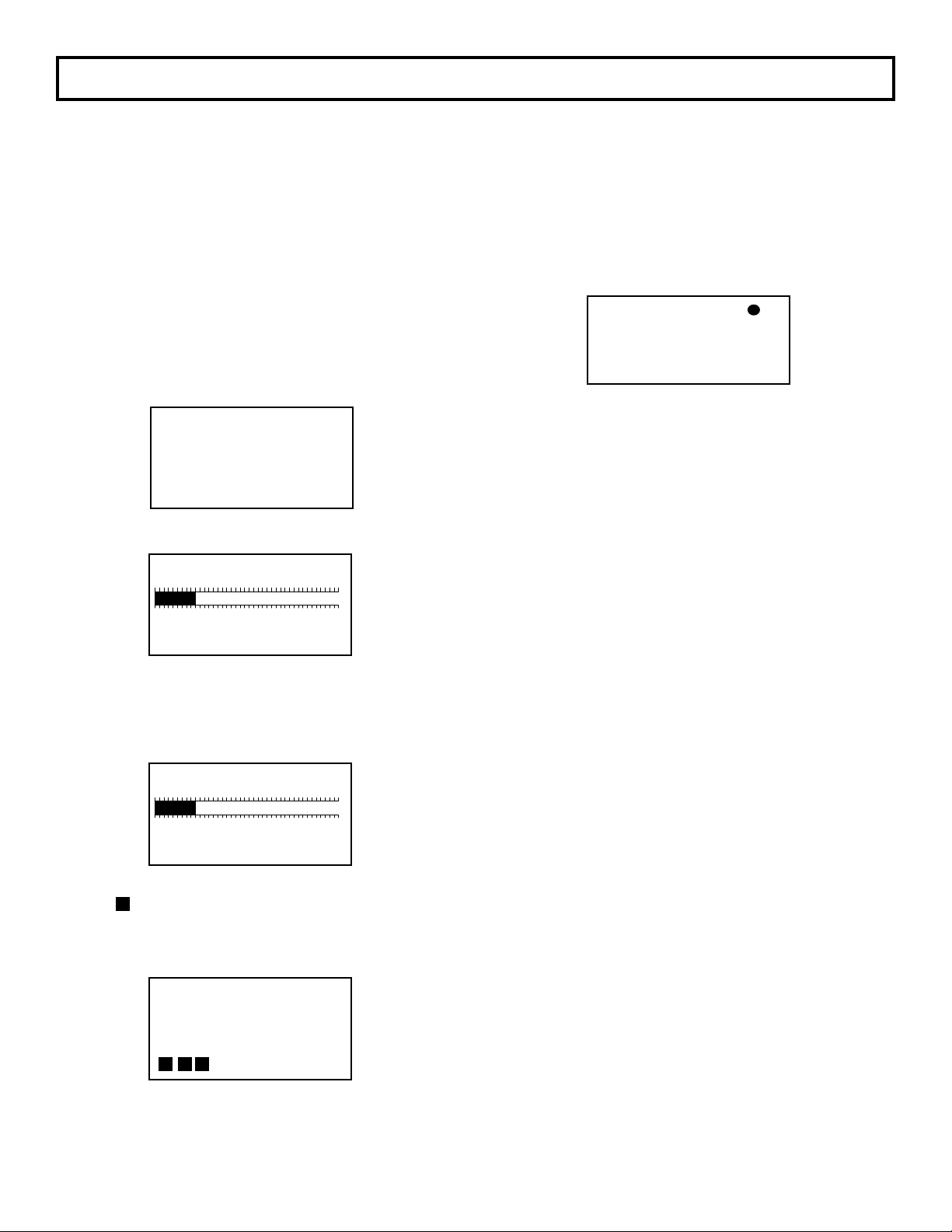
2. Display will briefly indicate:
Followed by:
The number of active sensors will be represented by
Vari-Green
- - - - - - - - - - - - - - - - - - Thanks for Choosing
Greenheck
the bar graph and listed below. There are 8 active
sensors in this example.
1 8 16 24 32
Sensors Found: 8
Total Sensors: 8
After 5 seconds, display will indicate:
The number of enabled sensors will be represented
by the bar graph and listed below. There are 8 active
sensors in this example.
1 8 16 24 32
After 20 seconds, the display will return to Normal
display mode, and the dot in the upper right of the
display indicating CPU Activated will blink rapidly (4
times per second). This is Normal operation mode
and no further user interface is required. If, however,
user would like to verify configuration or change user
selectable parameters, continue to Section 5.4 entitled
“CONFIGURATION”.
0 ACFM
VELO 0 AFPM
TEMP 68.0°F
Normal display mode
* Dot flashes 4 times a second, indicating that
CPU is active. If ALERT flashes instead of Dot, see
section for Diagnostics.
*
5.3 - NORMAL OPERATION
Under Normal operation, the Vari-Green transmitter will
continuously display flow and velocity, or temperature.
5.4 - CONFIGURATION
The Vari-Green onboard microprocessor controls
Configuration: Operating parameter selection; input/
output activation and scaling, and display scaling.
The customer can verify configuration and change
certain parameters (within defined ranges) by
entering the Vari-Green Configuration mode. This is
accomplished using the four membrane pushbuttons
located on the Vari-Green cover. See Figure 4.1 for
location of pushbuttons.
Enabled Sensors: 8
Total Sensors: 8
After 5 seconds, display will indicate:
with the progressing from left to right.
Vari-Green
- - - - - - - - - - - - - - - - - - - Sensor Warming Up
®
9
Page 10

5.5 – PUSHBUTTON DEFINITION
The four pushbuttons used to interface with the Vari-Green are as follows: UP DN ENT ESC
In addition to use during Configuration programming, pushbuttons can be used for certain functions when in the
Normal operation mode. The following list describes the pushbutton function when in the Normal operation mode
and in the User Setup (programming).
When in Normal Operation Mode.
ENT then ESC then UP then ENT Activates the Operator menu.
ENT then ESC then DN then ENT Activates the Supervisor menu.
ENT Activates Password selection menu.
ENT then UP then DN then ENT Displays ID, ESID, and WO#. Press UP and software version and maximum
velocity will be displayed. Press ESC and the display will go back to the
Normal operation mode.
When in User Setup.
UP or DN Use to scroll to the desired Main Menu item.
Use to scroll to the value or mode within a parameter.
ENT Enters user into specific selection sub-menu from Main Menu Selection.
Displays current setting of selected Parameter. Enters the selected value or
setting into memory.
ESC Use as an escape key to exit back to Main Menu selection to avoid scrolling
to Return to MAIN MENU
The following pushbutton combinations can be used to more quickly set user selected values (i.e. Process Min and
Max Values, etc.).
UP* + ESC Increases the second column digit.
DN* + ESC Decreases the second column digit.
UP* + DN Increases the third column digit. XXXXX
DN* + UP Decreases the third column digit.
UP* + ESC + DN Increases the fourth column digit.
DN* + ESC + UP Decreases the fourth column digit.
*Must be pressed and held before other button(s) are pressed.
Note: Pushbuttons are momentary type and should be quickly pressed and released to initiate desired change,
unless otherwise instructed to press and hold.
2nd Column
3rd Column
4th Column
5.6 – CONFIGURATION PROGRAMMING
1. With power ON and initialization complete (see Section 5.2), press ENT then ESC then UP then ENT to activate
the Operator menu. The display will indicate:
ENTER PASSWORD FOR
OPERATOR MENU
XXXX
Note: If Operator Menu password has been bypassed (see Section 5.7), the display will indicate as shown in Step 3
below.
2. Using UP and ENT, scroll to the numeric password for the Operator Menu. From the Factory, password is set for
1,111.
3. Once password is displayed, press ENT and display will indicate:
4. Press ENT and display will indicate:
By using UP and DN, the user can scroll through the following selections:
10
OPERATOR MENU
OPERATOR PASSWORD
Page 11
Main Menu Selection Description
between VELOCITY,
between VELOCITY,
Operator Password Selection Allows for the selection of password for the Operator Menu, and the
bypassing of the password
Flow Configuration Allows for the configuration of process variable such as: Duct size
and shape, process type, process maximum/units, and percent
lockdown
Display Configuration Allows the selection of parameter to be displayed on Lines 2 & 3,
and display filter
Output 2 Parameter Selection Allows the selection Output 2 parameter
Low Pass Filter Selection Selects amount of filtering applied to the output and to the display
Output Signal Type Selection Allows the selection of signal type for Output 1 and 2
Transmitter Output Calibration Allows for the zeroing and spanning of transmitter analog Outputs
1 and 2
K-factor Configuration Turns K-factor ON or OFF and allows for the calculation or selection
of exponent and gain values
Menu Inactivity Timeout Selection Allows for the selection a time after which the unit returns to
normal operation if no activity in the Operator Menu
Network Configuration Turns the Network ON or OFF, and allows BACnet configuration
Flow Alarm Configuration
(available only with BACnet Network Option)
Temperature Alarm Configuration
(available only with BACnet Network Option)
Operator Menu Exit Returns display to Normal operation
Turns each alarm ON or OFF, select High and Low Setpoints,
Deadband selection and Alarm Delay
Turns each alarm ON or OFF, select High and Low Setpoints,
Deadband selection, and Alarm Delay
5. Once the desired selection is displayed, press ENT to enter its sub-menu.
Once the desired Selection is displayed, its sub-menu can be entered by pressing ENT.
At any time while in the Operator Menu, User can return to Normal operation mode by pressing ESC or scrolling to:
OPERATOR MENU
and pressing ENT.
EXIT
To better understand the process of Configuration Programming, arrows with pushbutton designation have been
included on the following flow chart of Display Configuration. This will aid in the navigation of the Configuration
Programming Process.
Operator Menu
Display Configuration
DN
UP
ENT
ESC
ESC
ENT or ESC
Display Filter
Selection
DN
Line 2 Parameter
Selection
DN
Line 3 Parameter
Selection
DN
Return to
MAIN MENU
UP
UP
UP
ENT
ENT or ESC
ENT
ENT or ESC
ENT
ENT or ESC
Line 2 Parameter
Line 2 Parameter
TEMPERATURE
Display Filter
0 (None)
VELOCITY
UP or DN will scroll
between 0 and 5
UP or DN wil scroll
TEMPERATURE, &
CUSTOM TEXT
UP or DN wil scroll
TEMPERATURE, &
CUSTOM TEXT
Output 2 Parameter
Selection
This example of navigation is similar for all Operator Menu selections.
11
Page 12

Note: All selections that are available for further configuration programming will have an “arrow” symbol
displayed in the right side of the display field. Those that are not available for further configuration
programming will not have the “arrow” symbol displayed and will display Not Installed beneath the selection
description. Example:
Network option is
not installed
The remainder of this Section details steps to verify or change Configuration Programming of all Operator Menu
Selections.
5.7 – OPERATOR PASSWORD SELECTION
Allows the selection of an Operator Menu password and the option of bypassing the password.
Operator Menu
- OPERATOR MENU EXT
Operator Password Select
- Flow Configuration
Password Menu
- Password Selection
- Bypass Password? Selection
- Return to MAIN MENU
Default selection shown
Password
1, 111
Bypass Password?
NO
Return to
MAIN MENU
Available selections
0 to 9,999
NO or YES
Note: The Operator Password menu can be accessed directly following start-up (power ON) by pressing:
UP then DN then UP then ESC.
1. While in Operator Menu, use UP or DN to scroll to:
Operator Password
Selection
2. Press ENT to enter Operator password menu. Display will indicate:
Password
Selection
3. Press ENT and display will indicate current password.
Note: From the Factory, password is set for 1,111
4. Use UP or DN to change password. Once desired password is displayed, press ENT. New password will be
stored in memory and display will return to previous menu (see Step 2).
Caution: If password is changed, write it down, and retain in case it is forgotten.
Note: If user desires not to change password and return to password menu, press ESC. Unit will remain
programmed as it was originally.
5. Use UP to select Bypass Password if desired.
6. Follow Steps 3 and 4 to make changes.
CAUTION: If YES is selected, this will eliminate the need to enter any password when accessing the Operator Menu.
7. To return to Main Menu, select Return to MAIN MENU in the Operator Password Selection menu, and press ENT.
12
Page 13

5.8 – FLOW CONFIGURATION
Operator Menu
Dimensional Units
U.S.
Temperature Units
°F
Duct Shape
RECTANGULAR
Duct Height
XX.XX in.
Duct Width
XX.XX in.
Duct Diameter
XX.XX in.
Duct Area
XX.XX Sq. Ft.
Actual or Standard
ACTUAL
Maximum Full Range is based
This Operator Menu selection is where all application specific data is entered to configure the Vari-Green for a
unique application. Typical data includes: Units of Measure, Duct Type and Size, Flow Type, Units and Conditions,
and Output Lockdown.
Note: The factory has entered data in this section based on customer supplied information. Data can be reviewed
and verified by scrolling through the individual menu items or reviewing the Factory Set-Up Information
sheet provided separately. Review this information BEFORE making any changes as it can have a
significant effect on the operation of the Vari-Green.
Flow Configuration MenuOperator Menu
Default slection shown
- Operator Password Selection
Flow Configuration
- Display Configuration
- Dimensional Units Selection
- Temperature Units Selection
- Duct Shape Selection
- Duct Height Selection ¹
- Duct Width Selection ¹
- Duct Diameter Selection ²
- Duct Area Selection ³
- Actual or Standard Selection
- Site Elevation Selection
- Volume Units Selection
- Design Full Range Selection
- Output Lockdown Selection
- Return to MAIN MENU
¹ Available only if RECT ANGULAR or OVAL is
selected as Shape
² Available only if ROUND is selected as Shape.
³ Available only if OTHER is selected as Shape.
U.S or METRIC
°F or °C
RECTANGULAR, ROUND,
OVAL, FAN INLET-SINGLE,
FAN INLET-DOUBLE, or
OTHER
0.00 to 300.00 in.
0 to 10,000 mm
0.00 to 300.00 in.
0 to 10,000 mm
0.00 to 300.00 in.
0 to 10,000 mm
0.00 to 325.00 Sq.Ft.
0 to 35,500 Sq. M.
Actual or
Standard
Design Full Range
XX,XXX ACFM
1. While in Operator Menu, use UP or DN to scroll to:
2. Press ENT to enter Flow Configuration menu. Display will indicate:
3. Press ENT and display will indicate current setting of Units (U.S. or METRIC).
Maximum Full Range
XX,XXX ACFM
Output Lockdown
Site Elevation
0 Feet
Volume Units
ACFM
4
200 AFPM
Return to
MAIN MENU
0 to 15,000 Feet
0 to 4,572 M.
See UNITS list for
available
selections
Design value
adjustable up to
maximum value.
0 to 5000 AFPM
4
on the duct area.
Flow
Configuration
Dimensional Units
Selection
13
Page 14

4. Use UP or DN to change setting. Once desired setting is displayed, press ENT, new setting will be stored in
memory and display will return to Flow Configuration menu as in Step 2.
Note: If user desires not to change the setting and return to the Flow Configuration menu, press ESC. Unit will
remain programmed as it was originally.
5. Use UP or DN to select remaining parameters to be changed within the Flow Configuration menu.
6. Follow Step 4 to make any changes to parameters.
See the following Units List for the available selections for the appropriate Flow Type.
Units List for Volume
Unit of Measurement Display
Actual cubic feet per minute ACFM
Actual cubic feet per hour ACFH
Actual liters per second Al/s
Actual liters per minute Al/m
Actual cubic meters per hour Am3/h
Standard cubic feet per minute SCFM
Standard cubic feet per hour SCFH
Standard liters per second Sl/s
Standard liters per minute Sl/m
Standard cubic meters per hour Sm3/h
7. To return to the Main Menu, select Return to MAIN MENU in the Flow Configuration menu and press ENT.
5.9 – DISPLAY CONFIGURATION
Allows selection of display parameter for lines 2 and 3. Also, the level of filtering, 0 through 5 (5 is the maximum) can
be selected by User.
Operator Menu
- Flow Configuration
Display Configuration
- Output 2 Parameter Selection
Display Configuration Menu
- Display Filter Selection
- Line 2 Parameter Selection
- Line 2 Custom Text Selection
- Line 3 Parameter Selection
- Line 3 Custom Text Selection
- Return to MAIN MENU
1
Available only if Parameter is
CUSTOM TEXT.
Default selection shown
Display Filter
1
1
0 (None)
Line 2 Parameter
TEMPERATURE
Line 2 Custom Text
Line 3 Parameter
VELOCITY
Available selections
0 (None) to
5 (Maximum)
TEMPERATURE,
CUSTOM TEXT,
or VELOCITY
See ASCII
Character Chart for
Selection
TEMPERATURE,
CUSTOM TEXT,
or VELOCITY
14
Line 3 Custom Text
Return to
MAIN MENU
See ASCII
Character Chart for
Selection
Page 15

5.9 – DISPLAY CONFIGURATION (con’t)
1. While in Operator Menu, use UP or DN to scroll to:
Display
Configuration
2. Press ENT to enter Display Configuration menu. Display will indicate:
Display Filter
Selection
3. Press ENT and display will indicate current setting of the filter [0 (None), 1 (Minimum), 2, 3, 4, or 5 (Maximum)].
4. Use UP or DN to change setting. Once desired setting is displayed, press ENT, new setting will be stored in
memory and display will return to Display Configuration menu as in Step 2.
Note: If user desires not to change the setting and return to the Display Configuration menu, press ESC. Unit will
remain programmed as it was originally.
5. Use UP and display will indicate:
Line 2 Parameter
Selection
6. Press ENT and display will indicate current parameter selected to display on Line 2 (VELOCITY, TEMPERATURE,
or CUSTOM TEXT).
7. Use UP or DN to scroll to desired parameter. Press ENT, and parameter will be stored in memory and display will
indicate as in Step 5.
Note: If user desires not to change the setting and return to the Setup menu, press ESC. Unit will remain
programmed as it was originally.
8. If CUSTOM TEXT was selected and ENT pressed in Step 7, proceed to Step 13. For other parameters, continue
with Step 9.
9. Press UP and display will indicate:
Line 3 Parameter
Selection
10. Repeat Steps 6 through 8 for Line 3. The only differences being the change of Line # in the display.
11. After Line 3 has been set, Step 9 will yield a display:
Return to
MAIN MENU
12. Press ENT to return to Main Menu.
13. If Custom Text was selected and ENT pressed in Step 7 (or for Line 3), press UP and display will indicate:
Line 2 Custom Text
Selection
14. Press ENT and display will indicate:
Line 2 Custom Text
Cursor indicates position to be set.
There are 20 positions available to
hold custom text.
15. Use UP or DN to scroll through available characters (see ASCII Chart at the end of this Section for available
characters).
16. When desired character is displayed, press ENT, character will be stored and cursor will advance one position to
the right.
17. Repeat Steps 15 and 16 for all 20 positions. When position 20 is entered, user will be exited back to display as in
Step 13.
15
Page 16

In “Set Custom Text” mode, the pushbuttons can be used in the following combinations to facilitate programming.
ESC + UP Moves position cursor to the right, one position at a time.
ESC + DN Moves position cursor to the left, one position at a time.
ESC + ENT Exits “Set Custom Text”. Does not enter any changes to the display since the last time ENT was
pressed.
UP + DN Jumps up five characters at a time, to the desired character.
DN + UP Jumps down five characters at a time, to the desired character.
ASCII Character Chart
! * 3 < E N W ` i r {
+ 4 = F O X a j s l
″
#
$ - 6 ? H Q Z c l u
% . 7 @ I R [ d m v
& / 8 A J S
'
( 1 : C L U
5 > G P Y b k t }
'
e n w
¥
0 9 B K T ] f o x
g p y
^
↑
↓
) 2 ; D M V - h q z
5.10 – Output 2 Parameter Selection
Allows the selection of which process variables Output 2 represents.
Process variables available for output are: Flow, Temperature, or None.
If Flow is selected, output will represent 0 to Design Full Range (see Section 5.8).
Operator Menu
- Display Configuration
Output 2 Parameter Select
- Low Pass Filter Selection
Default selection shown
Output 2 Parameter
TEMPERATURE
Available selections
FLOW, NONE
TEMPERATURE
If Temperature is selected, output will represent 0º to 140ºF (-18ºC to 60ºC).
1. While in Operator Menu, use UP or DN to scroll to:
Line 3 Parameter
Selection
2. Press ENT and display will indicate current setting of Output #2 (Flow, Temperature or None).
3. Use UP or DN to change setting. Once desired setting is displayed, press ENT. New setting will be stored in
memory and display will return as in Step 1.
Note: If user desires not to change the setting and return to Output 2 Parameter menu, press ESC. Unit will
remain programmed as it was originally.
16
Page 17

5.11 – Low Pass Filter
Allows selection of level of Process filtering applied to the output. Levels are 0 to 10, with 0 representing no filtering
and 10 representing maximum filtering. Display Filter is an additional filter selection applied only to the display.
This filtering affects all subsequent outputs and displays.
Operator Menu
- Output 2 Parameter Selection
Low Pass Filter Selection
- Output Signal Type Selection
Default selection shown
Low Pass Filter
1 (Minimum)
Available selections
0 (None) to
10 (Maximum)
1. While in Operator Menu, use UP or DN to scroll to:
Low Pass Filter
Selection
2. Press ENT and display will indicate current setting of Process filter; (0 (none) to 10
(maximum).
3. Use UP or DN to change setting. Once desired setting is displayed, press ENT. New setting will be stored in
memory and display will return as in Step 1.
Note: If user desires not to change the setting and return to Output 2 Parameter menu, press ESC. Unit will
remain programmed as it was originally.
5.12 – Output Signal Type Selection
User can select signal type for Output 1 and 2.
The output types selected below must correspond to the types selected via jumpers J3 through J7 (see Section 4.5).
Operator Menu
- Low Pass Filter Selection
Output Signal Type Select
- Transmitter Output Calibration
Output Signal Menu
- Output 1 Signal Type Selection
- Output 2 Signal Type Selection
- Return to MAIN MENU
1. While in Main Menu, use UP or DN to scroll to:
Default selection shown
Output 1 Signal Type
4-20 mA
Output 2 Signal Type
4-20 mA
Return to
MAIN MENU
Available selections
4-20 mA,
0-10 Vdc, 0-5 Vdc
4-20 mA,
0-10 Vdc, 0-5 Vdc
Output Signal Type
Selection
2. Press ENT to enter Output Signal Type menu. Display will indicate:
Output Signal Type
Selection
3. Press ENT and display will indicate current signal type (4-20mA).
4. Use UP or DN to change signal type. Once desired signal type is displayed, press ENT. New signal type will be
stored in memory and display will return to Output Signal Type Selection menu as in Step 2.
Note: If user desired not to change the signal type and return to Output Signal Type Selection menu, press ESC.
Unit will remain programmed as it was originally.
5. Use UP or DN to select remaining parameters to be changed.
6. Follow Step 4 to make any changes to parameters.
7. To return to Main Menu, select Return to MAIN MENU in Output Signal Type Selection menu and press ENT.
17
Page 18

5.13 – Transmitter Output Calibration
Allows for the calibration of the Vari-Green analog outputs.
Operator Menu
- Output Signal type Selection
Transmitter Output Calib.
- K-Factor Configuration
Output Calibration Menu
- Output 1 Zero Selection
- Output 1 Span Selection
- Output 2 Zero Selection
- Output 2 Span Selection
- Return to MAIN MENU
See Calibration
Instructions
Note: Unit is supplied Factory calibrated.
This section can be accomplished with the Vari-Green mounted in its operating location or at a test bench in a calibration
lab.
Required Equipment.
1. Digital Multimeter
Preparation.
1. Turn Power switch OFF on the Vari-Green (see Figure 4.1).
2. Open cover of the Vari-Green.
3. Remove all wires connected to terminals 1 through 4 (see Figure 4.2).
4. Turn Power switch ON.
1. While in Operator Menu, use UP or DN to scroll to:
Transmitter Output
Calibration
2. Press ENT to enter Display Configuration menu. Display will indicate:
Output 1 Zero
Selection
Type is 4-20 mA
3. Press ENT. Display will indicate:
Output 1 Zero
Perform Calibration
4. Connect a DMM set for type and scale of Transmitter Output 1 (as indicated on display)
Type is 4-20 mA
across terminals 1 and 2 on the Vari-Green (see Figure 4.2).
Note: If the output is 4-20mA, a load resistance should be in series with the DMM. This can be accomplished by
connecting the actual process load or a resistor of similar value to the actual process load.
DMM should be reading a minimum value; 0.00 ± 0.01 volts or 4.00 ± 0.01mA.
5. If DMM is reading out of tolerance, use UP or DN to adjust the Vari-Green output for an acceptable DMM reading.
Depending on DMM’s selected range, the UP or DN button may need to be pressed and held for a period of time
before any change occurs in the DMM’s display. To speed up changes in output, pushbutton combinations can be
used. The following chart lists these combinations along with the associated change in output type.
18
Page 19

Pushbutton
Combination
UP only +0.001mA +0.3mV +0.6mV
DN only -0.001mA -0.3mV -0.6mV
UP* + ESC +0.01mA +0.003V +0.006V
DN* + ESC -0.01mA -0.003V -0.006V
UP* + DN +0.1 mA +0.03V +0.06V
DN* + UP -0.1mA -0.03V -0.06V
UP* + ESC* and DN +1.0mA +0.3V +0.6V
DN* + ESC* and UP -1.0mA -0.3V -0.6V
*Must be pressed and held before other button(s) are pressed.
6. Once an acceptable zero reading is obtained, press ENT and then UP and display will indicate:
4-20mA
Output Type
0-5VDC
0-10VDC
Output 1 Span
Selection
Type is 4-20 mA
7. Press ENT. Display will indicate:
8. With DMM still connected as in Step 4, reading should be at maximum value; 10.00 ± 0.01 volts, 5.00 ± 0.01 volts,
or 20.00 ± 0.1mA.
9. If DMM is reading out of tolerance, use UP or DN to adjust the Vari-Green’s output for an acceptable DMM
reading.
10. Once an acceptable span reading is obtained, press ENT and then UP and display will indicate:
11. Repeat Steps 3 through 10 for Transmitter Output 2. For Transmitter Output 2, connect DMM across terminals 3
and 4.
12. Press UP and display indicates:
Output 1 Span
Selection
Type is 4-20 mA
Output 1 Zero
Selection
Type is 4-20 mA
Return to
MAIN MENU
19
Page 20

5.14 – K-Factor Configuration
Operator Menu
K-Factor Off/On
OFF
Calculate K-Factor?
NO
Numbr of Data Points
One Point
Measured Point 1
1,000 ACFM
Measured Point 2
5,000 ACFM
Measured Point 3
9,000 ACFM
Reference Point 1
1,000 ACFM
Reference Point 2
5,000 ACFM
Caution
In the majority of applications, the use of a K-Factor is neither required nor desirable.
Before using the K-Factor feature, contact the factory (see Section 8) to review
the application and obtain assistance in determining the K-Factor exponent and gain values.
Turns K-factor function ON or OFF, calculate a K-Factor exponent and gain from measured data, or select a K-Factor
exponent value and K-Factor gain value.
Note: If K-Factor is ON, Process displays will have an asterisk (KFon) to the right of the flow value.
Flow Configuration MenuOperator Menu
Default slection shown
- Transmitter Output Calibration
K-Factor Configuration
- Menu Inactivity Timeout Select
- K - Factor Off/On Selection
- Calculate K-Factor? Selection
- Numbr of Data Points Selection
- Measured Point 1 Selection ¹
- Measured Point 2 Seleciton ¹
- Measured Point 3 Selection 1,²
- Reference Point 1 Selection
- Reference Point 2 Selection
- Reference Point 3 Selection
- Perform Calculation Selection
- K-Factor Exponent Selection
- K-Factor Gain Selection
- Return to MAIN MENU
¹ Available only if YES is selected in Calculate K-Factor?
² Depends on the number of Data Points selected
³ Available only if NO is selected in Calculate K-Factor?
1
,2
1
1,2
1,2
1
3
3
Reference Point 3
9,000 ACFM
EXPO: 1.0000
GAIN: 1.000
K-Factor Exponent
1.0000
K-Factor Gain
1.000
Return to
MAIN MENU
OFF or ON
NO or YES
One Point
Two Points
Three Points
Uses Process Units
& Format Selected
in Process Config.
Uses Process Units
& Format Selected
in Process Config.
Uses Process Units
& Format Selected
in Process Config.
Uses Process Units
& Format Selected
in Process Config.
Uses Process Units
& Format Selected
in Process Config.
Uses Process Units
& Format Selected
in Process Config.
Calulated from data
entered above
0.5000 to 2.0000*
0.0001 increments
0.000 to 32.750*
0.0001 increments
*Available Range depends on
operating span versus natural
span.
20
Page 21

5.14 – K-Factor Configuration (con’t)
1. While in Operator Menu, use UP or DN to scroll to:
K-Factor
Configuration
2. Press ENT to enter K-Factor Configuration menu. Display will indicate:
K-Factor Off/On
Selection
3. Press ENT and display will indicate current setting of K-Factor (OFF or ON).
4. Use UP or DN to change setting. Once desired setting is displayed, press ENT. New setting will be stored in
memory and display will return to K-Factor Configuration menu as in Step 2.
Note: If user desires not to change the setting and return to K-Factor Configuration menu, press ESC. Unit will
remain programmed as it was originally.
5. Use UP or DN to select remaining parameters to be changed.
6. Follow Step 4 to make any changes to parameters.
7. To return to Main Menu, select Return to MAIN MENU in parameter menu and press ENT.
5.15 – Menu Inactivity Timeout Selection
Allows user to select a time (minutes) after which the unit returns to Normal operation if no activity in the Operator Menu.
Operator Menu
- K-Factor Configuration
Menu Inactivity Timeout Select
- Network Selection
Output Calibration Menu
Menu Inactivity
2 Minutes
OFF to 30 minutes,
1 minute increments
1. While in Main Menu, use UP or DN to scroll to:
Menu Inactivity
Timeout Selection
2. Press ENT and display will indicate current timeout value (1 to 30 minutes or OFF).
3. Use UP or DN to change timeout value. Once desired value is displayed, press ENT. New setting will be stored in
memory and display will return to Main Menu.
Note: If user desires not to change the setting and return to Main Menu, press ESC. Unit will remain programmed
as it was originally.
21
Page 22

5.16 – Network Configuration
Allows user to turn network ON or OFF, and configure parameters based on Network type. BACnet available only with
version 1.5X.
Operator Menu
Network Configuration Menu
1
Default slection shown
- Menu Inactivity Timeout Select
Network Configuration
- Flow Alarm Configuration
- Network ON/OFF Selection
- BACnet Instance ID Selection
- BACnet Instance ID Selection
- BACnet MaxMasters Selection
- BACnet Baud RateSeleciton
- Return to MAIN MENU
¹ Available only with Network option
² Available only with BACnet
2
2
2
2
1. While in Main Menu, use UP or DN to scroll to:
2. Press ENT to enter Network Configuration menu. Display will indicate:
Network Off/On
OFF
BACnet Instance ID
0
BACnet Address
1
BACnet Max Masters
1
Bacnet Baud Rate
9600
Return to
MAIN MENU
OFF or ON
0 to 4,194,303
1 to 127
1 to 127
9600, 19200,
38400, or 76800
Network
Configuration
Network Off/On
Selection
3. Press ENT and display will indicate current setting of Network (OFF or ON).
4. Use UP or DN to change setting. Once desired setting is displayed, press ENT and new setting will be stored in
memory and display will return to Network Configuration menu as in Step 2.
Note: If user desires not to change the setting and return to Network Configuration menu, press ESC. Unit will
remain programmed as it was originally.
5. Use UP or DN to select remaining parameters to be changed.
6. Follow Step 4 to make any changes to parameters.
7. To return to Main Menu, select Return to MAIN MENU in Network Configuration menu and press ENT.
5.17 – Flow Alarm Configuration
Available only with BACnet Network option.
User can turn each Alarm ON or OFF, select type of alarm and set the following values:
Alarm 1 Setpoint (this is Low, Low1, or High1 depending on Alarm Type): Selected value of flow below (for Low and
Low1) or above (for High 1) which an alarm condition will exist.
Alarm 2 Setpoint (this is High, Low2, or High2, depending on Alarm Type): Selected value of flow below (for Low2) or
above (for High and High2) which an alarm condition will exist.
Alarm Deadband: Value that transmitter signal has to reach above (for Low, Low1, or Low2) or below (for High, High1,
or High2) before an activated alarm will reset. Value is selected in same units as transmitter span.
Alarm Delay: Time between an alarm condition existing and alarm activation. Adjustable between 0.0 and 10.0 minutes
in 0.1 minute increments.
22
Page 23

5.17 – Flow Alarm Configuration (cont.)
Operator Menu
- Network Configuration
Flow Alarm Configuration
- Temperature Alarm Config
Flow Alarm Configuration Menu
- Alarm 1 Off/On Selection
- Alarm 2 Off/On Selection
- Alarm 1 Setpoint Selection
- Alarm 2 Setpoint Selection
- Alarm 1 Dead Band Selection
- Alarm 2 Dead Band Selection
- Alarm Delay Selection
- Return to MAIN MENU
¹ Available only with BAC net.
1
Default selection shown
Alarm 1 Off/On
OFF
Alarm 2 Off/On
OFF
Alarm 1, Low Setpt
250 [units]
Alarm 2, High Setpt
250 [units]
Alarm 1 Dead Band
50 [units]
Alarm 2 Dead Band
50 [units]
Alarm Delay
0.0 Min.
Return to
MAIN MENU
Available selections
OFF or ON
OFF or ON
Depends on Flow
Units
Depends on Flow
Units
Depends on Flow
Units
Depends on Flow
Units
0.0 to 10.0 Min.
in 0.1 increments
1. While in Main Menu, use UP or DN to scroll to:
Flow Alarm
Configuration
2. Press ENT to enter Alarm Configuration menu. Display will indicate:
Alarm 1 Off/On
Selection
3. Press ENT and display will indicate current setting of Alarm 1 (OFF or ON).
4. Use UP or DN to change setting. Once desired setting is displayed, press ENT. New setting will be stored in memory
and display will return to Alarm Configuration menu as in Step 2.
Note: If user desires not to change the setting and return to Alarm Configuration menu, press ESC. Unit will remain
programmed as it was originally.
5. Use UP or DN to select remaining parameters to be changed.
6. Follow Step 4 to make any changes to parameters.
7. To return to Main Menu, select Return to MAIN MENU in Alarm Configuration menu and press ENT.
5.18 – Temperature Alarm Configuration
Available only with BACnet Network option.
User can turn each Alarm ON or OFF, select type of alarm and set the following values:
Alarm 1 Setpoint (this is Low, Low1, or High1 depending on Alarm Type): Selected value of temperature below (for
Low and Low1) or above (for High 1) which an alarm condition will exist.
Alarm 2 Setpoint (this is High, Low2, or High2, depending on Alarm Type): Selected value of temperature below (for
Low2) or above (for High and High2) which an alarm condition will exist.
Alarm Deadband: Value that transmitter signal has to reach above (for Low, Low1, or Low2) or below (for High, High1,
or High2) before an activated alarm will reset. Value is selected in same units as transmitter span.
Alarm Delay: Time between an alarm condition existing and alarm activation. Adjustable between 0.0 and 10.0 minutes
in 0.1 minute increments.
23
Page 24

Operator Menu
Temp Alarm Configuration Menu
1
Default selection shown
Available selections
- Flow Alarm Configuration
Temperature Alarm Config
- OPERATOR MENU EXIT
- Alarm 1 Off/On Selection
- Alarm 2 Off/On Selection
- Alarm 1 Setpoint Selection
- Alarm 2 Setpoint Selection
- Alarm 1 Dead Band Selection
- Alarm 2 Dead Band Selection
- Alarm Delay Selection
- Return to MAIN MENU
¹ Available only with BAC net.
Alarm 1 Off/On
OFF
Alarm 2 Off/On
OFF
Alarm 1, Low Setpt
250 [units]
Alarm 2, High Setpt
250 [units]
Alarm 1 Dead Band
50 [units]
Alarm 2 Dead Band
50 [units]
Alarm Delay
0.0 Min.
Return to
MAIN MENU
OFF or ON
OFF or ON
Depends on Temp
Units
Depends on Temp
Units
Depends on Temp
Units
Depends on Temp
Units
0.0 to 10.0 Min.
in 0.1 increments
1. While in Main Menu, use UP or DN to scroll to:
Flow Alarm
Configuration
2. Press ENT to enter Alarm Configuration menu. Display will indicate:
Alarm 1 Off/On
Selection
3. Press ENT and display will indicate current setting of Alarm 1 (OFF or ON).
4. Use UP or DN to change setting. Once desired setting is displayed, press ENT. New setting will be stored in memory
and display will return to Alarm Configuration menu as in Step 2.
Note: If user desires not to change the setting and return to Alarm Configuration menu, press ESC. Unit will remain
programmed as it was originally.
5. Use UP or DN to select remaining parameters to be changed.
6. Follow Step 4 to make any changes to parameters.
7. To return to Main Menu, select Return to MAIN MENU in Alarm Configuration menu and press ENT.
24
Page 25

6 - Supervisor Menu
6.1 – Introduction
The Supervisor menu allows individual sensors to be enabled or disabled, scan all sensors for status, and perform
diagnostics on any alert conditions.
1. To enter the Supervisor Menu, press ENT then ESC then DN then ENT at the same time.
The display will indicate:
Note: If Supervisor Menu password has been bypassed, display will indicate as shown in Step 3 below.
2. Using UP or DN scroll to the numeric password for the Supervisor Menu. From the Factory, password is set to
2,222.
3. Once password is displayed, press ENT, and the display will indicate:
ENTER PASSWORD FOR
SUPERVISOR MENU
XXXXX
SUPERVISOR MENU
4. Press ENT, and the display will indicate:
By using UP or DN, supervisor can scroll through the following selections.
MENU SELECTION DESCRIPTION
Supervisor Password Selection Allows for the selection of password for the Supervisor menu, and
the option to bypass the password.
Sensor Management Allows for the scanning of the sensor network for active and/or
enabled sensors. Also allows for the enabling/disabling of individual
sensors.
Diagnostic Display Selection Displays each sensor’s current reading of velocity and temperature
Diagnostic ALERT Determination Displays any sensor or average that currently has an ALERT
condition and the ALERT code.
Power Cycle Sensor Network Allows for the cycling of power to the sensors.
Supervisor Menu Exit Returns display to Normal operation.
Once the desired selection is displayed, press ENT to enter its sub-menu.
SUPERVISOR PASSWORD
SELECTION
25
Page 26

6.2 – Supervisor Password Selection
Allows the selection of a Supervisor Menu password, and the option of bypassing the password.
Operator Menu
- SUPERVISOR MENU EXIT
Supervisor Password Select
- Sensor Management
Password Menu
- Password Selection
- Bypass Password? Selection
- Return to MAIN MENU
1. While in Supervisor Menu, use UP or DN to scroll to:
2. Press ENT to enter Supervisor password menu. Display will indicate:
3. Press ENT and display will indicate current password.
Note: From the Factory, password is set for 1,111
Default selection shown
Password
2,222
Bypass Password?
NO
Return to
MAIN MENU
Available selections
0-9,999
NO or YES
SUPERVISOR PASSWORD
SELECTION
PASSWORD
SELECTION
4. Use UP or DN to change password. Once desired password is displayed, press ENT. New password will be
stored in memory and display will return to previous menu (see Step 2).
Caution: If password is changed, write it down, and retain in case it is forgotten.
Note: If user desires not to change password and return to password menu, press ESC. Unit will remain
programmed as it was originally.
5. Use UP to select Bypass Password if desired.
6. Follow Steps 3 and 4 to make changes.
7. To return to Main Menu, select Return to MAIN MENU in the Supervisor Password Selection menu, and press
ENT.
26
Page 27

6.3 – Sensor Management
Operator Menu
- Supervisor Password Select
Sensor Management
- Diagnostic Display Selection
Sensor Management Menu
- Scan Network for Sensors
- Display Enabled Sensors
- Enable Sensor Selection
- Disable Sensor Selection
- Ping Sensor Selection
- Return to MAIN MENU
Default slection shown
1 8 16 24 32
Sensors Found: 6
Xmitter Total: 1
1 8 16 24 32
Enabled Sensors : 6
Xmitter Total: 1
Enable Sensor: 1
1 8 16 24 32
Enabled Sensors : 6
Disable Sensor: 1
1 8 16 24 32
Enabled Sensors : 6
Ping Sensor
SENSOR FOUND
Return to
MAIN MENU
1. While in Operator Menu, use UP or DN to scroll to:
2. Press ENT to enter Sensor Management menu. Display will indicate:
Available selections:
1
1 to 32
1
1 to 32
SENSOR FOUND
1
or
SENSOR NOT FOUND
1 to 321, EXIT
Sensor
Management
Scan Network
for Sensors
3. Press ENT to enter Sensor Management menu. Display will indicate:
*The number of Active Sensors is unique to each application.
1 8 16 24 32
Sensors Found: 8
Total Sensors: 8
4. Press ESC or ENT to return to previous menu (Step 2).
5. Press UP. Display will indicate:
Display Enabled
Sensors
6. Press ENT. Display will indicate:
1 8 16 24 32
Sensors Found: 8
Total Sensors: 8
Display will indicate all enables sensors on the bar graph by darkened area under their respective #, and total
number of enabled sensors will be displayed at the bottom.
7. Press ESC to return to previous menu (see Step 5).
8. Press UP and display will indicate:
Enable Sensor
Selection
*
27
Page 28

9. Press ENT. Display will indicate:
This display will indicate which sensors are enabled.
Only enabled sensors will be indicated on bar graphn by darkened area under their respective #, and total number of
enabled sensors will be displayed at the bottom.
If any active sensors have been previously disabled, they can be enabled by scrolling (using UP and DN), to their #,
and pressing ENT.
10. Press ESC to return to previous menu (see Step 8).
11. Press UP and display will indicate:
Enable Sensor: 1
1 8 16 24 32
Enabled Sensors: 8
Disable Sensor
Selection
12. Press ENT. Display will indicate:
13. To disable a sensor, use UP and DN to scroll to that sensor’s # and press ENT. Display will respond by removing
the darkened area under the sensor’s # on the bar graph and reducing the number of enabled sensors by 1.
14. When done disabling sensors, press ESC and display will return to previous menu (see Step 11).
15. Press UP. Display will indicate:
16. Press ENT. Display will indicate:
17. Use UP and DN to scroll to desired sensor.
18. Once desired sensor # is displayed, press ENT and display will indicate either:
Ping Sensor
1
SENSOR FOUND
Ping Sensor
1
SENSOR NOT FOUND
Disable Sensor: 1
1 8 16 24 32
Enabled Sensors: 8
Ping Sensor
Selection
Ping Sensor
1
19. Use UP and DN to scroll to all desired sensors, and press ENT to view results.
20. Either scroll to exit (after #32) or press ESC to return to previous menu (see Step 15).
21. Press UP and display will indicate.
22. Press ENT and display will return to Main Menu.
28
Return to
MAIN MENU
Page 29

6.4 – Diagnostic Display Selection
Supervisor Menu
- Sensor Management
Diagnostic Display Selection
- Diagnostic ALERT Determin
Diagnostic Display
Diagnostic Display
Sensor Number: 1
VELO XXX SFPM
TEMP XX.X°F
Velocity & temperature units depend
on selections made in Flow
Configuration in Operator Menu.
1. While in Main menu, use UP and DN to scroll:
2. Press ENT. Display will indicate:
3. Use UP and DN to scroll through all enabled sensors.
4. When done, press ESC and siplay will return to previous menu (see Step 1).
6.5 – Diagnostic Alert Determination
Supervisor Menu
- Diagnostic Display Selection
Display ALERT Determination
- Power Cycle Sensor Network
Diagnostic ALERT Menu
- ALERT for Sensors
- ALERT for Averages
- Turn Off/On ALERT
for Missing Sensors
- Return to MAIN MENU
ALERT for Sensors
NO ALERT EXISTS
ALERT for Averages
NO ALERT EXISTS
Available selections:
1
1 to 32
1
Depends on # of
sensors installed.
Diagnostic Display
Selection
Diagnostic Display
Sensor Number: 1
VELO XXX SFPM
TEMP XX.X°F
See table below for
Sensor ALERT
code & definition
See table below for
Averages ALERT
code & definition
Turn Off/On
ALERT ON
Return to
MAIN MENU
1. While in Main Menu, use UP or DN to scroll to:
2. Press ENT. Display will indicate:
3. Press ENT. Display will indicate:
or if an ALERT does exist, display will indicate:
Definitions of individual sensor ALERT codes are found at the end of this Section.
ON or OFF
Diagnostic ALERT
Determination
ALERT for Sensors
ALERT for Sensors
NO ALERT EXISTS
Sensor Number: 1
ALERT CODE: 1
Sensor has not
responded
29
Page 30

4. Use UP or DN to scroll through all sensors that have an alert.
Note: Only sensors with an existing alert will be displayed with its alert code.
5. When done, press ESC and display will return to previous menu (see Step 2).
6. Press UP. Display will indicate:
ALERT for Averages
7. Press ENT. Display will indicate:
or if an ALERT does exist, display will indicate:
Definitions fo individual averages ALERT codes are found at the end of this Section.
8. Use UP or DN to scroll through all average alerts.
9. When done, press ESC and display will return to previous menu (see Step 6).
10. Press UP. Display will indicate:
11. Press ENT. Display will indicate current setting (ON or OFF).
12. Use UP or DN to change setting if desired, press ENT.
13. Press UP. Display will indicate:
14. Press ENT and display will return to Main Menu.
ALERT for Averages
NO ALERT EXISTS
Averages Signal
ALERT CODE: 4
Average Velocity is out
of device range
Turns Off/On ALERT
for Missing Sensors
Return to
MAIN MENU
Sensor Alert Code Definition
1 Sensor has not responded
2 Sensor response address incorrect
3 Sensor response command incorrect
4 Sensor signals are out of range
Sensor Alert Code Definition
4 Average Velocity is our of device range
5 Average Volume is out of design range
6 Avg. Velo. & Volu. are out of range
7 Average Temperature out of device range
8 Avg. Velo. & Temp. are out of range
9 Avg. Volu. & Temp. are out of range
10 Velo, Volu, & Temp are out of range
30
Page 31

6.6 – Power Cycle Sensor Network
Supervisor Menu
- Diagnostic ALERT Determination
Power Cycle Sensor Network
- SUPERVISOR MENU EXT
Power Cycle Display
Power Cycle
Are you sure?
NO
Available selections:
YES or NO
1. While in Main Menu, use UP or DN to scroll to:
2. Press ENT. Display will indicate:
3. Use UP or DN to scroll to YES if it is desired to cycle Power.
4. With YES displayed, press ENT and Transmitter will cycle power and scan active sensors and enabled sensors,
similar to when power is first turned on (see Section 5.2).
5. Press ESC to return to previous menu ( see Step 1).
7 - Maintenance
The Vari-green is a solid state device having few mechanical parts requiring special periodic maintenance. The
following maintenance steps are not requirements, but guidelines for establishing a maintenance program for your
specific installation.
Operating experience should be used to set frequency of specific types of maintenance.
7.1 – Cleaniness
- Verify condensation (or other sources of liquids) are not present inside the Vari-green.
7.2 - Mechanical
- Verify CABLE connections between probes and transmitter are secure.
- Verify mounting hardware is secure.
7.3 – Electrical
Periodically inspect all wiring to the Vari-green for good connections and absence of corrosion.
31
Page 32

8 - Troubleshooting
Personnel should be familar with the operation of the Vari-green (see Section 5) before performing any
troubleshooting.
Problem Solution
Dispaly blank; with backlight and
outputs
Display blank; no backlight with
outputs
Display blank with backlight and no
outputs
Display blank without backlight and
no outputs
Normal Operation with Extremely
Low or High Flow displayed
- Check the display’s ribbon cable for proper seating in transmitter dicuit board
- Bad display or transmitter board
- Check the display’s ribbon cable for proper seating in transmitter circuit board
- Defective display
- Defective display
- Defective transmitter board
- Check the CPU LED flashing on transmitter board (located to the right of the display on the
transmitter board. Figure 4.2)
- Check for proper supply voltage at P8 terminals 1 & @ (see Figure 4.2, Page 6)
- Check F1 fuse
- Defective transmitter board
- Check the CPU LED flashing on transmitter board (located to the right of the display on the
transmitter board. Figure 4.2)
- Check F2 fuse
- Verify upon powering up transmitter that all sensore are “Found” and “Enabled (section 5.2)
- Verify Factory Set Up data is correct in Operator Menu under “Flow Configuration” (section 5.8)
- Enter Supervisor Menu (Section 6), “Diagnostic Display Selection” (Section 6.4). Scroll through
all sensors, log data, and contact the Factory.
Display reading “0” flow with NO
“Alert” message
Display reading “0” flow with “Alert”
message
If after the following the Troubleshooting steps the Vari-green continues to operate improperly, contact the Factory for further assistance
(see Section 10).
- Ensure Flow is above lockdown (see Section 5.8)
- Check cable connections
- Indicated there is a fault with one or more sensors
- Perform “Diagnostic Alert Determination: in the “Supervisor Menu; determine if “Sensor” or
“Average” alert (Section 6.5)
- Perform “Diagnostic Display Selection” in the Supervisor Menu; determine which sensor has a
failure (Section 6.4)
32
Page 33

Appendix A
BACnet Standardized Device Profile (Annex L)
BACnet Operator Workstation (B-OWS)
BACnet Building Controller (B-BC)
BACnet Advanced Application Controller (B-AAC)
X BACnet BACnet Applicatioon Specific Controller (B-ASC)
BACnet Smart Sensor (B-SS)
BACnet Smart Actuator (B-SA)
List of all BACnet Interoperability Building Blocks supported (see Annex K in BACnet Addendum 135d)
- DS-RP-B ............Read Property
- DS-WP-B ...........Write Property
- DM - DDB-B ......Dynamic Device Binding
- DM-DOB-B ........Dynamic Object Binding
- DM-DCC-B ........Device Communication Control
- DM-RPM-B ........Read Property Multiple
- DM-RD-B ...........Reinitialize Device
Which of the following device binding methods does the property support? (check one or more)
Send Who-is, receive I-Am (BIBB DM-DDB-A)
X Receive Who-is, send I-Am (BIBB DM-DDB-B)
Send Who-Has, receive I-Have (BIBB DM-DOB-A)
X Receive Who-Has, send I-Have (BIBB DM-DOB-B)
Manual configuration of recipient device’s network number and MAC address
None of the above
Analog Input Object Type
No Dynamically creatable using BACnet’s CreateObject Service?
No Dynamically deletable useing BACnet’s DeleteObject Service?
List of “Required” Properties Supported
X PROP_OBJECT_IDENTIFIER
X PROP_OBJECT_NAME
X PROP_OBJECT_TYPE
X PROP_PRESENT_VALUE
X PROP_STATUS_FLAGS
X PROP_EVENT_STATE
X PROP_OUT_OF_SERVICE
X PROP_UNITS
List of “Optional” Properties Supported
X PROP_DESCRIPTION
The Greenheck BACnet stack supports the optional property “PROP_DESCRIPTION”. This is used to indicate the
type of information in the object. For example, for an Vari-green system, the description will indicate as “AF0” for
average flow, or “AT0” for average temperature. If the object belongs to a sensor in the system, it will be indicated
as “STn” or “SFn”, where n is the sensor address. The Greenheck Device which supports BACnet will determine
the amount of AI objects available. For an Vari-green system, the amount of AI objects is determined by the total
number of sensors in the system x 2 with an additional 2 AI objects for system average flow and system average
33
Page 34

temperature. So an Vari-green system with 8 sensors will have a total of 18 AI objects. These are for average Flow
and average DP. This object does not support intrinsic reporting, so the event state is always “NORMAL”.
Usage of the Status Field.
– Each object supports status bits IN_ALARM, FAULT, and OUT_OF_SERVICE.
– OVERRIDDEN is not supported as it makes no sense to override a value with no reasonable substitute.
– The OOS property indicates the physical input to the object is not in service. In the case of an ElectraFLO system,
this will be set by the transmitter if someone intentionally removes the sensor from the network. If the transmitter
determines there is a problem with any sensor in question, the OOS bit is set along with the FAULT bit. If the OOS
property is set, data from the physical device will not be used in any calculation.
– IN_ALARM is set for values which exceed the predetermined values set in the transmitter memory. Sensor analog
objects will not typically have this flag set. This will be done at the transmitter level indicating the average flow or
temperature are out of range.
None List of all properties that are writable where not otherwise required by this standard
None List of proprietary properties
None List of any property value range restrictions
List of non-dynamic object identifiers and their meaning in this device
- Analog Input AFO ...................... Total System Flow (always present)
- Analog Input AT1/DP1 .............. Total System Temperature
- Analog Input SF1 ...................... Sensor 1 Flow (guaranteed to be present)
- Analog Input ST1 ...................... Sensor 1 Temperature (guaranteed to be present)
- Analog Input SF2 ...................... Analog Inputs 2-32 are only present if there is more than 1 sensor in system
- Analog Input ST2 ......................
- Analog Input SF32 ....................
- Analog Input ST32 ....................
Device Object Type
No Dynamically creatable using BACnet’s CreateObject Service?
No Dynamically deletable useing BACnet’s DeleteObject Service?
List of “Optional” Properties Supported
X PROTOCOL_CONFORMANCE_CLASS
List of all properties that are writeable where not otherwise required by this standard
X Property Description set by AMC Firmware
X Device_Name set via Vari-Green transmitter menu
X Max_Master set via Vari-Green transmitter menu
X Max_Info_Frames set via Vari-Green transmitter menu
X Instance ID set via Vari-Green transmitter menu
List of proprietary properties
- Property Identifier ...... 38400
- Property Datatype ...... Unsigned
- Meaning ...................... Baud Rate (set via Vari-Green transmitter menu)
34
Page 35

List of any property value range restrictions
- Object_Name .......................... <32 bytes
- Object_Identifier ..................... Device Type only
- Number_Of_APDU_Retries .... 0-255
-APDU_Timeout ........................ 0-65535 milliseconds
- Vendor_Identifier .................... 0-65535 milliseconds
- System_Status
Data Link Layer Options (check all that are supported)
BACnet IP, (Annex J)
BACnet IP, (Annex J), Foreign Device
ISO 8802-3, Ethernet (Clause 7)
ANSI/ATA 878.1, 2.5Mb, ARCNET (Clause 8)
ANSI/ATA 878.1, RS-485 ARCNET (Clause 8), baud rate(s):
X MS/TP Master (Clause 9), baud rates: 9600, 19200, 38400 (default), 57600, 76800
MS/TP Slave (Clause 9), baud rate (s):
Point-to-Point, EIA 232 (Clause 10), baud rate(s):
Point-to-Point, Modem (Clause 10), baud rate(s):
LonTalk (Clause 11), medium:
Other:
Networking Options (check all that are supported)
Router, Clause 6 - List all routing configurations (e.g. ARCNET-Ethernet, Ethernet- MS/TP, etc.)
Annex H.3, BACnet Tunneling Router over UDP/IP
BACnet/IP Broadcast Management Device (BBMD)
BBMD supports registrations by Foreign Devices
Segmentation Capability (check all that apply)
Segment requested suppported..............................Window Size:
Segmented responses supported............................Window Size:
Character Sets Support (check all that apply)
Indicating support for multiple character sets does not imply they can all be supported simultaneously.
X ANSI X3.4
IBM™/Microsoft™ DBCS
ISO 8859-1
ISO 10646 (UCS-2)
ISO 10646 (ICS-4)
JIS C 6226
If this product is a communication gateway, describe the non-BACnet equipment/network(s) the gateway supports.
- Not applicable
Include any additional information about the product’s BACnet capabilities relevant to interoperability.
Copyright © 2014 Greenheck Corporation
Varigreen Thermal Air Flow, Rev. 1 April 2014
35
 Loading...