

Page 1
®
478799 AMD-xx-TD Series
Installation, Operation, and Maintenance Instructions
This manual is the property of the owner, and is required for future maintenance. Please leave it with the
owner when the job is complete.
Safety Warning:
Improper installation, adjustment, alteration, service or maintenance can cause property damage, injury or
death. Read the installation, operating, and maintenance instructions thoroughly before installing or servicing
this equipment.
Receiving and Handling
Upon receiving dampers, check for both obvious and hidden damage. If damage is found, record all
necessary information on the bill of lading and file a claim with the final carrier. Check to be sure that all parts
of the shipment, including accessories, are accounted for.
Dampers must be kept dry and clean. Indoor storage and protection from dirt, dust and the weather is highly
recommended. Do not store at temperatures in excess of 100°F (37ºC).
Due to continuing research, Greenheck reserves the right to change specifications without notice.
Pre-Installation Guidelines
The basic intent of a proper installation is to secure
the AMD-xx-TD series damper into the opening
in such a manner as to prevent distortion and
disruption of damper operation. The following items
will aid in completing the damper installation in a
timely and effective manner.
1. Check your schedule for proper damper locations
within the building. Visually inspect the damper
for damage.
2. When you lift or handle the damper use the sleeve
or frame. Do not lift damper using blades, linkage,
actuators, probes, or jackshafting. When you
handle multiple section assemblies, use sufficient
support to evenly lift at each section mullion (see
drawing). Do not drag, step on, apply excessive
bending, twisting, or racking.
3. Do not install screws in damper frame that will
interfere with unexposed blade linkage and prevent
damper blades from opening and/or closing.
Page 2

Pre-Installation Guidelines cont...
4. Damper must be installed into duct or opening
square and free of twist or other misalignment.
Spreader Bar
Attachments
Multi section dampers
Damper must not be squeezed or stretched into
duct or opening. Out of square, racked, twisted
or misaligned installations can cause excessive
leakage and/or torque requirements to exceed
damper/actuator design.
5. Damper, actuator, and transmitter must be kept
clean, dry and protected from dirt, dust and other
foreign materials prior to and after installation.
Examples of such foreign materials include but
are not limited to:
a) Mortar dust
b) Drywall dust
c) Firesafing materials
d) Wall texture
e) Paint overspray
6. Damper should be sufficiently covered as to
prevent overspray if wall texturing or spray
painting will be performed within 5 feet (1.5m)
of the damper. Excessive dirt or foreign material
deposits on the damper can cause excessive
leakage and/or torque requirements and
inaccurate airflow measurement to exceed
damper/actuator design.
7. ACCESS: Suitable access (actuators maintenance,
etc.) must be provided for damper inspection
and servicing. Where it is not possible to achieve
sufficient size access, it will be necessary to
install a removable section of duct.
Installation- Failure to follow instructions will void all warranties
1. Ensure the AMD-xx-TD series damper is
mounted with measurement probes upstream
of the damper.
2. Your duct opening or opening square should
measure 1/4 inch (6mm) larger than damper
dimension and should be straight and level.
3. Use shims between damper frame and
duct opening or opening space to prevent
distortion of frame by fasteners holding it
in place. Brace at every horizontal mullion
and vertically brace at every 8 feet (2.4m) of
damper width for strength. Dampers in high
velocity (2000 fpm [610m per second]) may
require more bracing.
Note: Greenheck dampers are specifically
designed and engineered for structural
integrity based on model and conditions.
Attachment, framing, mating flanges,
and anchoring of damper assemblies
into openings, ductwork, or walls is the
responsibility of the installer. Design
calculations for these retaining and
supporting members should be determined
by field engineers for that particular
installation.
4. Individual damper sections, as well as
entire multiple section assemblies must be
completely square and free from racking,
twisting, or bending. Measure diagonally from
upper corners to opposite lower corners of
each section.
5. Damper blades, axles, and linkage must
operate without binding. Before system
operation, you can cycle dampers after
2
A
C
E
installation to assure proper operation. On
multiple section assemblies all sections
should open and close simultaneously.
6. AMD-xx-TD series more than one section
high will be shipped separately in individual
sleeves. Using the provided RJ-45 cable
connect the bottom probe on the top section
to the top probe on the bottom section. The
bottom section has the transmitter mounted
to it.
B
Do not twist
D
AF = BE
AB = CD
F
or bow. Mount
damper plumb
in the opening.
Page 3
Electrical Guidelines
Electrical and/or pneumatic connections to damper actuators should be made in accordance with wiring and
piping diagrams developed in compliance with applicable codes, ordinances and regulations.
SAFETY CAUTION !
Verify power requirements before wiring
actuator. Greenheck is not responsible for
any damage to, or failure of the unit caused
by incorrect field wiring.
Connect electrical connection to terminal strip as shown in drawings on pages 4 and 5.
Electrical input may be needed for
this equipment. This work should be
performed by a qualified electrician.
SAFETY DANGER !
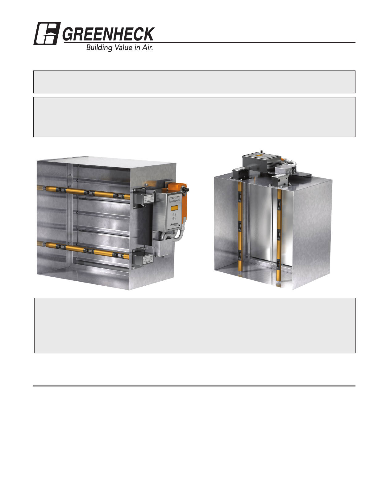
Setup and Operation for AMD-xx-TD Series Damper
All AMD-xx-TD’s are supplied with a Vari-Green®
airflow rate transmitter that is factory wired to one or
more Vari-Green airflow measurement probe(s). The
transmitter has been configured at the factory with
customer supplied parameters. For normal applications
the transmitter’s configuration should not need to be
modified in the field. However, if field configuration is
necessary please reference the Vari-Green transmitter
Installation, Operation, and Maintenance Manual
available at www.greenheck.com.
Once electrical power is applied, the transmitter
will go through a standard start-up sequence
during which it will identify and enable each airflow
sensor. This will take approximately 30 seconds.
Once the start-up sequence has been completed
the transmitter's display will show the measured
volumetric airflow rate, velocity, and ambient air
temperature (see below). Under normal operation a
dot in the upper right corner of the display will blink
rapidly (4 times per second).
You can order AMD-xx-TD’s with or without a factory supplied controller. When a factory supplied controller
is ordered, the controller can be configured for either analog operation or operation via a BACnet MS/TP
connection. Setup and operation for these different options are described on the following pages.
3
Page 4
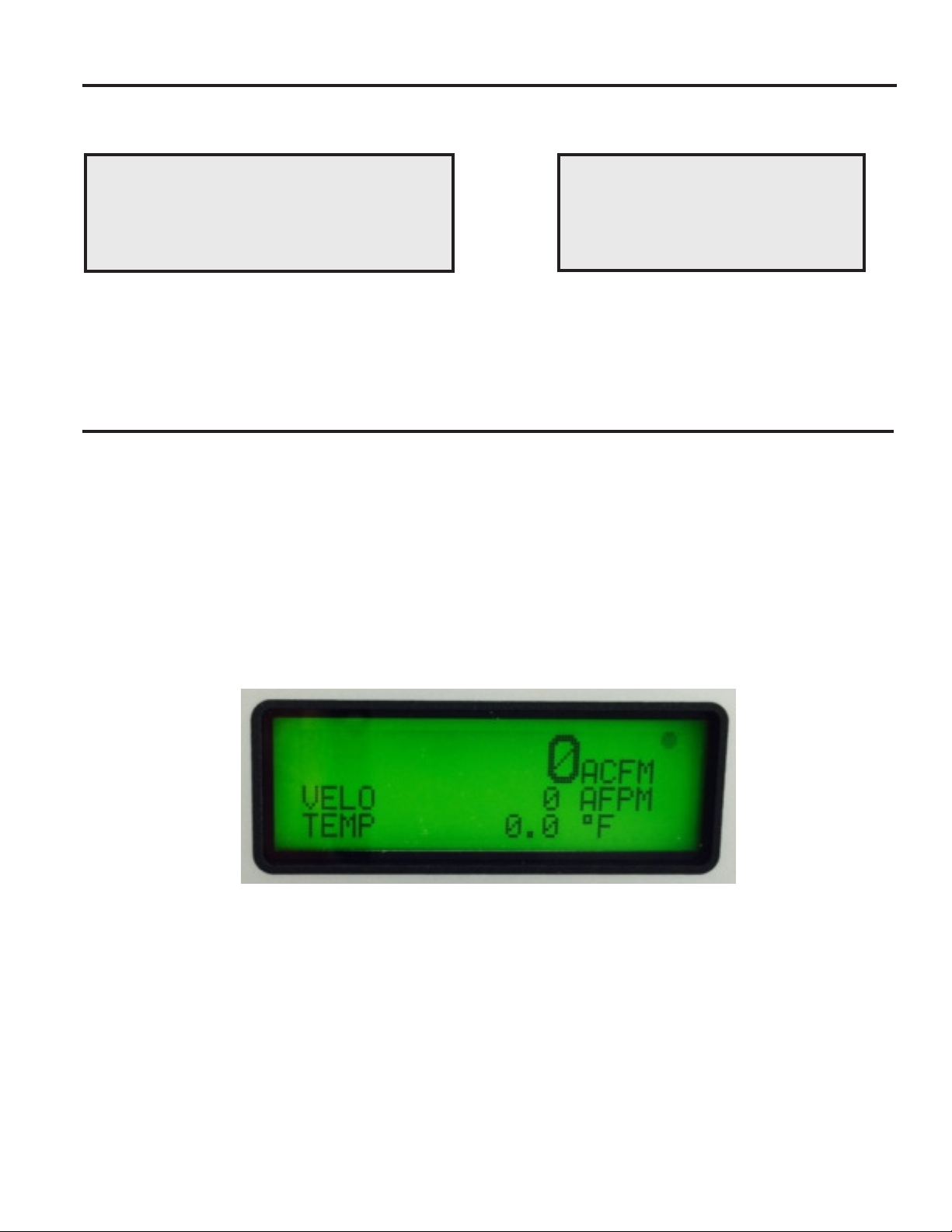
AMD-xx-TD Series Dampers without a Factory Supplied Controller
Units ordered without a factory supplied controller
are supplied with a standard modulating actuator.
The Vari-Green transmitter and actuator are wired to
a factory supplied terminal block. Figure 1 shows the
field wiring side of the terminal block.
The 0-10 VDC analog output at terminals 3 and
4 comes from the Vari-Green transmitter and is
proportional to the velocity going through the
AMD-xx-TD. A 10 VDC signal represents the
maximum velocity that was selected at the time the
unit was ordered. The selected maximum velocity
and the area of the AMD-xx-TD are listed on a label
adjacent to the terminal block. An example of how
you can determine the velocity and/or cfm going
through the unit is shown below.
Figure 1
Example 1: Determine the CFM from a 24 in.
x 24 in. AMD-xx-TD (area of 4 ft2) with a selected
maximum velocity of 2,000 fpm and a voltage reading
across terminals 3 and 4 of 3.5 VDC.
Measured Velocity = Max Velocity * (Measured Voltage / 10)
Measured Velocity = 2,000 * (3.5 / 10)
Measured Velocity = 700 fpm
and
Measured CFM = Measured Velocity * Area
Measured CFM = 700 fpm * 4 ft2
Measured CFM = 2,800 cfm
Factory Installed
Terminal Block
2 3
1
~
24VAC
0-10VDC Output
Proportional to
On multiple section high dampers, the
*** ***
actuators on the sections without the
terminal block will need to be field wired
4 5
S
Control
Signal to
Actuator
S
Flow
into Terminals 1, 2, & 5
7
6
AMD-XX-TD w/o Factory
Supplied Controller
8
9
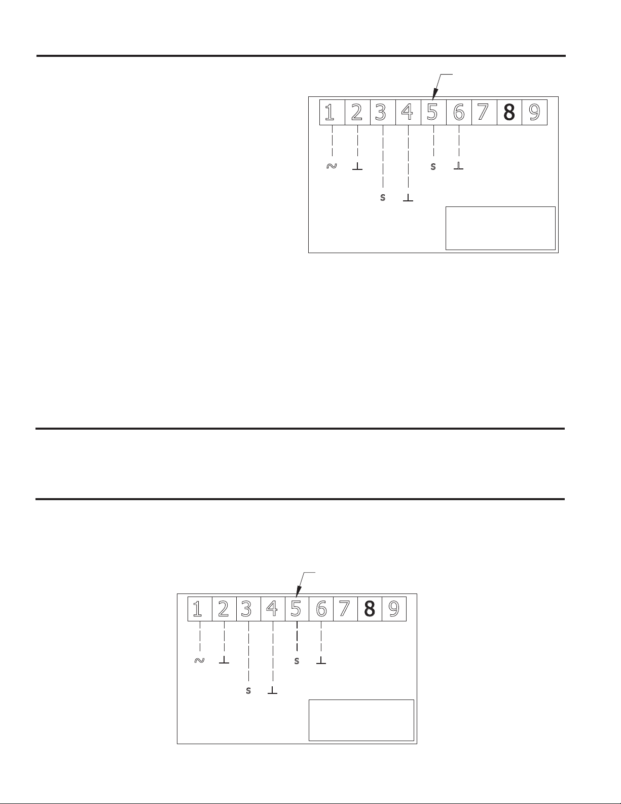
AMD-xx-TD’s Ordered with a Factory Supplied Controller
When you order a factory supplied controller, it comes with a Greenheck exclusive VAFB24-BAC-GTD actuator
which has the controller integrated inside of it. The actuator/controller is configured by the factory at the time
the unit is ordered for either analog or BACnet operation. This selection is made by setting the Setpoint Source
datapoint to Local AI or BACnet. A complete list of the all the BACnet datapoints is listed in Table 1 (page 7).
AMD-xx-TD Series Dampers with an Analog Factory Supplied Controller
Figure 2 shows field wiring for an AMD-xx-TD ordered with a factory supplied controller configured for analog
operation.
Factory Installed
Terminal Block
1
~
24VAC
Figure 2
S
4 5
Flow
2 3
0-10 VDC Output
Proportional to
S
0-10VDC
Input
Setpoint
7
6
AMD-XX-TD w/Analog
Factory Supplied
Controller
8
9
4
Page 5

The controller is designed to modulate the AMD-xxTD series damper such that it maintains a desired
cfm setpoint. The setpoint is supplied via a 0-10 VDC
analog input (terminals 5 and 6) that is proportional to
that setpoint. The Vari-Green transmitter will output
a 0-10 VDC signal (terminals 3 and 4) proportional
to the actual cfm being measured by the unit. For
both the desired cfm setpoint and the cfm output, a
voltage reading of 10 VDC represents the maximum
velocity that was selected at the time the product
was ordered. The selected maximum velocity and the
area of the AMD-xx-TD are listed on a label adjacent
to the terminal block. Example 2 shows how to
determine the voltage corresponding to the desired
cfm setpoint.
Example 2:
Determine the voltage setpoint that should be sent
to terminals 5 & 6 to achieve a flow of 4,800 CFM
on a 24 in. x 24 in. AMD-xx-TD (area of 4 ft2) with a
selected maximum velocity of 2,000 fpm.
Maximum CFM = 4 ft2 * 2,000 fpm = 8,000 cfm
Voltage Setpoint = 10 * (Desired CFM Setpoint /
Maximum CFM)
Voltage Setpoint = 10 *(4,800 / 8,000) = 6.0 VDC
See example 1 on how to convert the transmitter
voltage output (terminals 3 & 4) to cfm.
AMD-xx-TD Series Dampers with a BACnet Enabled Factory Supplied Controller
Figure 3 shows field wiring for an AMD-TD ordered with a factory supplied controller configured for a BACnet
MS/TP connection.
Factory Installed
Terminal Block
2 3
1
~
24VAC
Figure 3
This controller is designed to modulate the AMDxx-TD series damper such that it maintains a
desired cfm setpoint. The setpoint is established
by the BACnetSetpoint datapoint. Table 1 lists all
of the BACnet datapoints. The BACnetSetpoint is a
percentage of the MaxCFMSetpoint datapoint, which
is set at the factory based on the maximum velocity
which is selected at the time the unit is ordered.
4 5
Example 3: Determine the BACnet setpoint for a
24 in. x 24 in. AMD with a maximum velocity of 2,000
fpm and a target flow of 6,000 cfm.
MaxCFMSetpoint = 8,000 cfm (4 ft2 x 2,000 fpm)
BACnetSetpoint = (Target CFM / Maximum CFM)
BACnetSetpoint = (6,000 / 8,000) = 75%
With a BACnetSetpoint of 75% the actuator/controller
will position the damper to allow 6,000 cfm through it.
Position Control Mode
Example 3 applies when the actuator/controller is
in its factory default operating mode called “Flow
Control Mode”. However, for certain applications
it may be desirable to operate the AMD-TD as
7
6
Factory
Installed
Jumper
+ -
BACnet
MS/TP
AMD-XX-TD w/BACnet
MS/TP Factory
Supplied Controller
a standard modulating damper. This can be
accomplished by changing the DamperMode BACnet
data point (see Table 1) from CurrentAirflow to
DamperPosition. In “Position Control Mode” a
BACnetSetpoint of 75% will drive the damper 75%
open instead of finding a position that supplies 75%
of the maximum airflow.
8
9
Safety Override of the BACnet Setpoint
If your application requires the ability to locally
close the damper, the factory installed jumper wire
should be removed and replaced with a normally
closed “safety switch”. When the safety switch is
closed the damper will track the BACnetSetpoint as
if the jumper wire was left in place. When the safety
switch is open the actuator will power the damper
closed. Interlocking the damper with a fan such that
the damper closes when the fan shuts down is an
example of when the safety switch feature may be
utilized.
5
Page 6

Setting the Actuator/Controller's BACnet Configuration
The actuator’s BACnet configuration including the
device instance, MAC address, and baud rate can be
accessed through its Ethernet port.
Connecting to the Actuator
1. Using an Ethernet cable, connect the CAT 5
Ethernet port on your computer to the CAT 5 port
on your actuator.
2. Go into your computer’s Control Panel and access
the Local Area Connection
Windows 7 or 8
• Access the Network and Internet settings
then the Network Sharing Center
• Click on Change adapter settings then right
click on the Local Area Connection and
select Properties
Windows XP
• Open Network Connections
• Right click on the Local Area Connection
and select Properties
Access IP Address Settings
1. Select Internet Protocol
Windows 7 or 8
Select Internet Protocol Version 4 (TCP/IPv4)
the click on Properties
Windows XP
Select Internet Protocol (TCP/IP) the select
Properties
2. Change the IP Address to the value shown below.
Then hit the Tab key and the Subnet mask will
populate. Then click OK.
Access the Actuator
1. Open Internet Explorer and enter the following
address: http://192.168.0.10:8080/index.html
2. Enter "amdsetup" as the User Name and "gfcamd"
as the password.
Entering the BACnet Settings
1. Click on BACnet/MP settings.
2. Select MS/TP as Protocol
3. Configure the desired baud rate and MAC address
4. Choose unique Instance ID
5. Enter desired Device Name (optional)
6. Click Submit button
6
Page 7

BACnet Data Point List
Table 1 lists and describes all of the BACnet data points associated with the controller inside the actuator of
BACnet enabled AMD-TD series dampers.
Name Type # Access Description
Greenheck AMD-TD AI 1 C Displays the application version
AirflowSetpoint AI 2 C Displays the real-time setpoint in cfm
CurrentAirflow AI 3 C Displays the real-time volumetric airflow rate in cfm
AirVelocity AI 4 C Displays the real-time air velocity in fpm
DamperPosition AI 5 C Displays the real-time damper position as a percentage (0% - fully
closed; 100% fully open)
MaxCFMSetpoint AI 6 C Displays the maximum volumetric airflow rate in cfm. This value
is a function of the value selected for "Maximum FPM". (Max CFM
Setpoint = Damper Area * Maximum FPM).
DamperArea AV 1 C Represents the nominal damper face area in square feet. Set by the
factory.
MinimumFPMSetpoint AV 2 C Represents the minimum allowable velocity setpoint in fpm. If the
actuator receives a setpoint below the "Minimum FPM Setpoint" the
setpoint will be set to zero. The factory default value is 100 fpm.
BACnetSetpoint AV 3 C When the Setpoint Source is set to BACnet this variable establishes
the unit's setpoint. When the Damper Mode is set to Flow the BACnet
Setpoint is a percentage of the MaxCFM Setpoint. When the Damper
Mode is set to Position the BACnet Setpoint is the percentage the
damper is open. When the Setpoint Source is set not set to BACnet
this variable has no impact on controlling the damper.
SafetyStatus BI 1 C Represents the status of the safety circuit. Inactive = Open/Failure;
Active = Closed/OK
MaximumFPM MV 1 C Represents the maximum setpoint velocity in fpm. The value this
variable is set to corresponds to a 10 VDC input to the actuator. This
value is set at the factory based on maximum velocity that was
selected at the time the unit was ordered. 1 = 500 fpm; = 1000 fpm;
3 = 1500 fpm; 4 = 2000 fpm; 5 = 2500 fpm; 6 = 3000 fpm; 7 = 3500
fpm; 8 = 4000 fpm
DamperMode MV 2 C Establishes the mode of operation for the actuator. When in flow
control mode the actuator will view the setpoint as a target cfm to
maintain. When in position control mode the actuator will view the
setpoint percentage as a position to drive to (0% fully closed, 100%
fully open). Whether the actuator is in Flow or Position control mode
the source of the setpoint will be determined by the Setpoint Source
variable. 1 = Flow; 2 = Position
SetpointSource MV 3 C When set to BACnet the actuator uses the BACnet variable as the
setpoint. When set to Local AI it uses the actuator's second analog
input (S2) as the setpoint. When set to Zth the actuator uses a
handheld Zth module to establish the setpoint. 1 = BACnet; 2 = Local
AI; 3 = ZTH
AI - Analog Input
AO - Analog Output
AV - Analog Value
BI - Binary Input
BO - Binary Output
BV - Binary Value
MI - Multi-State Input
MO - Multi-State Output
MV - Multi-State Value
R - ReadOnly
W - Writable
C - Commandable
(Contains Priority Array)
7
Page 8

Protocol Implementation Conformation Statement - PICS
General Information
Date: 11. April 2014
Vendor Name: BELIMO Automation AG
Vendor ID: 423
Product Name: AFB24-OP GTD
Product Model Number: N/A
Applications Software Version: 1.34.0
Firmware Revision: 1.0.3
BACnet Protocol Revision: 1.6
Product Description:
The device is an air damper control actuator with the added benefit of a built-in programmable controller.
Free programming environment allows handling of a wide range of HVAC control applications. MP-Bus master
capabilities allow this device to monitor and control up to 15 additional slave devices that contain Belimo
MP-Bus technology, affording significant expandability. BACnet server functionality allows easy integration in
standard building automation systems. The commissioning of the device (BACnet Device Address, IP Address
settings, MS/TP Address …) is done via the integrated web-server.
BACnet Standard Device Profile: BACnet Application Specific Controller (B-ASC)
BACnet Interoperability Building Blocks supported:
Data Sharing - ReadProperty-B (DS-RP-B)
Data Sharing - ReadPropertyMultiple-B (DS-RPM-B)
Data Sharing - WriteProperty-B (DS-WP-B)
Device Management - DynamicDeviceBinding-B (DM-DDB-B)
Device Management - DynamicObjectBinding-B (DM-DOB-B)
Device Management - DeviceCommunicationControl-B (DM-DCC-B)
Segmentation Capability: No
Data Link Layer Options: BACnet IP, (Annex J)
BACnet IP, (Annex J), Foreign Device
MS/TP master,
baud rates: 9'600, 19'200, 38'400, 76'800, 115'200
Device Address Binding: No static device binding supported
Networking Options: None
Character Sets Supported: ANSI X3.4
Standard Objects
The device provides datapoints for common operation as well as datapoints for parameterization using the following object
types:
• Analog Input
• Analog Output
• Analog Value
• Binary Input
• Binary Output
• Binary Value
• Device
• Multi-State Input
• Multi-state Output
• Multi-state Value
8
Page 9

Object Processing
Object Type Optional Properties Writeable Properties
Analog Input Description
Analog Output Description Present_Value
Analog Value Description Present_Value
Binary Input Description
Binary Output Description
Binary Value Description
Device Description
Multistate Input Description
Multistate Value Description
Multistate Output Description
1)
Only if object is commandable.
2)
Only if MS/TP is the selected data link layer type
Active_Text
Inactive Text
Active_Text
Inactive_Text
Relinquish_Default
Priority_Array
Active_Text
Inactive_Text
Relinquish_Default
Priority_Array
Location
State_Text
State_Text
Relinquish_Default
Priority_Array
State_Text
Relinquish_Default
Priority_Array
1)
1)
1)
1)
Present_Value
1)
Present_Value
1)
Object_Identifier
Object_Name
Location
APDU_Timeout
Number_Of_APDU_Retries
Max_Master
Max_Info_Frames
Present_Value
1)
Present_Value
1)
2)
2)
• The properties Object_Name and Location of the Device Object support up to 255 characters (all other
character strings are read-only).
• The device does not support the CreateObject and DeleteObject service.
Service Processing
• The device supports DeviceCommunicationControl service. No password is required.
9
Page 10

Optimal Placement for AMD-TD Damper Series
Fans
2X
Centrifugal Fan Discharge
Centrifugal Fan Inlet
3X
Vane Axial Fan Discharge
3/4X
1X
Elbows
1/2X
90° Vaned Elbow
1X
Vane Axial Fan Inlet
1/2X
1.5X
90°Elbow Without Vanes
1/2X
10
Round Sweep Elbow
Page 11

Optimal Placement for AMD-TD Damper Series
Takeoffs
1X
Branch Takeoff B1
Transitions
1.5X
Branch Takeoff 2
Bellmouth Inlets
α
α
1/2X
Transition 1
α
α
1/2X
Transition 3
11
Page 12

Damper Maintenance
Greenheck's dampers are designed to be trouble free and hassle free under normal operation. Dampers are
to be installed square and straight so as to prevent binding during operation. The following annual damper
maintenance suggestions will help to insure proper damper operation and increase the life expectancy of the
damper.
Foreign Matter Over the course of time, dirt and grime may collect on damper surfaces. The
damper surfaces should be cleaned to prevent hindrance to airflow.
Moving Parts Make sure that parts such as linkage, bearings, blades, etc. that are intended
to move freely, can do so. Lubricating these components can prevent possible
rusting and unnecessary friction increase. Use only a moli-spray oil or similar
graphite based oil as regular lubricating oil will attract dirt.
Bearings: Synthetic, oil impregnated, and ball bearings (without grease fittings)
do not require lubrication. Ball bearings with grease fittings require only minimal
grease.
Closure Remove foreign materials that may be interfering with blade closure or effective
sealing of the blades with each other or with the frame.
Operation While operating the damper through its full cycle, check to see that the blades
open and close properly. If there is a problem, check for loose linkage, especially
at the actuator. Tighten the linkage where required.
Our Commitment
As a result of our commitment to continuous improvement, Greenheck reserves the right to change specifications without
notice.
Specific Greenheck product warranties can be located on greenheck.com within the product area tabs and listed in the
Library under Warranties.
®
Phone: (715) 359-6171 • Fax: (715) 355-2399 • E-mail: gfcinfo@greenheck.com • Website: www.greenheck.com
478799 • AMS & AMD, Rev. 1, March 2014 Copyright 2014 © Greenheck Fan Corporation
 Loading...