

Page 1
®
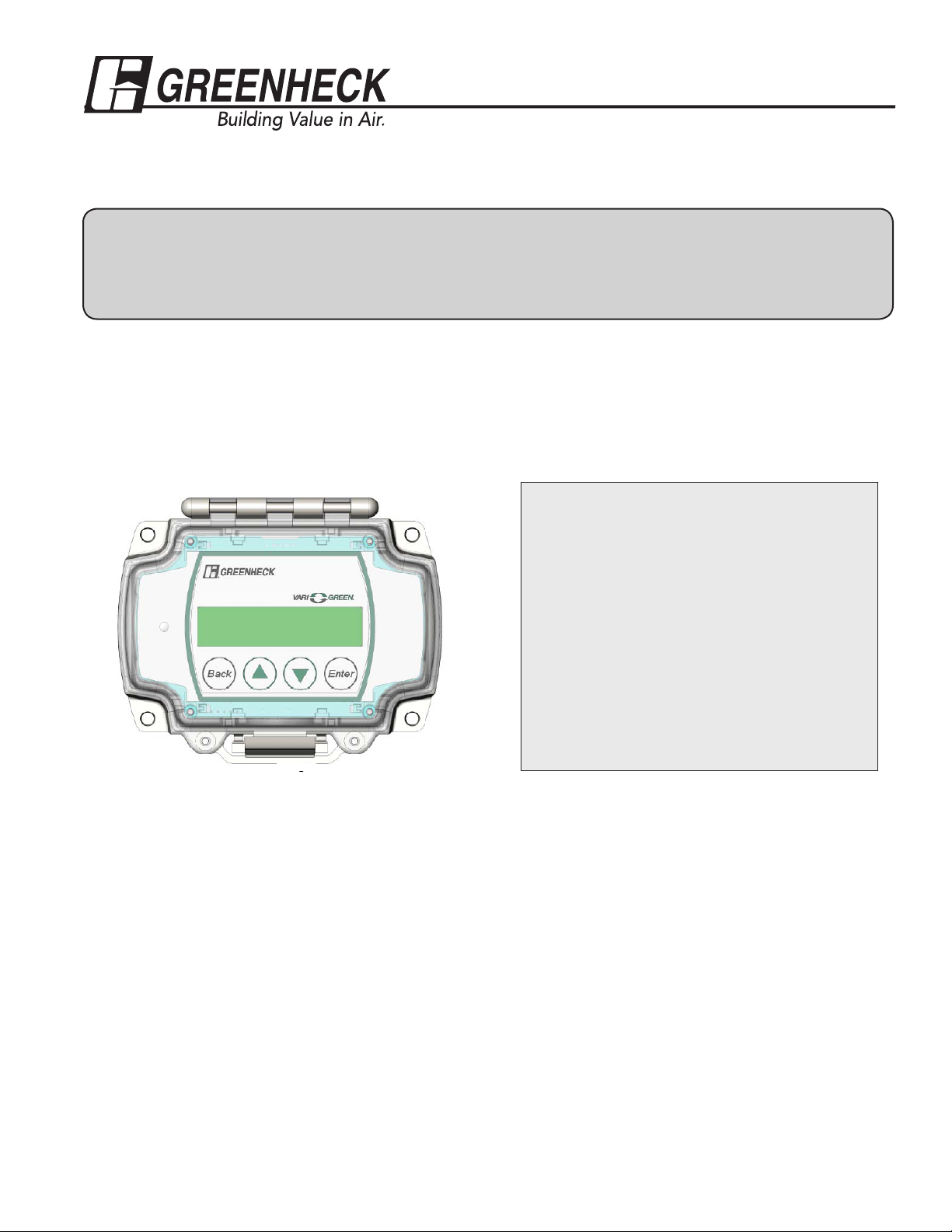
Vari-Green Constant Volume Controller
for AMS & AMD Damper Series
Installation, Operation and Maintenance Manual
Please read and save these instructions for future reference. Read carefully before attempting to assemble, install,
operate or maintain the product described. Protect yourself and others by observing all safety information. Failure to
comply with instructions could result in personal injury and/or property damage!
These instructions apply to Greenheck’s Vari-Green Constant Volume damper controller. The controller accepts
an analog output from a factory supplied pressure transducer on a Greenheck AMS airflow measuring station
or AMD airflow measuring damper to calculate the realtime volumetric airflow rate (cfm) going through the unit.
Using PID logic the controller then controls the damper’s actuator to achieve a target cfm setpoint. The cfm
setpoint can be established either remotely via an analog input to the controller or locally using touch sensitive
buttons on the cover of the controller.
Table of Contents
General Operation of the Controller .............2
• Setting the Flow Setpoint ...................... 2
• Airflow Output Signal ............................. 2
Document number 479830
Constant Volume
Varigreen Damper
Controller
Controller Display and Interface Buttons ...2-3
Controller Configuration ............................3-6
• Factory Configuration .........................3-4
• Field Configuration ..............................4-6
• Manual Control ......................................6
• Factory Defaults ....................................6
Diagnostic LED ............................................. 7
Wiring of Controller ...................................7-8
Receiving
Upon receiving the control, check to ensure all items are
accounted for by referencing the delivery receipt or packing
list. Inspect each crate or carton for shipping damage
before accepting delivery. Alert the carrier of any damage
detected. The customer will make notification of damage
(or shortage of items) on the delivery receipt and all copies
of the bill of lading which is countersigned by the delivering
carrier. If damaged, immediately contact your Greenheck
Representative. Any physical damage to the unit after
acceptance is not the responsibility of Greenheck Fan
Corporation.
Unpacking
Verify that all required parts and the correct quantity of
each item have been received. If any items are missing,
report shortages to your local representative to arrange for
obtaining missing parts.
Storage
Controls are protected against damage during shipment. If
the control cannot be installed and operated immediately,
precautions need to be taken to prevent deterioration of
the control during storage. The user assumes responsibility
of the control and any accessories while in storage. The
manufacturer will not be responsible for damage during
storage. These suggestions are provided solely as a
convenience to the user.
Indoor
The ideal environment for the storage of controls is indoors,
above grade, in a low humidity atmosphere which is
sealed to prevent the entry of blowing dust, rain or snow.
Temperatures should be evenly maintained between 30° to
110°F (-1° to 43°C). Wide temperature swings may cause
condensation and “sweating” of metal parts. All accessories
must be stored indoors in a clean, dry atmosphere.
Removing from Storage
As controls are removed from storage to be installed in their
final location, they should be protected and maintained in a
similar fashion until the control goes into operation.
1
Page 2
General Operation of the Controller
The Vari-Green Constant Volume Controller has two operating modes. The controller is factory set to its Flow Control
Mode. In Flow Control Mode the controller will modulate the position of the damper to achieve a target airflow setpoint. The
controller can also be put into Position Control Mode. In Position Control Mode the controller treats the setpoint as a target
damper blade position.
In addition to the two operating modes the controller has a parameter called Setpoint Location that can be configured to
either Remote or Local. The controller ships from the factory with the Setpoint Location set to Remote. In Remote mode the
controller uses a voltage sent to one of its analog inputs to establish the setpoint (see the Setting the Flow Setpoint section
below). When the Setpoint Location is in Local mode the interface on the front cover of the controller is used to establish the
setpoint and the voltage sent to the analog input is ignored.
See the Field Configuration section of this document to learn how to change the Control Mode and Setpoint Location. The
following section assumes that the controller is in the factory default Flow Control and Remote Setpoint Location modes.
Setting the Flow Setpoint
The controller accepts an analog input (configurable for
either 0-10 or 2-10 VDC) that is proportional to a target
volumetric airflow rate (cfm). The voltage corresponding to
the setpoint can be determined using the following formulas:
0 - 10 VDC setpoint
C = Q /(V
2 - 10 VDC setpoint
C = Q /(V
Formula 1
Where:
C = Flow Setpoint (VDC)
Q = Desired Airflow (cfm)
V
= Maximum Velocity as specified at the time the unit
max
was ordered (fpm)
A = Face Area of the Damper (ft2)
max
* A) * 8 + 2
max
* A) * 10
Airflow Output Signal
The controller outputs an analog signal (configurable for
either 0-10 or 2-10 VDC) that is proportional to the real-time
airflow rate (cfm) going through the AMD/AMS. The cfm
corresponding to the voltage output can be determined
using the following formulas:
0 - 10 VDC setpoint
Q = (C * V
max
* A) /10
2 - 10 VDC setpoint
Q = ((C - 2) * V
max
* A) /8
Formula 2
Where:
C = Voltage Output Signal (VDC)
Q = Real-time Airflow (cfm)
V max = Maximum Velocity as specified at the time the unit
was ordered (fpm)
A = Face Area of the Damper (ft2)
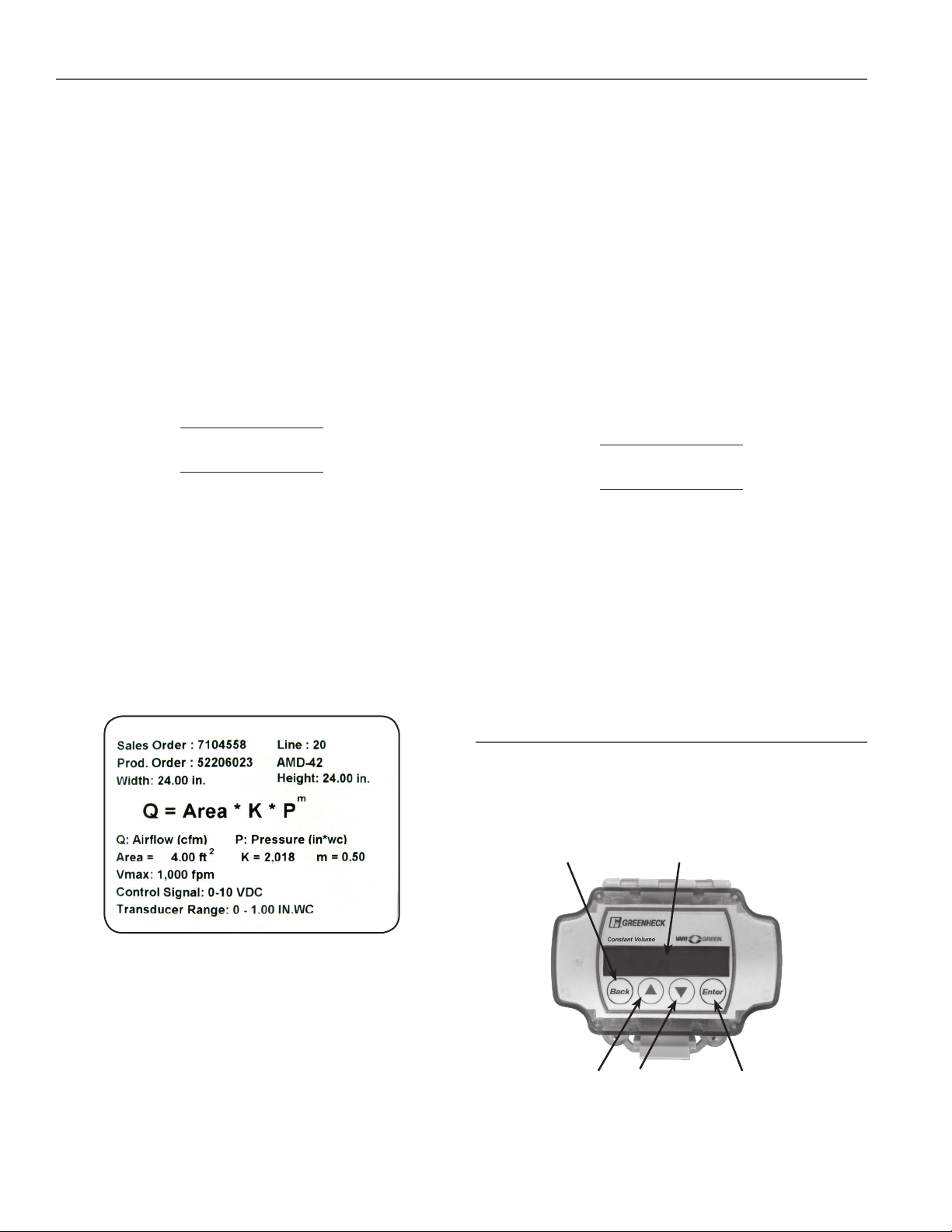
Controller Display and Interface
Buttons
There are four touch sensitive buttons on the controller’s
cover that are used to interface with the controller: Back,
Enter, Up and Down (see Figure 2).
Figure 1 - Label affixed to AMS/AMD that
lists the V
Example: The BMS desires 2,000 cfm through a
24 in. x 24 in. AMD-42 that was ordered with a maximum
velocity of 1,000 fpm. Find the voltage setpoint that
corresponds to 2,000 cfm:
C = 2,000 / (1,000 * 4) * 10 = 5 VDC (0-10 VDC)
C = 2,000 / (1,000 * 4) * 8 +2 = 6 VDC (2-10 VDC)
2
and damper area.
max
DisplayBack Button
Up Arrow
Figure 2 - Outside of the controller's cover
Down Arrow Enter Button
Page 3
Controller Display and Interface Buttons cont...
The controller also has a two line backlit LCD display. By
using the up and down arrows the display can be toggled
through three sets of data:
XXXXX CFM
Setpt XXXXX CFM
• Top Screen: Real-Time CFM and CFM Setpoint
• Middle Screen: Real-Time Velocity (fpm) and Velocity
Setpoint
XXXX FPM
Setpt XXXX FPM
• Bottom Screen: Real-Time Differential Pressure
Measurement and Actuator Position
X.XX in WC
Act XX.X% Open
Figure 3 - Run Mode display screens
Controller Configuration
The Vari-Green Constant Volume Controller is shipped in “Run Mode”. When calculating the airflow rate going through the
AMS/AMD and to control the damper (on AMD models) the controller should be left in run mode. In most cases the controller
should not need to be taken out of run mode. However, a variety of parameters can be adjusted in the field as needed by
opening the controller’s cover and moving the toggle switch into the PROG position (see Figure 2).
When in program mode the display can be toggled through a “Top Level Menu” by using the up and down arrows on the
controller’s cover (see Figure 4). The desired menu item can be accessed by pressing the “Enter” button.
Factory Config
Enter to Select
Field Config
Enter to Select
Manual Control
Enter to Select
Factory Defaults
Enter to Select
Figure 4 - Top level menu in Program Mode.
Factory Configuration
The controller comes from the factory configured with the
physical parameters of the AMD/AMS it was ordered with.
These parameters include:
• Flow Measurement Device – should always be left as
“Diff Pressure”
• The unit’s K & M Values – damper specific constants
used to calculate airflow. These values are set at the
factory and can also be found on the label affixed to
the AMD/AMS (see Figure 1)
• Maximum Pressure – this parameter represents
the top-end of the AMD/AMS pressure transducer
range. The selectable values are: 0.25” wc, 0.5” wc,
1.0” wc, 2.0” wc, 2.5” wc, 3.0” wc, and 5.0” wc. The
maximum pressure is also a configurable value on the
pressure transducer (see the transducer instructions).
The top-end of the controller’s pressure range and
the transducer’s pressure range must match for the
controller to operate properly. They are set at the
factory to the same values.
• Damper Area - the face area of the AMD/AMS
(ft2)
• Maximum Velocity – this parameter represents
the velocity corresponding to a 10 VDC remote
setpoint. This parameter is set by the factory to the
value selected at the time the unit was ordered.
The selectable values are: 500 fpm, 1000 fpm, 1500
fpm, 2000 fpm, 2500 fpm, 3000 fpm, 3500 fpm and
4000 fpm. To achieve optimal accuracy the lowest
value that meets the application should be selected.
Changing the maximum velocity value will affect
the flow setpoint and flow output calculations. See
formulas 1 and 2 on page 2.
• Minimum Velocity – this is the minimum velocity
the unit is designed to accurately measure airflow
and control the damper at. To avoid “hunting” the
controller will treat setpoints below the minimum
velocity as a setpoint of zero. The controller is set to a
value of 300 fpm at the factory.
While the parameters in the factory configuration menu
don’t normally require adjustment, they can be changed by
putting the controller into Program Mode (see above) and
then pressing enter on the “Factory Config” option in the top
level menu. The factory configuration menu structure, see
Figure 5, can be navigated by using the up and down arrows
on the controller’s cover. When the parameter you wish to
adjust is shown in the display press the "Enter" button to
enter the edit mode. The parameter can then be adjusted
by using the up and down arrows (parameter will blink
on display when in edit mode). Once the desired value is
selected press "Enter" again to leave edit mode. Once all of
the parameters have been adjusted press the "Back" button
on the controller to return to the top level menu or return the
slider switch inside the controller to run mode.
3
Page 4

Return
Flow Measure Dev
Thermal Disp
Flow Measure Dev
Diff Pressure
AMD “K” Value
2000
AMD “M” Value
0.5
Maximum Pressure
1.00 in WC
Damper Area
4.00 ft^2
Maximum Velocity
2,000 FPM
Minimum Velocity
300 FPM
Figure 5 - Factory Configuration Menu Structure
Field Configuration
The controller comes from the factory with the parameters
in the field configuration menu (see Figure 6) set to the most
commonly used values. The field configuration menu can
be accessed from the top level menu (see Figure 4).These
parameters include:
• Units of Measure – the controller comes with imperial
units selected. The controller can be configured to
display in metric units.
• Actuator Setpoint – this parameter sets the type of
analog output signal the controller will use to control
the damper’s actuator. The default selection is 2-10
VDC, but the controller can be configured to send a
0-10 VDC signal to the actuator.
• Velocity Output – this parameter sets the type of
analog signal the controller uses to output the airflow
rate. The default selection is 0-10 VDC, but the
controller can be configured to output a 2-10 VDC
signal.
• Control Mode – this parameter determines how the
controller treats the setpoint. The default selection
is Flow Control mode. In Flow Control mode the
controller treats the setpoint as the desired airflow
(cfm). See the section on Setting the Flow Setpoint.
The controller can also be put into Position Control
mode. In this mode the controller treats the setpoint
as the desired position of the actuator.
• Setpoint Location – this parameter determines where
the controller gets its setpoint from. The default
setpoint location is Remote. In Remote setpoint
location mode the controller uses the signal from its
analog input as the target setpoint. See the section
on Setting the Flow Setpoint. The controller can also
be put into Local setpoint location mode. In Local
setpoint location mode the controller will ask for a
Flow or Damper Position setpoint (depending on the
selected control mode) to be entered using the up
and down arrows on the controller’s cover when in the
Field Configuration Menu (see the Field Configuration
menu structure). When the controller’s toggle switch is
moved back into run mode it will control the damper
to the entered setpoint instead of the value sent to
the analog input. Local setpoint mode should be used
when the desired flow or position setpoint is constant.
• Setpoint Input - this parameter sets the type of analog
signal that will be sent to the controller as the remote
setpoint. The default selection is 0-10 VDC, but the
controller can be configured to accept a 2-10 VDC
signal.
• Field Correction – this parameter can be used to
adjust the airflow calculation of the controller. The
default value is 1.0. Changing this value will adjust the
calculated flow proportionally. For example, setting
the Field Correction factor to 0.95 will reduce the
calculated flow values by 5%. Setting it to 1.05 will
increase the calculated flow by 5%.
• Air Density Correction – this parameter adjusts the
airflow calculation to account for changes in the dry
bulb temperature of the air being measured and/or the
elevation above sea level of the jobsite. The default
value is 1.00, which corresponds to an air temperature
of 70° F and an elevation of 0 ft. Table 1 shows the Air
Density Correction as a function of air temperature
and elevation
• Response Time – this parameter determines how
the controller responds to changes in the setpoint or
system conditions. The controller has three available
response times. It comes from the factory set to
the fastest response time. If, because of system
conditions, the controller is “hunting” without settling
on a point one of the slower response times should be
selected. The Medium response time should be tried
first. If the controller is still not settling on a point the
Slow setting should be used.
4
Page 5

Field Configuration cont....
• Control Deadband – this parameter determines the
range of acceptable values around the setpoint that
the controller will attempt to achieve. The factory
default Control Deadband is 25 fpm. As an example,
with a 25 fpm deadband and a setpoint of 1,000 fpm
the controller will adjust the damper’s position until the
real-time velocity is between 975 fpm and 1,025 fpm
(note that fpm can be converted to cfm by multiplying
by the AMD/AMS area). Larger deadbands will make it
easier for the controller to reach an acceptable point,
but may result in the realtime flow being further from
the setpoint.
• Override Out – the controller has a voltage free non-
grounded contact that can be used to override the
normal operation of the controller. When the contact is
Units of Measure
Imperial
Actuator Setpnt
0 to 10 VDC
open the controller functions normally. However, if the
contact is closed the controller will drive the actuator
to an override position. The override position is set to
100% open from the factory, but may be adjusted to
any position between 0 and 100%.
• Sensor Filter – this parameter establishes the amount
of averaging the controller performs on the pressure
reading before it updates the airflow calculation. The
factory default setting is 3 seconds. The value should
not be adjusted below 3 seconds and should only be
increased above 3 seconds if turbulence such as wind
gusts result in sporadic airflow measurement readings.
If the sensor filter is increased above 3 seconds one of
the slower response time settings will likely need to be
used to avoid the actuator hunting for the setpoint.
Units of Measure
Metric
Actuator Setpnt
2 to 10 VDC
Setpoint Input
0 to 10 VDC
Setpoint
Location: Remote
Setpoint Input
2 to 10 VDC
Response Time
Fast
Velocity Output
0 to 10 VDC
Control Mode
Flow
Setpoint
Location: Local
Flow Setpoint
XXXX CFM
Field Correction
1.00
Air Density Corr
1.00
Response Time
Medium
Control Deadband
20 FPM
Velocity Output
2 to 10 VDC
Control Mode
Position
Setpoint
Location: Local
Damp Pos Setpnt
XX%
Response Time
Slow
Setpoint Input
0 to 10 VDC
Setpoint
Location: Remote
Setpoint Input
2 to 10 VDC
Override Out %
100%
Sensor Filter
0 Seconds
Return
Figure 6- Field Configuration Menu Structure
5
Page 6

Duct Air
Temp
°F
(Deg. C)
-40 (-40) 0.79 0.81 0.82 0.84 0.85 0.87 0.88 0.9 0.92 0.93 0.95 0.97 0.99
-20 (-29) 0.83 0.85 0.86 0.88 0.89 0.91 0.93 0.94 0.96 0.98 0.99 1.02 1.04
0 (-18) 0.87 0.88 0.9 0.92 0.93 0.95 0.97 0.99 1 1.02 1.04 1.06 1.08
20 (-7) 0.91 0.92 0.94 0.96 0.97 0.99 1.01 1.03 1.05 1.07 1.08 1.11 1.13
40 (4) 0.94 0.96 0.98 1 1.01 1.03 1.05 1.07 1.09 1.11 1.13 1.16 1.18
70 (21) 1 1.02 1.04 1.06 1.08 1.1 1.12 1.14 1.16 1.18 1.2 1.22 1.25
80 (27) 1.02 1.04 1.06 1.08 1.1 1.12 1.14 1.16 1.18 1.2 1.22 1.25 1.27
100 (38) 1.06 1.08 1.1 1.12 1.14 1.16 1.18 1.2 1.22 1.25 1.27 1.29 1.32
120 (49) 1.09 1.11 1.13 1.16 1.18 1.2 1.22 1.24 1.27 1.29 1.31 1.34 1.37
140 (60) 1.13 1.15 1.17 1.2 1.22 1.24 1.26 1.29 1.31 1.34 1.36 1.39 1.41
160 (71) 1.17 1.19 1.21 1.24 1.26 1.28 1.31 1.33 1.35 1.38 1.4 1.43 1.46
180 (82) 1.21 1.23 1.25 1.28 1.3 1.32 1.35 1.37 1.4 1.42 1.45 1.48 1.51
200 (93) 1.25 1.27 1.29 1.32 1.34 1.36 1.39 1.42 1.44 1.47 1.49 1.53 1.55
0 500 1000 1500 2000 2500 3000 3500 4000 4500 5000 5500 6000
(0) (152.4) (304.8) (457.2) (609.6) (762) (914.4) (1066.8) (1219.2) (1371.6) (1524) (1676.4) (1828.8)
Air Density Correction Factors
Elevation Dimensions in feet and (meters)
Table 1 - Air Density Correction Factor
Manual Control
Manual Control mode allows the user to directly change the percent the damper is open by using the up and down arrows
on the controller’s cover. This can be done by entering the top level menu, scrolling down to Manual Control, and pressing
"Enter". You can leave Manual Control mode at any time by pressing the "Back" button or by putting the slider switch inside
the controller back into the run position.
Factory Defaults
For trouble shooting purposes, it may be desirable to reset the controller’s parameters back to the factory defaults. This can
be done by entering the top level menu, scrolling down to “Factory Defaults” and pressing enter. You will see an option to
“Resort Factory Defaults”. Select Yes and then select Yes again when asked “Are You Sure?”. Once this is done you will need
to go through each parameter in both the factory and field configuration menus and select the appropriate value.
6
Page 7

Diagnostic LED
Wiring the Controller
The controller has a multicolor LED that is used to
distinguish between operating modes and to indicate
trouble conditions.
• Solid Green – Flow Control with Remote Setpoint
(Control Mode = Flow; Setpoint Source = Remote;
Request Velocity >= Minimum Velocity)
• Blinking Green – Flow Control with Local Setpoint
(Control Mode = Flow; Setpoint Source = Local;
Request Velocity >= Minimum Velocity)
• Solid Blue – Position Control with Remote Setpoint
(Control Mode = Position Setpoint Source = Remote;
Request Velocity >= Minimum Velocity)
• Blinking Blue – Position Control with Local Setpoint
(Control Mode = Position Setpoint Source = Local;
Request Velocity >= Minimum Velocity)
• Solid Purple – Parameter Editing or Manual Mode
• Solid Pink – Override activated
• Blinking Yellow – Low Velocity Setpoint. The LED will
blink yellow when the requested velocity is greater
than 20 fpm, but less than the minimum velocity
parameter. This indicates that the user is sending
a velocity request, but that it is under the defined
minimum velocity.
• Blinking Red – No Velocity Setpoint. When in Remote
Setpoint Source mode regardless of the control mode,
if the velocity request is less than 20 fpm the LED
should blink red.
The basic wiring of the controller is shown below in Figure
7. The controller’s three terminal blocks can be accessed by
opening the cover of the enclosure.
Powering the Controller
The controller is powered by applying electrical power to the
“Power In” terminal block. The controller can run off of 24
VAC +/- 20% 50/60 Hz or 24 VDC +/- 10%
Connecting the Pressure Transducer
The second terminal block is labeled “Remote Sensor” and
is used to connect to the pressure transducer. The three
terminals from the Remote Sensor block connect directly to
the pressure transducer as shown in Figure 6. The controller
supplies the transducer with its power and reads the
pressure signal.
Connecting the Damper Actuator
The actuator can be powered either by the same power
supply as the controller, as shown in Figure 7, or by running
a separate power supply to terminals 4 and 5 of the factory
supplied terminal block on the AMD/AMS. In addition, the
“Control Out” from the controller (terminal 7) must be run to
terminal 6 on the damper’s terminal block.
Connecting the Flow (or position) Setpoint Signal
Connect the 0-10 VDC or 2-10 VDC flow (or position)
setpoint to the controller terminals 1 and 3. The controller’s
terminal 1, labeled Remote Setpoint, is the positive terminal
and the controller’s terminal 3 is the common terminal.
Connecting to the Flow Output Signal
Connecting to controller terminals 6 and 3 allows the
user to read the 0-10 VDC or 2-10 VDC flow output that
is proportional to the cfm measured by the AMD/AMS. To
convert the voltage signal to cfm see the section above on
Airflow Output Signal.
Override Mode
The functionality of the override feature is described above
in the Field Configuration section of this document. The
override feature can be activated by closing the contacts
of an external relay across terminals 2 and 3 (or by simply
putting a jumper wire across them).
7
Page 8

Vari-Green Constant Volume Controller Wiring Diagram
Remote Transducer
Wiring Connector
Control Wiring
Connector
PROG/RUN
Switch
Power Wiring
Connector
All wiring above terminal block done at factory
when the actuator is externally mounted. When
the actuator is internally mounted the actuator
must be wired to the terminal block in the field.
Figure 7 - Basic Wiring of Vari-Green Constant Pressure Controller
Our Commitment
As a result of our commitment to continuous improvement, Greenheck reserves the right to change specifications without
notice.
Specific Greenheck product warrantees can be located on greenheck.com within the product area tabs and listed in the
Library under Warrantees.
®
Phone: (715) 359-6171 • Fax: (715) 355-2399 • E-mail: gfcinfo@greenheck.com • Website: www.greenheck.com
479830 • BAPI Controller for AMD & AMS, Rev. 1, April 2015 Copyright 2015 © Greenheck Fan Corporation
 Loading...