

Page 1
Document number 474014
®
AMS & AMD Damper Series
Installation, Operation, and Maintenance Instructions
This manual is the property of the owner, and is required for future maintenance. Please leave it with the owner when the
job is complete.
SAFETY WARNING:
Improper installation, adjustment, alteration, service or maintenance can cause property damage,
injury or death. Read the installation, operating, and maintenance instructions thoroughly before
installing or servicing this equipment.
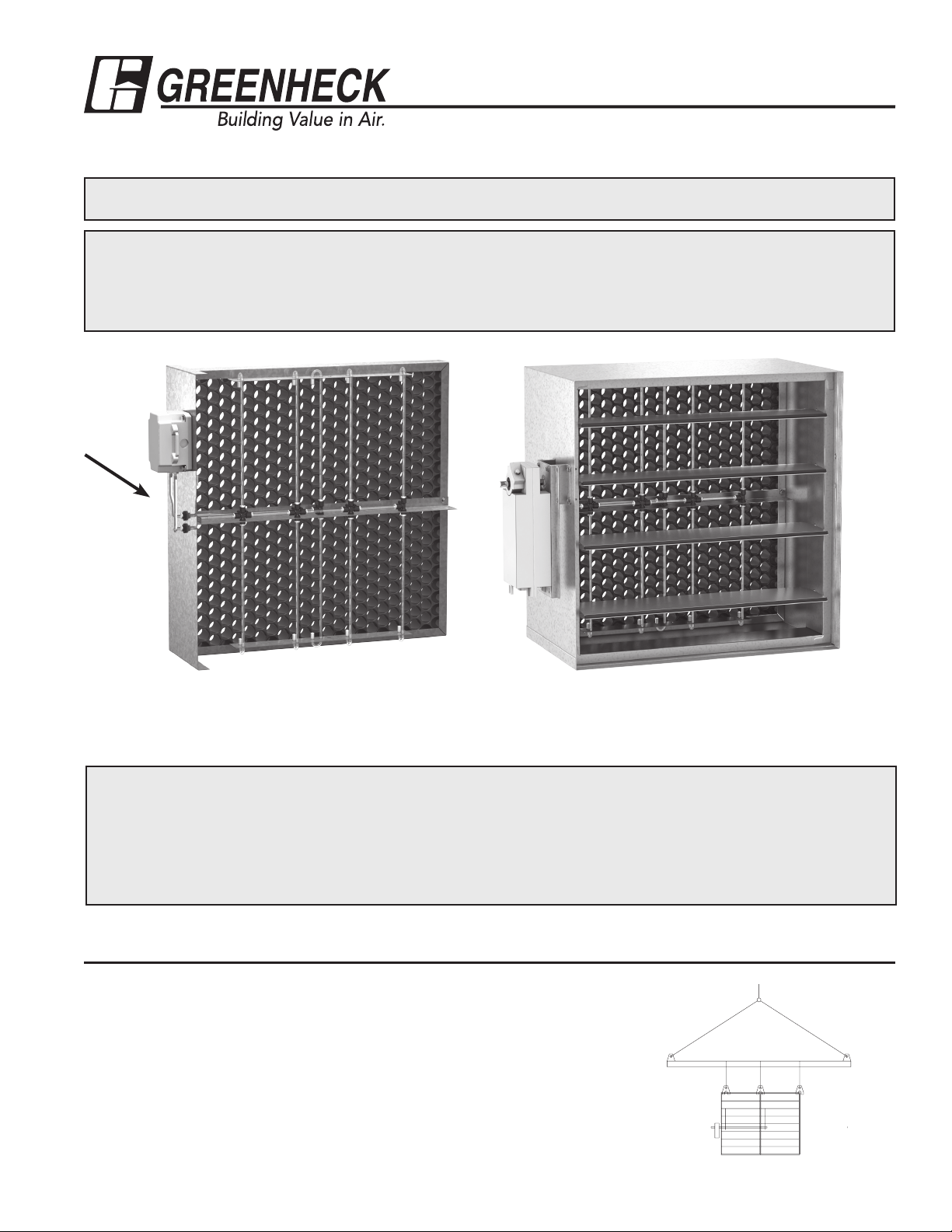
Airflow
AMS
AMD-42
Note: A minimum velocity of 300 fpm (1.5 m/s) is required.
RECEIVING AND HANDLING
Upon receiving dampers, check for both obvious and hidden damage. If damage is found, record all necessary
information on the bill of lading and file a claim with the final carrier. Check to be sure that all parts of the
shipment, including accessories, are accounted for.
Dampers must be kept dry and clean. Indoor storage and protection from dirt, dust and the weather is highly
recommended. Do not store at temperatures in excess of 100°F (37ºC).
Due to continuing research, Greenheck reserves the right to change specifications without notice.
Pre-Installation Guidelines
The basic intent of a proper installation is to secure the
AMS & AMD series damper into the opening in such a
manner as to prevent distortion and disruption of damper
operation. The following items will aid in completing the
damper installation in a timely and effective manner.
1) Check the schedules for proper damper locations within
the building. Visually inspect the damper for damage.
2) Lift or handle damper using sleeve or frame. Do not
lift damper using blades, linkage, actuators, pickups, or jackshafting. When handling multiple sections
assemblies, use sufficient support to evenly lift at each
section mullion (see drawing). Do not drag, step on,
apply excessive
bending, twisting, or
racking.
3) Do not install
screws in damper
frame that will
interfere with
unexposed blade
linkage and prevent
damper blades from
opening and/or
closing.
Spreader Bar
Attachments
Multi section dampers
Page 2
Pre-Installation Guidelines
4) Damper must be installed into duct or opening square
and free of twist or other misalignment. Damper must
not be squeezed or stretched into duct or opening. Out
of square, racked, twisted or misaligned installations can
cause excessive leakage and/or torque requirements to
exceed damper/actuator design.
5) Damper and actuator must be kept clean, dry and
protected from dirt, dust and other foreign materials
prior to and after installation. Examples of such foreign
materials include but are not limited to:
a) Mortar dust
b) Drywall dust
e) Paint overspray
6) Damper should be sufficiently covered as to prevent
overspray if wall texturing or spray painting will be
performed within 5 feet (1.5m) of the damper. Excessive
dirt or foreign material deposits on damper can cause
excessive leakage and/or torque requirements and
inaccurate airflow measurement to exceed damper/
actuator design.
7) ACCESS: Suitable access (actuators maintenance, etc.)
must be provided for damper inspection and servicing.
Where it is not possible to achieve sufficient size access,
it will be necessary to install a removable section of duct.
c) Firesafing materials
d) Wall texture
Installation- Failure to follow instructions will void all warranties
1. Ensure the AMS or AMD series damper is mounted with
airflow straightener upstream of the damper.
2. Duct opening or opening square should measure 1/4
inch (6mm) larger than damper dimension and should be
straight and level.
3. Use shims between damper frame and duct opening or
opening space to prevent distortion of frame by fasteners
holding it in place. Brace at every horizontal mullion and
vertically brace at every 8 feet (2.4m) of damper width for
strength. Dampers in high velocity (2000 fpm [610m per
second]) may require more bracing.
Note: Greenheck dampers are specifically designed
and engineered for structural integrity based on model
and conditions. Attachment, framing, mating flanges,
and anchoring of damper assemblies into openings,
ductwork, or walls is the responsibility of the installer.
Design calculations for these retaining and supporting
members should be determined by field engineers for
that particular installation.
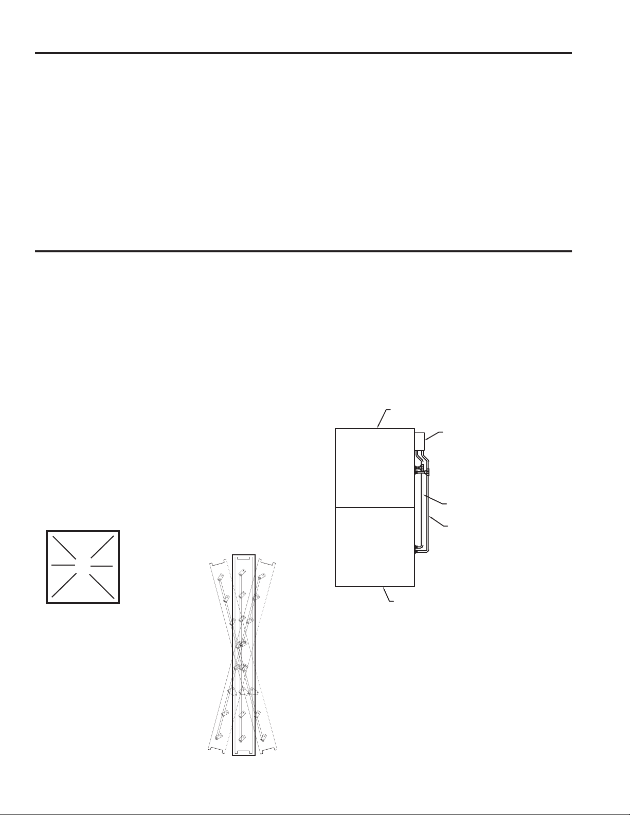
4. Individual damper sections, as well as entire multiple
section assemblies must be completely square and free
from racking, twisting, or bending. Measure diagonally
from upper corners to opposite lower corners of each
A
B
section.
5. Damper blades, axles, and linkage must operate without
binding. Before system operation, cycle dampers after
installation to assure proper operation. On multiple
section assemblies all sections should open and close
simultaneously.
6) Installing two section high AMD series together. AMD's
more than one section high will be shipped separately in
individual sleeves. The high and low pressure ports need
to be plumbed together and then plumbed back to the
pressure transducer.
Damper Sleeve
Pressure Transducer
Plumb the high pressure parts together
Plumb the low pressure parts together
C
E
Do not twist
or bow. Mount
damper plumb
in the opening.
2
AF = BE
AB = CD
D
F
Damper Sleeve
Page 3
Electrical Guidelines
Electrical and/or pneumatic connections to damper actuators should be made in accordance with wiring and piping
diagrams developed in compliance with applicable codes, ordinances and regulations.
SAFETY CAUTION !
Verify power requirements before wiring actuator.
Greenheck is not responsible for any damage to, or
failure of the unit caused by incorrect field wiring.
Connect electrical connection to terminal strip as shown on drawing (see figure 1).
Electrical input may be needed for this
equipment. This work should be performed
SAFETY DANGER !
by a qualified electrician.
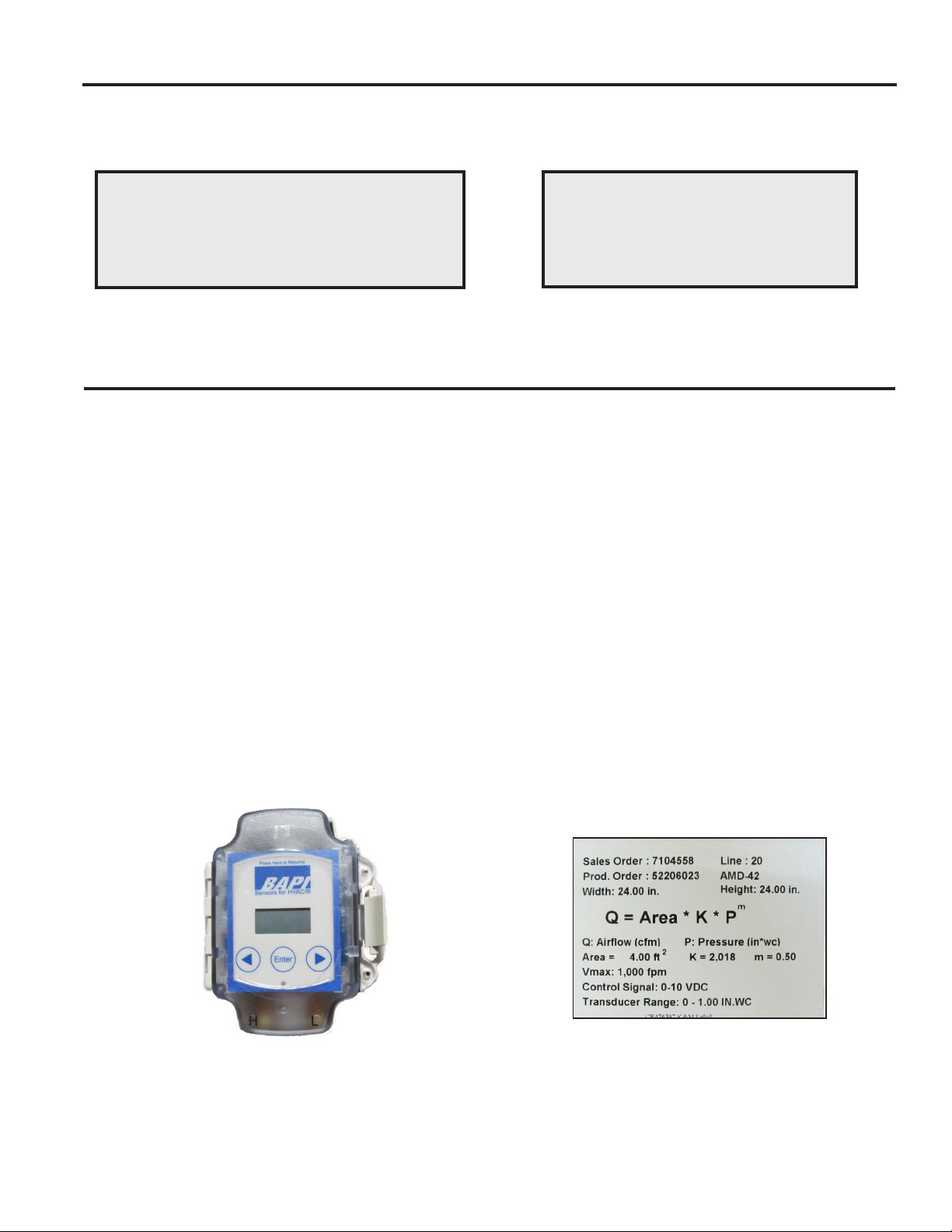
Setup and Operation for AMS and AMD Series Without Factory Supplied Controller
Each AMD and AMS is shipped with a highly accurate pressure transducer (+/- 0.25% of range) that results in optimal airflow
measurement accuracy (see Figure 1).The pressure transducer outputs a 0-10 VDC signal that is proportional to the pressure
measured by the airflow station. The high pressure limit of the transducer is set at the factory to optimize the resolution of
the reading. The selection is based on the maximum velocity of the application that was selected at the time the unit was
ordered. The selected transducer range is listed on a label affixed to the AMD or AMS (see example label below). Using
the high pressure limit of the transducer and the voltage output of the transducer the real-time pressure reading can be
calculated using the formula:
P
transducer
The pressure reading of the transducer can then be used to calculate the volumetric flow rate going through the AMS or AMD
using the formula:
= (Transducer Output Voltage) * (High Pressure Limit of Transducer) / 10
Formula 1
CFM = Damper Area*K*( P
Formula 2
The K & m values are damper specific constants that are listed on the label. The area of the damper is also listed on the
label.
Figure 1: BAPI transducer
transducer
m
)
Label 1: AMD/AMS Label
3
Page 4

Setup and Operation for AMS and AMD Series With Factory Supplied Controller cont..
Units ordered with a factory controller are supplied with a Greenheck Vari-Green constant volume controller. The Vari-Green
constant volume controller is highly configurable, but is shipped from the factory preprogramed as ordered for and thus does
not normally required field configuration. The full installation and operation manual for the controller is available at http://
www.greenheck.com/products/detail/91 under the Instruction Manual tab.
Constant Volume
Varigreen Damper
Controller
In its default operating mode the controller will modulate the damper’s actuator to achieve a cfm setpoint. The controller
receives the cfm setpoint via an analog input. The controller also has an analog output that is proportional to the real-time
cfm that is going through the AMS/AMD. The following section describes how to determine the voltage corresponding to the
desired cfm setpoint and how to convert the voltage output into cfm.
Setting the Flow Setpoint
The controller accepts an analog input (configurable for either 0-10 or 2-10 VDC) that is proportional to a target volumetric
airflow rate (cfm). The voltage corresponding to the setpoint can be determined using the following formulas:
0-10 VDC setpoint
C = Q /(V
2-10 VDC setpoint
C = Q /(V
Formula 3
Where:
C = Flow Setpoint (VDC)
Q = Desired Airflow (cfm)
V
= Maximum Velocity as specified at the time the unit was ordered (fpm)
max
A = Face Area of the Damper (ft2)
Note that V
Example: The BMS desires 6,000 cfm through a 24 in. x 24 in. AMD-42 that was ordered with a maximum velocity of 2,000
fpm. Find the voltage setpoint that corresponds to 6,000 cfm:
and A are found on the label affixed to the AMD/AMS next to the transducer (see Label 2)
max
C = 6,000 / (2,000 * 4) * 10 = 7.5VDC (0-10 VDC)
C = 6,000 / (2,000 * 4) * 8 +2 = 8 VDC (2-10 VDC)
max
max
* A) *10
* A) *8 + 2
Controller’s Analog Output Proportional to Real-Time Airflow
The controller outputs an analog signal (configurable for either 0-10 or 2-10 VDC) that is proportional to the real-time airflow
rate (cfm) going through the AMD/AMS. The cfm corresponding to the voltage output can be determined using the following
formulas:
0-10 VDC output
Q = (C * V
max
* A) / 10
2-10 VDC output
Q = ((C-2) * V
Formula 4
4
max
* A) / 8
Page 5

Setup and Operation for AMS and AMD Series With Factory Supplied Controller cont...
Where:
C = Voltage Output Signal (VDC)
Q = Real-time Airflow (cfm)
V max = Maximum Velocity as specified at the time the unit was ordered (fpm)
A = Face Area of the Damper (ft2)
Note that V
and A are found on the label affixed to the AMD/AMS next to the transducer (see Label 2)
max
XXXXX CFM
Setpt XXXXX CFM
XXXX FPM
Setpt XXXX FPM
X.XX in WC
Act XX.X% Open
Controller Display
The controller has a two line backlit LCD display. By using the up and down arrows on the controller’s cover the display can
be toggled to show one of three sets of data:
• Top Screen: Real-Time CFM and CFM Setpoint
• Middle Screen: Real-Time Velocity (fpm) and Velocity Setpoint
• Bottom Screen: Real-Time Differential Pressure Measurement and Actuator Position
Wiring the Controller
The basic wiring of the controller is shown below in Figure 2. The controller’s three terminal blocks can be accessed by
opening the cover of the enclosure.
Powering the Controller
The controller is powered by applying electrical power to the “Power In” terminal block. The controller can run off of 24 VAC
+/- 20% 50/60 Hz ; 24 VDC +/- 10%.
Connecting the Pressure Transducer
The second terminal block is labeled “Remote Sensor” and is used to connect the pressure transducer. The three terminals
from the Remote Sensor block connect directly to the pressure transducer as shown in Figure 2. The controller supplies the
transducer with its power and reads the pressure signal.
Connecting the Damper Actuator
The actuator can be powered either by the same power supply as the controller (as shown in Figure 2) or by running a
separate power supply to terminals 4 and 5 of the factory supplied terminal block on the AMD/AMS. In addition, the “Control
Out” from the controller (terminal 7) must be run to terminal 6 on AMD/AMS terminal block.
Connecting the Flow (or position) Setpoint Signal
Connect the 0-10 VDC or 2-10 VDC flow (or position) setpoint to the controller’s terminals 1 and 3. The controller’s terminal 1,
labeled Remote Setpoint, is the positive terminal and the controller’s terminal 3 is the negative terminal.
Connecting to the Flow Output Signal
Connecting to controller terminals 6 and 3 allows the user to read the 0-10 VDC or 2-10 VDC flow output that is proportional
to the cfm measured by the AMD/AMS. To convert the voltage signal to cfm see the section above on Controller’s Analog
Output Proportional to Real-Time Airflow.
Override Mode
See the full Vari-Green constant volume controller installation and operation manual for a description of the override feature.
The override feature can be activated by closing the contacts of an external relay across terminals 2 and 3 (or by simply
putting a jumper wire across them).
5
Page 6

Vari-Green Constant Volume Controller Wiring Diagram
Figure 2
6
Page 7

Optimal Placement for AMS & AMD Damper Series
Fans
3D
Elbows
Centrifugal Fan Discharge
Vane Axial Fan Discharge
1.5D
Centrifugal Fan Inlet
5D
2D
Vane Axial Fan Inlet
1D
90° Vaned Elbow
2D
Round Sweep Elbow
D/2
D/2
5D
1D
90°Elbow Without Vanes
D/2
2D
Sweep Elbow
7
Page 8

Optimal Placement for AMS & AMD Damper Series
Transition 2
Transition 3
Transition 7
D1
D2
Dampers
1D
Transitions
4D
α
α
1D
Transition 1
1D
α
α
Transition 4
α
1D
D/2
1D
D/2
α
α
α
α
α
8
Transition 5
1D
α
Transition 6
D/2
α
Transition 8
Page 9

Optimal Placement for AMS & AMD Damper Series
Branch Takeoff B2A
Hood
Takeoffs
2D
3D
Branch Takeoff 1
Air Handling Units
1D
1D
3D
Branch Takeoff 3
Branch Takeoff B2B
Branch Takeoff 4
Louver
Air Handler with Louver
1D
Return Air
9
Page 10

Optimal Placement for AMS & AMD Damper Series
Fan Discharge 1
Air Handling Units . . .
2D
Rectangular Duct: D=
4 x Width x Height
Circular Duct: D = Duct Diameter
MIN
3D
Fan Discharge 2
Damper Maintenance
Greenheck's dampers are designed to be trouble free and hassle free under normal operation. Dampers are to be installed
square and straight so as to prevent binding during operation. The following annual damper maintenance suggestions will
help to insure proper damper operation and increase the life expectancy of the damper.
Foreign Matter Over the course of time, dirt and grime may collect on damper surfaces. The damper surfaces
should be cleaned to prevent hindrance to airflow.
Moving Parts Make sure that parts such as linkage, bearings, blades, etc. that are intended to move freely,
can do so. Lubricating these components can prevent possible rusting and unnecessary friction
increase. Use only a moli-spray oil or similar graphite based oil as regular lubricating oil will attract
dirt.
Bearings. Synthetic, oil impregnated, and ball bearings (without grease fittings) do not require lubrication.
Ball bearings with grease fittings require only minimal grease.
Closure Remove foreign materials that may be interfering with blade closure or effective sealing of the
blades with each other or with the frame.
Operation While operating the damper through its full cycle, check to see that the blades open and close
properly. If there is a problem, check for loose linkage, especially at the actuator. Tighten the
linkage where required.
Our Commitment
As a result of our commitment to continuous improvement, Greenheck reserves the right to change specifications without
notice.
Specific Greenheck product warrantees can be located on greenheck.com within the product area tabs and listed in the
Library under Warrantees.
®
Phone: (715) 359-6171 • Fax: (715) 355-2399 • E-mail: gfcinfo@greenheck.com • Website: www.greenheck.com
474014 • AMS & AMD, Rev. 8, May 2015 Copyright 2015 © Greenheck Fan Corporation
 Loading...