

Page 1
-
704
x
ies,
41-707x
ies, and
41-715x
ies
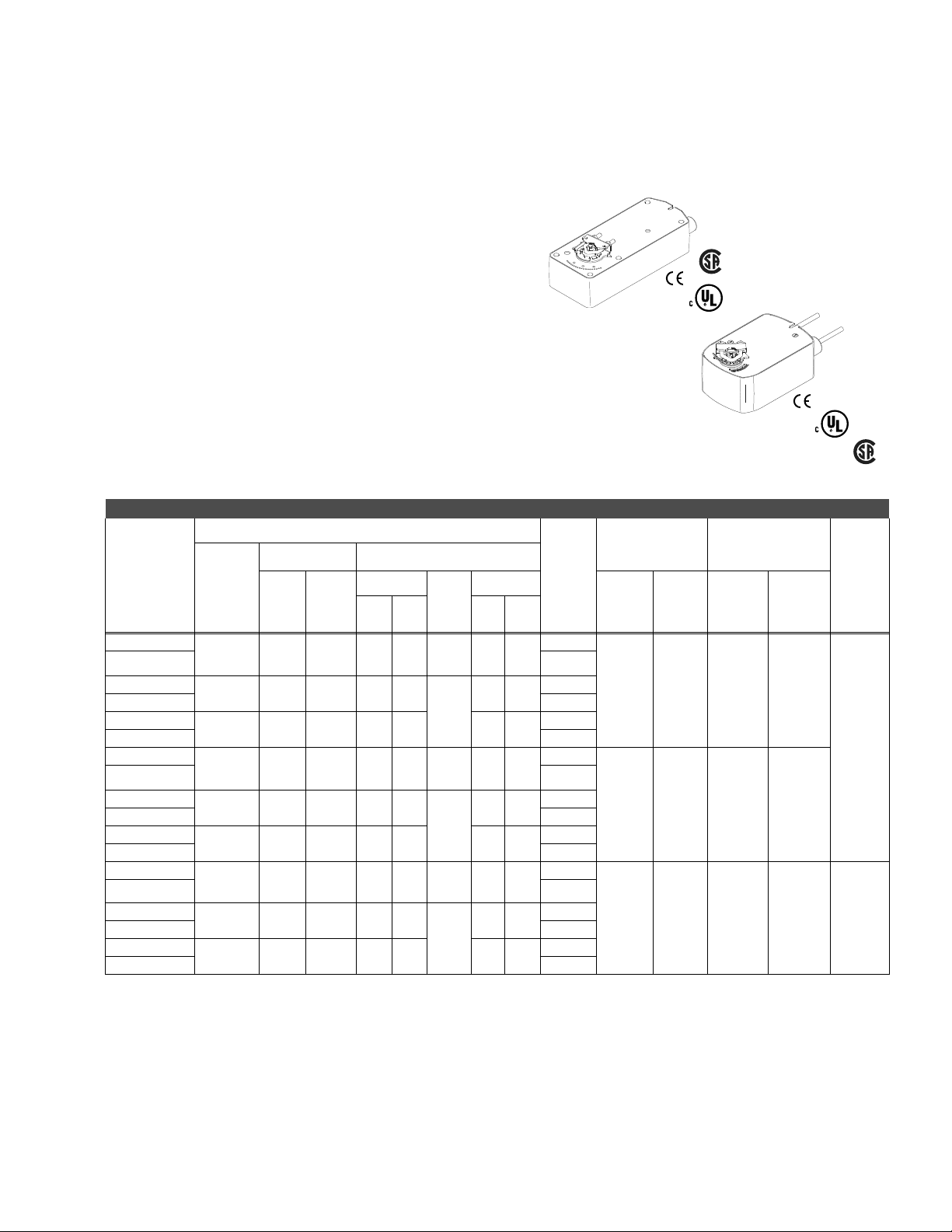
MA40-704x Series, MA41-707x Series, and MA41-715x Series
Spring Return DuraDrive® Two-Position Actuator
For spring return applications that require twoposition control of dampers and valves in HVAC
system.
Features:
• 35 lb.-in. (4 N-m), 60 lb.-in (7 N-m), 133 lb.-in (15 N-m).
• On-off control.
• Rugged die cast housings rated for NEMA 2/IP54.
• Overload protection throughout rotation.
• Optional built-in auxiliary switch to provide for interfacing or
signaling.
o
• Provides 95
of rotation.
• Visual position indicator provided.
• Rotation limiting available.
• MA41 series manual override.
Model Chart
Actuator Power Input
VA Watts
Part Number
MA41-7153 24 Vac
MA41-7153-502 Two
MA41-7150
MA41-7150-502 Two
MA41-7151
MA41-7151-502 Two
MA41-7073 24 Vac
MA41-7073-502 Two
MA41-7070
MA41-7070-502 Two
MA41-7071
MA41-7071-502 Two
MA40-7043 24 Vac
MA40-7043-501 One
MA40-7040
MA40-7040-501 One
MA40-7041
MA40-7041-501 One
a
Timing was measured with no load applied to the actuator.
b
De-rating is required at low temperatures.
c
One adjustable from 25 to 85o rotation and one set to operate @ 5o fixed.
d
One adjustable from 0 to 95o rotation (0 to 1 scale).
Voltage
± 20%
22-30 Vdc
120 Vac
± 10%
230 Vac
± 10%
± 20 %
22-30 Vdc
120 Vac
± 10%
230 Vac
± 10%
± 20%
22-30 Vdc
120 Vac
± 10%
230 Vac
± 10%
50 Hz 60 Hz
9.8 9.7 7.5 7.5 0.29 2.8 2.8
11.7 10.0 8.8 8.4
15.5 10.6 9.5 8.5 4.6 3.3
4.8 4.8 3.2 3.2 0.13 0.8 0.8
10.7 5.6 4.2 3.6
17.0 8.0 5.1 4.0 2.7 1.4
4.4 4.4 2.9 2.9 0.11 0.8 0.8
6.4 4.3 3.8 3.4
5.8 4.6 4.1 3.9 1.5 1.2
Running
50 Hz60
Hz
DC
Amps
—
—
—
Holding
50Hz60
5.0 3.6
2.0 1.2
1.6 1.2
Auxiliary
Switch
Hz
Timing in Seconds
Powered
No
c
No
c
No
c
No
c
No
c
No
c
No
d
No
d
No
d
Approximate
o
(21oC)
@ 70
Spring
Return
<190 <30 133 (15) 350 (40)
<80 <40 60 (7) 250 (28)
<50 <28 35 (4) 150 (17) No
US
Output Torque Rating
a
Minimum
lb-in (N-m)
Maximum
US
b
Manual
Override
Stall
Yes
79
Page 2

MA40-704x Series, MA41-707x Series, and MA41-715x Series
Specifications
Inputs
Control signal On-off SPST contacts or Triacs (500 mA).
Power Refer to Model Chart.
Connections
Outputs
Motor Type
Electrical
Mechanical
Environment
Ambient Temperature limits
Humidity 5 to 95% RH, non-condensing.
Locations
Dimensions
Agency Listings
UL
European Community EMC Directive (89/336/EEC). Low Voltage Directive (72/23/EEC).
CUL Canadian Standards C22.2 No. 24-93.
Australia
General Instructions Refer to F-26642.
3 ft. (0.9 m) long, appliance cable, 1/2 in. conduit connectors. For M20 Metric conduit, use AM-756
adaptor.
MA40-704x, MA41-707x: Brush.
MA41-715x: Brushless DC.
MA40-7043-501: One auxiliary switch available, SPDT 6A resistive @ 24 Vac, adjustable 0 to 95q (0 to
1 scale). UL listed,
MA40-7040-501 or MA40-7041-50: One auxiliary switch available, SPDT 6A resistive @ 240 Vac,
adjustable 0 to 95q (0 to 1 scale). UL listed, switch meets VDE requirements for 6 (1.5)A, 24 Vac.
MA41-715x-502 or MA41-707x-502: Two auxiliary switches available, SPDT 7A resistive @ 250 Vac,
one fixed @5 q and one adjustable 25 to 85
Vac.
Direction of rotation: CW or CCW rotation is available through reverse mounting.
Shaft clamp: Direct coupled using a through hole output hub.
MA40-704x: Up to 5/8 in. round, 1/2 in. square shafts.
MA41-71xx: Up to 3/4 in. round, 1/2 in. square shafts.
See Accessories for larger shaft options.
sition Indicator: MA40-704x: Visual indicator, 0 to 1 (0 is the spring return position).
Po
MA41-707x, MA41-715x: Pointer (-5 to 90°) and scale are provided for position indication (-5 is normal
or spring return position).
Shipping and storage: -40 to 160qF (-40 to 71qC).
Operating: -22 to 140qF (-30 to 60qC).
MA40-704x: NEMA 2 (IEC 1P54) no restrictions.
MA41-707x: NEMA 1 (IEC IP30), NEMA 2 (IEC IP54) with conduit in the down position.
MA41-715x: NEMA 1 (IEC IP30), NEMA 2 (IEC IP54) with conduit in the down position.
MA41-707x, MA41-715x: 10-1/2 H x 4 W x
MA40-704x: 6-51/64 H x 4 W x 3-1/2 D in. (68 x 100 x 89 mm).
UL-873, Underwriters Laboratories Listed (File #E9429 Category Temperature-Indicating and
Regulating Equipment).
This product meets requirements to bear the C-Tick mark according to the term
Communications Authority under the Radio Communications Act 1992.
switch meets VDE requirements for 6 (1.5)A, 24 Vac.
q. UL Listed, meets VDE requirements for 7 (2.5)A, 250
3-1/2 D in. (287 x 100 x 89 mm).
s specified by the
80
Page 3

MA40-704x Series, MA41-707x Series, and MA41-715x Series
Accessories
Model No. Description
MA41-707x, MA41-715x
abcd
AM-671
abcd
AM-672
a
AM-673
AM-674 Weather shield.
AM-675 Weather shield base.
AM-676 Universal shaft extension, approximately 9-1/2 in. long (242 mm) for use on 3/8 to 11/16 in. (10 to 17 mm)
AM-686 Position indicator.
AM-687 V-clamp for 1.05 in. round shafts.
AM-688 Replacement
AM-689 Rotation limiter.
AM-690 Crank arm.
AM-691 Crank arm.
AM-692 V-bolt.
ef
AM-693
AM-714 Weather shield.
AM-756 Metric conduit adaptor M20 x 1.5 to 1/2 in. NPT (two per package).
AM-758 Universal short “U” mounting bracket.
AM-759 Universal Long “U” mounting bracket.
AM-760 Universal slotted “L” mounting bracket.
AM-761 Replacement 7-inch anti-rotation bracket.
AM-762 Replacement 9-inch anti-rotation bracket.
AM-763 1/8 in ch hex crank for manual override.
AV-602 Vx-7xxx 1/2 to 2 in. valve linkage.
AV-607 Vx-9xxx 2-1/2 to 4 in. valve linkage.
Mounting bracket.
Mounting bracket.
Mounting bracket.
round shafts, 3/8 t o 9/16 in. square shafts. AM-753 clamps required).
universal clamp.
Crank arm kit.
MA40-704x
AM-673 Mounting bracket.
AM-674 Weather shield.
AM-675 Weather shield base.
AM-676 Universal shaft extension, approximately 9-1/2 in. long (242 mm) for use on 3/8 to 11/16 in. (10 to 17 mm)
AM-709 Position indicator and s
round shafts, 3/8 t o 9/16 in. square shafts. (AM-753 clamps required).
troke limiter.
AM-710 V-clamp for 3/4 in. round shafts.
AM-711 Crank arm adaptor kit.
e
AM-712
e
AM-713
AM-714 Weather shield
e
AM-715
Crank arm adaptor kit
Bracket.
Crank arm adaptor kit.
AM-717 Replacement universal clamp
AM-756 Metric conduit adapter
AM-761 Replacement 7-inch anti-rotation bracket.
AM-762 Replacement 9-inch anti-rotation bracket.
AV-605 Vx-7xxx 1/2 to 2 in. valve linkage.
a
Drill appropriate mounting holes where needed.
b
AM-693 crank arm kit required.
c
Cannot be used with Mx41-634x or Mx40-717x series actuators.
d
The large “C”-shaped clamps included in AM-693 crank arm kit are required for mounting the actuator. Drill appropriate mounting holes where needed.
e
Use the self-tapping screws and flat washers provided in kit to mount actuator.
f
AM-692 V-bolt kit required.
81
Page 4

MA40-704x Series, MA41-707x Series, and MA41-715x Series
Typical Applications
24 Vac Transformer
or 22-30 Vdc
Line
Volts
1
SPST Control Contact
120 Vac or
24 Vac
230 Vac
L1 N
L2 H
1
Voltage Wire 1 Wire 2
120 Vac White Black
230 Vac Light Blue Brown
Black
Red
Wire No. 1
Wire No. 2
Common
Hot (+DC)
Green/Yellow
Common
Hot
Green/Yellow
MA41-7153
MA41-7073
MA41-7153-502
MA41-7073-502
2
MA41-7150
MA41-7151
MA41-7070
MA41-7071
MA41-7150-502
MA41-7151-502
MA41-7070-502
MA41-7071-502
2
Optional Auxiliary
Switches
Orange
Violet
Yellow
Orange/White
Violet/White
Yellow/White
1 Provide overload protection and disconnect as required.
2 Actuators may be wired in parallel. All actuator black
wires are connected to the transformer common and all
red wires are connected to the hot lead. Power
consumption must be observed.
3 For end position indication, interlock control, fan startup,
etc., MA41-7153-502 and MA41-7073-502 models
incorporate two built-in auxiliary switches.
Com
N.C.
N.O.
Com
N.C.
N.O.
Aux Switches
MA41-7xxx-502
Aux Switch 1
25 to 85˚
Adjustable
Aux Switch 2
5˚ Fixed
Figure 1 Typical Wiring Diagram for 24, 120, or 240 Vac Basic and Double Auxiliary Switch Models.
120 Vac, or
230 Vac
1
L1 N
L2 H
Wire No. 1
Wire No. 2
Neutral
Hot
Green/Yellow
MA40-7040
MA40-7041
2
3
120 Vac, or
230 Vac
1
Auxiliary Switch 1
Figure 2 Typical Wiring Diagram for 120 Vac or 230 Vac Basic and Single Auxiliary Switch Models.
L1 N
L2 H
Wire No. 1
Wire No. 2
Orange
Violet
Yellow
Neutral
Hot
Green/Yellow
COM.
N.C.
N.O.
MA40-7040-501
MA40-7041-501
2
0 to 1 Scale
Adjustable
3
1 Provide overload protection and disconnect as
required.
2 Actuators may be wired in parallel. Power
consumption must be observed.
3 For end position indication, interlock control, fan
startup, etc., MA41-715x-502 and MA41-707x-502
models incorporate two built-in auxiliary switches.
See Specifications section for details.
Voltage Wire 1 Wire 2
120 Vac White Black
230 Vac Light Blue Brown
82
Page 5

717
ies
MA40-717x Series
Spring Return DuraDrive® Two-Position Actuator
For spring return applications that require two position
control of dampers and valves in HVAC systems.
Features:
• 150 lb.-in. (17 N-m) rated torque.
• On-off control.
• NEMA Type 4 housing (IEC IP56).
• Custom automatic current sensing motor control provides
extended reliability and repeatable timing.
• Direct coupled to the damper shaft with dual industrial hardened
universal mounting clamps.
-
• Accurate 93° travel digitally controlled.
x
• Integral position indication scale.
• Rugged die-ca
st housing.
• Oil immersed gear train provides continuous lubrication.
• Rated for operating temperature up to 140°F.
• Can be double mounted to accommodate high torque applications.
• 100% duty cycle.
US
LISTED
Model Chart
Damper Actuators
Actuator Power Input
a
Model No.
MA40-7173
c
Shaft Size
3/8 to 1/2 in.
round or
square
MA40-7171
a
Optional AM-753 damper shaft mounting clamps for 5/8 in. square or 3/4 to 1 in. round shafts.
b
De-rating required for spring return actuators at low temperatures.
c
The CE directive is not applicable to this model.
Stroke
93q± 1°
Voltage
24 Vac
± 20%
120 Vac
± 10%
240 Vac
± 10%
Running Holding
50/60 Hz 50/60 Hz
WVA W Powered
5.4 9.6 4.1
7.2 11.4 9.4
7.4 11.8 9.5
SPDT
Auxiliary
Switches
No <145 150 (17) 450 (51)MA40-7170
Valve Actuator plus LInkage.
Model No.
a
Linkage
(Included)
MA40-7173-200
MA40-7170-200 120 Vac ± 10% 7.2 11.4 9.4
AV-602
Voltage
50/60 Hz
Watts VA
24 Vac ± 20% 5.4 9.6 4.1
MA40-7171-200 240 Vac ± 10% 7.4 11.8 9.5
MA40-7173-220
MA40-7170-220 120 Vac ± 10% 7.2 11.4 9.4
AV-607
24 Vac ± 20% 5.4 9.6 4.1
MA40-7171-220 240 Vac ± 10% 7.4 11.8 9.5
MA40-7173-230
MA40-7170-230 120 Vac ± 10% 7.2 11.4 9.4
AV-609
24 Vac ± 20% 5.4 9.6 4.1
MA40-7171-230 240 Vac ± 10% 7.4 11.8 9.5
a
Refer to Valve Catalog, F-27384 for correct applications.
Approximate Timing
in Seconds @ 70°F
(21°C) with No Load
Running
Spring
Return
Output Torque Rating
Minimum
Holding
Watts
lb.-in. (N-m)
Maximum
b
SPDT Aux.
Switches
Stall
No
83
Page 6

MA40-717x Series
Specifications
Inputs
Control signal On-off SPST control contacts or Triacs (500 mA) rated.
Power Refer to Model Chart.
Connections 2 ft (61 cm) long appliance cable & 1/2 in. conduit connectors.
Outputs
Motor Type Brushless DC.
Mechanical
Environment
Ambient temperature limits
Humidity 5 to 95% RH, non-condensing.
Locations NEMA 1, NEMA 4 (IEC IP56) with customer supplied water tight connector.
Agency Listings
UL
European Community EMC Directive (89/336/EEC). Low Voltage Directive (72/23/EEC). Not applicable to MA40-7170.
CSA Canadian Standards C22.2 No. 4-93.
Australia
General Instructions Refer to F-26742.
Direction of rotation: CW or CCW rotation is available through reverse mounting.
Dual shaft clamps: Direct coupled using a through hole output hub.
Shipping and storage: -40 to 160q
F (-40 to 71qC).
Operating: -25 to 140qF (-32 to 60qC).
UL-873, Underwriters Laboratories Listed (File #9429 Category Temperature-Indicating and
Regulating Equipment).
This product meets requirements to bear the C-Tick mark according to the terms specified by the
Communications Authority under the Radio Communications Act 1992.
Accessories
Model No. Description
AM-674 Weather shield.
AM-676 Universal shaft extension, approximately 9-1/2 in. long (242 mm) for use on 3/8 to 11/16 in. (10 to 17 mm)
AM-751 Standard anti-rotation bracket 9 in. long x 13/16 in. wide (229 x 21 mm), included with actuator.
AM-752 Optional anti-rotation bracket 4 in. long x 1-11/16 in. wide (102 x 43 mm), for n
AM-753 Optional damper shaft mounting clamps for 5/8 in. square shaft, 3/4 in. and 1 in. round shafts (two per
AM-754 Standard universal mounting clamps for 3/8 to 1/2 in. (10 to 13 mm) round and square shafts, two included
AM-756 Metric conduit ada
AV-602 Vx-7xxx 1-1/2 to 2 in. valve linkage.
AV-607 Vx-9xxx 2-1/2 to 4 in. valve linkage.
round shafts, 3/8 to 9/16 in. square shaft s. (AM-753 clamps requ ired).
arrow spaces.
package).
with actuator.
ptor M20 x 1.5 to 1/2 in. NPT (two per package).
Typical Applications
GRDGreen/Yellow
24H
24G
MA40-717x
2
1 SPST or Triac Controller. Multiple MA40-7173
actuators may be powered by a single 24 Vac
transformer.
2 Unused conduit port must remain plugged with a
water tight pipe plug as shipped from factory to
maintain NEMA Type 4 or IP56 rating.
3 Ground wire may be Green on some models.
Voltage Wire Wire
4
(H) or L1) (G) or L2)
24 V Black Black/Blue
120 V Black White
240V Brown Light Blue
1
24 Vac
3
4
Black
Black/Blue
84
Figure 1 Typical Wiring Diagram for MA40-717x.
 Loading...