

Page 1
ies
-60xx
MS41-60xx Series
Non-Spring Return DuraDrive® Modulating Actuator
The DuraDrive direct coupled 24 Vac non-spring
return rotary electric actuators are designed for
modulating control of dampers.
Features:
• Compact, lightweight design.
• Self-adapting capability for maximum flexibility in damper
positioning.
• Manual override.
•5
q offset from 0q as shipped from factory.
• Offset and slope (zero and span) adjustment models
available.
• Independently adjustable dual auxiliary switches available.
• CUL and UL listed; CE certified.
• 0 to 10 Vdc feedback output.
0
9
45
0
9
US
LISTED
Model Chart
Damper Actuators.
Output Torque
Rating
Model No.
lb.-in.
(N-m)
Minimum 50 Hz 60 Hz
MS41-6043
MS41-6043-520 Yes None
MS41-6043-522 Yes Two
35 (4)
MS41-6043-502 None Two
MS41-6083
MS41-6083-520 Yes None
MS41-6083-522 Yes Two
70 (8)
MS41-6083-502 None Two
Valve Actuator/Linkages.
Model No.
a
Linkage
(Included)
MS41-6043-200
MS41-6043-202 Yes
MS41-6083-200 No
AV-603 24 Vac + 20% - 15% 3.3
MS41-6083-202 Yes
a Refer to Valve Catalog, F-27384 for correct applications.
Actuator Power Input
Voltage
Running
24 VAC
+20%-15%
VA
VA
Slope/Offset
Adjustable
(Zero Span)
SPDT
Auxiliary
Switches
None None
3.3
None None
Actuator Power Input 50/60 Hz.
Voltage
Approximate Timing in
Seconds @ 70°F (21°C)
with No Load
108 90
150 125
SPDT Auxiliary
VA
Running
Shaft Size
3/8" to 5/8"
dia.
1/4" to 1/2"
sq.
9/16" hex
Switches
No
175
Page 2

MS41-60xx Series
Specifications
Inputs
Control signal
Power
Connections 3 ft. (0.9 m) long, 18 AWG leads, plenum-rated.
Outputs
Electrical
Mechanical
Environment
Ambient temperature limits
Humidity 5 to 95% RH, non-condensing.
Locations NEMA 2, IP54 to EN60529.
Dimensions 5-7/16 H x 2-3/4 W x 2-3/8 D in. (138 x 70 x 60 mm ).
Agency Listings
UL UL-873, Underwriters Laboratories.
European Community
CUL Canadian Standards C22.2 No. 24-93.
General Instructions Refer to F-27214.
MS41-60x3: Proportional, 0 to 10 Vdc; input resistance 100K:Control signal adjustment available
with MS41-60x3-522 and MS41-60x3-522. Start point (offset): 0 and 50 Vdc (factory setting = 0 Vdc)
Span 2 to 30 Vdc.
24 Vac, +20%-15%, rated Class 2, Class III per EN60730.
MS41-6083: 24 Vac +20%/-10% at 90 to 130qF (32 to 55qC) ambient. Half wa
Output voltage: 0 to 10 Vdc.
Maximum output current: 1 mA.
MS41-60xx-502 auxiliary switch contact rating:
AC Rating: 24 Vac, 4A Resistive, 2A Inductive.
DC Rating: 12 to 30 Vdc, DC 2A.
Switching hysteresis: 2q
Switch range: Switch A: 0 to 90q range in 5q intervals; Recommended range usage: 0 to 45q; Factory
etting: 5qSwitch B: 0 to 90q range in 5q intervals; Recommended range usage: 45 to 90q; Factory
s
setting: 85q.
Timing: See Model Chart.
Output torque rating: MS41-6043, 35 lb-in. (4 N-m); MS41-6083, 70 lb-in. (8 N-m).
Stroke: Normal angle of rotation is 90q, limited to a maximum of 95q. Field adjustable to limit travel on
either end of stroke. MS41-60x3
Position indicator: Adjustable pointer is provided for position indication.
Shipping and Storage: -40 to 158qF (-40 to 70qC).
Operating: -25 to 130qF (-32 to 55qC).
EMC Directive (89/336/EEC). Emissions (EN50081-1). Immunity (EN50082-2).
-52x have adjustable start point and span.
ve device.
Accessories
Model No. Description
AM-726 Rotary to linear bracket.
AM-727 Rotary to linear crank arm adaptor.
AM-728 Conduit adaptor.
AM-729 3/8 in. shaft adapter.
AV-603 1/2 to 2 in. Vx-7xxx valve linkage.
176
Page 3
Typical Applications
1
Line
Volts
24 Vac
Transformer
Black
Red
Common (2)
Hot (1)
MS41-60xx Series
MS41-6043
Vdc Control Signal
Feedback Signal
2 to 10 Vdc
(-)
(+)
(-)
(+)
Grey
Pink
AI (8)
AO (9)
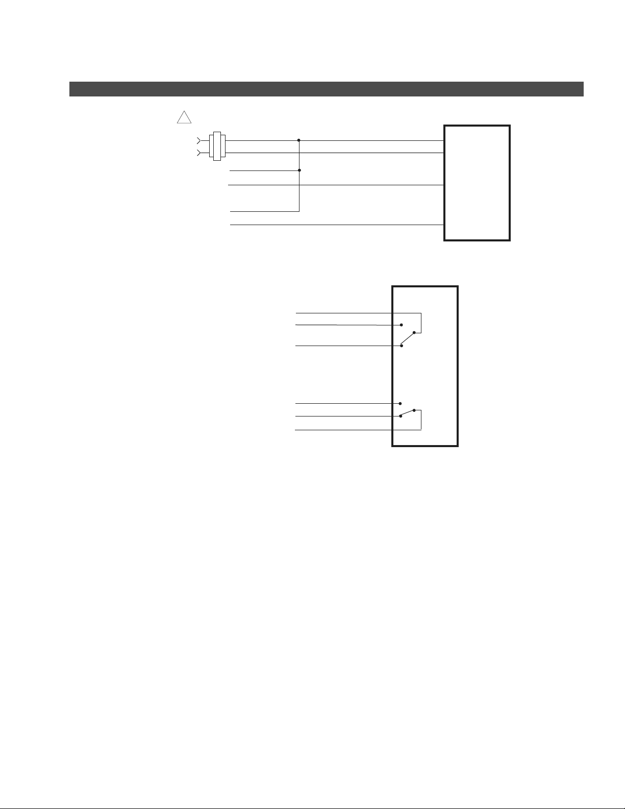
Figure 1 Typical Wiring for Proportional Control, 24 Vac, 0-10 Vdc Input.
Switch A
(COM)
S1
Black Leads
S3 (N.O.)
S2 (N.C.)
Switch B
S6 (N.O.)
S5 (N.C.)
S4 (COM)
0 -10 Vdc
2 - 10 Vdc
output
Figure 2 Typical Wiring for Auxiliary Switch Models MS41-60x3-502, -522, or -202.
177
Page 4

MS41-6153 Series
MS41-615
Non-Spring Return DuraDrive® Modulating Actuator
The DuraDrive direct-coupled, 24 Vac, non-spring
return electronic actuator is designed for
modulating control of building HVAC dampers.
Features:
• Synchronous motor technology with stall protection.
• Unique self-centering shaft coupling.
• Manual override.
• 133 lb-in (15 N-m) torque.
q offset from 0q as shipped from factory.
•5
• Mechanical range adjustment capabilities.
• Models with independently adjustable, dual auxiliary
switches available.
• Built-in 1/2-in. conduit connection.
• UL and cUL listed, CE certified.
• 0 to 10 (factory set) or 2 to 10 Vdc input field selectable.
• 0 to 10 Vdc feedback output.
US
LISTED
Series
Model Chart
Damper Actuators.
Power Input @ 50/60 Hz
Output
Model No.
MS41-6153
MS41-6153-502 2
Valve Actuator/Linkages.
Model No.
MS41-6153-200
MS41-6153-202 Yes
MS41-6153-220
MS41-6153-222 Yes
a Refer to Valve Catalog, F-27384 for correct applications.
Torque
Rating
lb.-in. (N-m)
133 lb-in
(15 N-m)
a
Voltage
24 Vac
± 20%
Linkage
(Included)
AV-605
AV-607
Running Holding
VA W VA W 50 Hz 60 Hz
5411
VA
Actuator Power Input 50/60 Hz.
Voltage
24 Vac ± 20% 5 4
SPDT
Auxiliary
Switches
No
VA
Running
Approximate Timing in
Seconds @ 70°F (21°C)
with No Load
150 125
SPDT Auxiliary
Watts
Shaft Size
1/4 to 3/4
in. dia.
1/4 to 1/2
in. sq.
Switches
No
No
Specifications
Inputs
178
Control signal 0 to 10 Vdc (factory set) or 2 to 10 Vdc input field selectable (max. 34 Vdc). Resistance: > 100K ohms.
Power
Connections 3 ft. (0.9 m) long, 18 AWG leads.
All 24 Vac circuits are Class 2. 24 Vac +20/-15% @ 50/60 Hz. Running VA: 5 @ 4 W, Holding VA: 1.2 @
1 W. Half wave device.
Page 5

Specifications (Continued)
Outputs
Position output signal wires 9 and 2.
Output voltage: 0 to 10 Vdc.
Maximum output current: ± 1 mA
Dual auxiliary switches available on MS41-6153-502.
Switch contact rating: 6A resistive, 2A inductive.
Switch voltage: 24 Vac.
Electrical
Mechanical
Environment
Ambient temperature limits
Humidity 5 to 95% RH, non-condensing.
Locations NEMA Type 1, IP54 according to EN 60 529.
Dimensions 8-3/8 H x 3-1/4 W x 2-2/3 D in. (213 x 83 x 68 mm).
Agency Listings
UL UL-873, Underwriters Laboratories. UL Listed to UL 60730.
European Community EMC Directive (89/336/EEC). Emissions (EN50081-1). Immunity (EN61000-6-2).
CUL Canadian Standards C22.2 No. 24-93.
General Instructions Refer to F-27215.
Switching hysteresis: 2
Switch range: Switch A: 0 to 90q range in 5q intervals; Recommended range usage: 0 to 45q; Factory
etting: 5qSwitch B: 0 to 90q range in 5q intervals; Recommended range usage: 45 to 90q; Factory
s
setting: 85q.
Timing: 150 seconds @ 50 Hz. 125 seconds @ 60 Hz.
Output torque rating: 133 lb-in. (15 N-m).
Stroke: Normal angle of rotation is 90q, limited to a maximum of 95q. Field adjustable to limit travel on
either end of stroke.
Position indicator: Adjus
Operation: -25 to 130qF (-32 to 55qC).
Storage and transport: -40 to 158qF (-40 to 70qC).
table pointer is provided for position indication.
MS41-6153 Series
Accessories
Model No. Description
AM-674 Weather shield.
AM-675 Mounting base for weather shield.
AM-703 Span adjustment module.
AM-704 Pulse to 2 to 10 Vdc converter.
AM-705 Remote positioner surface mount for 0 to 10 Vdc control.
AM-706 Remote positioner flush mount for 0 to 10 Vdc control.
AM-726 Linear conversion kit with mounting bracket.
AM-727 Linear conversion kit.
179
Page 6

MS41-6153 Series
Typical Applications
1
Line
Volts
24 Vac
Transformer
Black
Red
Common (2)
Hot (1)
MS41-6153
Input Control Signal
Feedback Signal
2 to 10 Vdc
(-)
(+)
(-)
(+)
Gray
Pink
AI (8)
AO (9)
Figure 1 Typical Wiring for Proportional Control 24 Vac, 0-10 Vdc Input Standard.
Switch A
Gray/Pink
Gray/Blue
Gray/Red
Black/Pink
Black/Blue
Black/Red
(N.O.)
S3
S2 (N.C.)
S1 (COM)
S6 (N.O.)
S5 (N.C.)
S4 (COM)
Switch B
180
Figure 2 Typical Wiring for Auxiliary Switch Models MS41-6153-502, -505, or -222.
Page 7

634
ies
MS41-634x Series
Non-Spring Return DuraDrive® Proportional Actuator
For non-spring return applications that require
proportional modulation control of dampers and
valves in HVAC systems.
Features:
• Direct mount to round or square damper shaft.
• 300 lb.-in (34 N-m) rated torque.
• Overload protection throughout rotation.
• Oil immersed gear train provides continuous lubrication.
• NEMA 4 housing (IEC IP56).
• Manual override to allow positioning for installation and
manual operation.
-
• Automatic current sensing motor control provides extended
x
reliability and repeatable timing.
• Proportional control compatible with 2 to 10 Vdc or 4 to
20 mAdc with integrated resistor.
US
LISTED
Model Chart
Damper Actuators.
Output Torque Rating
Model No.
MS41-6343
MS41-6340
MS41-6341 240 Vac ± 10%
a
Valve Actuator/Linkages.
MS41-6043-200 AV-609 24 Vac ± 20% 8 10 N/A No
a
a
The CE directive is not applicable to this model.
Model No.
AV-609: Use with 5 and 6 in. VB-9xxx and 6 in. VB-8xxx globe valves.
lb.-in. (N-m)
Maximum
Stall
300 (34) 600 (68)
Linkage
(Included)
Voltage VA
24 Vac ± 20%
120 Vac ± 10%
a
Power Input @ 50/60 Hz
Watts
Running HoldingMinimum
810NANo <145
Actuator Power Input 50/60 Hz.
Voltage VA
SPDT
Auxiliary
Switches
Running Holding
Approximate
Timing in
Seconds @ 70°F
(21°C) with No
Load
Watts
SPDT Auxiliary
Switches
Specifications
Inputs
Control signal Proportional, 2 to 10 Vdc or 4 to 20 mAdc with intergral 500 ohm resistor.
Power Refer to Model Chart.
Connections 2 ft. (0.6 m) appliance cable. 1/2 in. conduit connectors. For M20 metric conduit, use AM-756 adaptor.
Outputs
Motor Type Brushless DC.
Direction of rotation: CW or CCW rotation is available through reverse mounting.
Mechanical
Dual shaft clamp: Direct coupled using a through hole o
Position indicator: Pointer and scale.
utput hub for 3/8 to 1/2 in. round included.
Shaft Size
1/2 to 1 in.
diameter
1/2 to 5/8 in.
square
187
Page 8

MS41-634x Series
Specifications (Continued)
Environment
Temperature limits
Humidity 5 to 95% RH, non-condensing.
Locations NEMA 1, NEMA 4 (IEC IP56) with customer supplied water tight connectors.
Dimensions 10-27/32 H x 4 W x 4 D in. (275 x 102 x 102 mm).
Agency Listings
UL
European Community EMC Directive (89/336/EEC). Low Voltage Directive (72/23/EEC).
CSA Ca
Australia
General Instructions Refer to F-26745.
Accessories
Model No. Description
AM-676 Universal shaft extension, approximately 9-1/2 in. long (242 mm) for use on 3/8 to 11/16 in. (10 to 17 mm) round shafts, 3/8 to
AM-703 Span adjustment module mA/Vdc input to 2 to 10 Vdc output.
AM-704 Modulating interface pulse to 2 to 10 Vdc control.
AM-705 Positioner for 0 to 10 Vdc control.
AM-706 Positioner for 0 to 10 Vdc control.
AM-751 Standard anti-rotation
AM-752 Optional anti-rotation bracket 4 in. long x 1-11/16 in. wide (102 x 43 mm), for narrow spaces.
AM-753 Damper shaft mounting clamps for 5/8 in. square shaft, 3 /4 in. and 1 in. round shafts (two pe r package).
AM-754 Standard universal mounting clamps for 3/8 in. to 1/2in. (10 to 13 mm) ro
AM-755 Manual override crank.
AM-756 Metric conduit adaptor M20 x 1.5 to 1/2 in. NPT (two per package).
AV-609 5 and 6 in. Vx-9xxx valve linkage or 6 in VX-8000.
Shipping and Storage: -40 to 160qF (-40 to 71qC) ambient.
Operating: -25 to 140qF (-32 to 60qC).
UL-873, Underwriters Laboratories Listed (File #E9429 category: Temperature-Indicating and
Regulating Equipment.)
nadian Standards C22.2 No. 24-93.
This product meets requirements to bear the C-Tick mark according to the terms specified by the
Communications Authority under the Radio Communications Act 1992.
9/16 in. square shafts. (AM-753 clamps required).
bracket 9 in. long x 13 /16 in. wide (229 x 21 mm), included with actuator.
und and square shaft s, two included with actuator.
Typical Applications
1 Unused conduit port must remain plugged with
a water tight pipe plug as shipped from factory
to maintain NEMA Type 4 or IP56 rating.
2 Ground wire may be Green on some models.
Figure 1 Typical Wiring Diagram for 2 to 10 Vdc Controller with a 24 Vac Actuator
1 Unused conduit port must remain
plugged with a water tight pipe plug as
shipped from factory to maintain NEMA
Type 4 or IP56 rating.
2 Ground wire may be Green on some
models.
Figure 2 Typical Wiring Diagram for 4 to 20 mA Controller with a 24 Vac Actuator
2 to 10 Vdc
Controller
+
-
24 Vac
Unused
(wire nut)
2
White
Red
Black
Black
Black/Blue
+ IN
500Ω
COM
24G
GRDGreen/Yellow
MS41-6343
1
24H
(See Power Wiring Identification for 120 or 240 V Power).
4 to 20 mA
+
24 Vac
White
-
Black/Blue
2
Red
Black
Black
+IN
500Ω
COM
GRDGreen/Yellow
MS41-6343
1
24H
24G
(See Power Wiring Identification for 120 or 240 V Power).
Power Wire Identification
Voltage Designation Wire Color
24 L1 Black
L2 Black/Blue
120 L1 Black
L2 White
240 L1 Brown
L2 Light Blue
Power Wire Identification
Voltage Designation Wire Color
24 L1 Black
L2 Black/Blue
120 L1 Black
L2 White
240 L1 Brown
L2 Light Blue
188
 Loading...