

Page 1
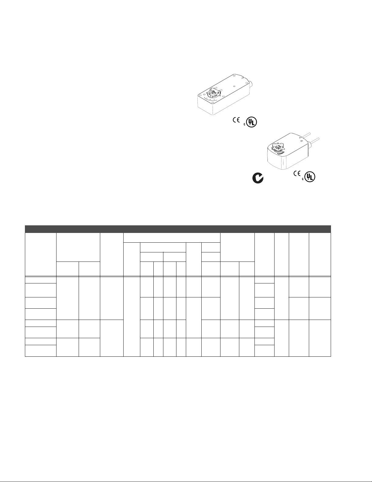
MS40-7043, MS41-7073, MS41-7153
MS40-704
Spring Return DuraDrive® Proportional Actuator
For spring return applications that require
proportional modulation control of dampers and
valves in HVAC systems.
Features:
• Proportional models controlled by 6-9 Vdc, 2-10 Vdc or
4-20 mA with the addition of a 500 ohm resistor.
• 35 lb.-in. (4 N-m), 60 lb.-in (7 N-m), 133 lb.-in (15 N-m).
• Direct mount to round or square damper shaft.
• Overload protection throughout rotation.
• True mechanical clockwise or counterclockwise spring
return operation for positive close-off in airtight
applications.
• Visual position indicator.
• Direct a
cting or reverse acting control mode available on
proportional models.
• Rotation limiting available.
• Rugged die-cast housing.
• MS40-7043: plenum rated cables.
• MS41-7xxx equipped with manual override.
US
MS41-707
MS41-715
US
Model Chart
Output Torque
Rating
Model No.
MS40-7043
MS40-7043-
c
501
MS40-7043MP
MS40-7043MP5
MS41-7073
MS41-7073502
MS41-7153
MS41-7153502
a
Timing was measured with no load applied to the actuator.
b
De-rating required for spring return actuators at low temperatures.
c
With plenum-rated cable.
d
One adjustable from 0 to 95q rotation (0 to 1 scale).
e
One adjustable from 25 to 85q rotation and on e set to operate @ 5q fixed.
lb.-in. (N-m)
Maximum
Minimum
c
b
Stall
35 (4) 120 (14)
60 (7) 160 (18)
133 (15) 300 (34) 9.8 7.4 9.7 7.4 .28 2.9 <190 <30
Stroke
95q ± 5q
maximum,
adjustable
from 40 to
95q with
mechanical
stop
95q ± 5q
maximum,
adjustable
from 30 to
95q with
AM-689
rotation
limiter
Voltage
24 Vac
± 20%
22-30
Vdc
50 Hz 60 Hz 50/60 Hz
VA W VA W W Powered
5.6 4.2 5.6 4.2 .15 2.4
6.65.06.65.0
5.8 4.6 5.8 4.6 2.3 <195 <30
Power Input
Running
DC
Amps
.17
Holding
3.2
Approximate
Timing in
Seconds @ 70°F
a
(21°C)
Spring
Return
<130 <25
SPDT
Auxiliary
Switches
No
d
One
No
d
One
No
e
Two
No
e
Two
Shaft
Size
5/8 in.
dia.
1/2 in.
sq.
3/4 in.
dia.
1/2 in.
sq.
Auxiliary
Power
Supply
None
+20 Vdc
25mA
max
None
Input
2-10 Vdc
or
4-20 mA
w/500 :
6-9 Vdc
2-10 Vdc
or
4-20 mA
w/500 :
166
Page 2

MS40-7043, MS41-7073, MS41-7153
Specifications
Inputs
Control signal Proportional, 6 to 9 Vdc, 2 to 10 Vdc, or 4 to 20 mA with 500 ohm resistor.
Power All 24 Vac circuits are Class 2. Refer to Model Chart for AC and DC ratings. Half wave device.
MS41-7073, MS41-7153: 3 ft. (0.9 m) long, appliance cables, 1/2 in. conduit connectors. For M20
Connections
Outputs
Motor Type Brushless DC.
Electrical
Mechanical
Environment
Temperature limits
Humidity 5 to 95% RH, non-condensing.
Locations NEMA 1, NEMA 2 (IEC IP54) with conduit in the down position.
Agency Listings
UL
European Community EMC Directive (89/336/EEC). Low Voltage Directive (72/23/EEC).
CSA Canadian Standards C22.2 No. 4-93.
Australia
General Instructions Refer to F-26645.
metric conduit, use AM-756 adaptor. MS40-7043: 3 ft. (0.9 m) long, plenum-rated cables, 1/2 in.
conduit connectors. For M20 metric conduit, use AM-756 adaptor. MS40-7043: 3 ft. (0.9 mm ) plen
rated cable.
Internal Power Supply: 20 Vdc, 25 mA.
Control Mode: Switch provided for selection of direct acting or reverse acting control mode.
Position Indicator: MS40-7043: Visual indicator, 0 to 1 (0 is the spring return position).
MS41-7073, MS41-7153: Pointer (-5 to 90°) and scale are provided for position indication (-5 is normal
or spring return position).
Direction of rotation: CW or CCW rotation is available through reversible mo
Damper shaft clamp: Direct coupled using a through hole output hub.
Shipping and storage: -40 to 160qF (-40 to 71qC) ambient.
Operating: -22 to 140qF (-30 to 60qC).
UL-873, Underwriters Laboratories Listed (File #9429 Category: Temperature-Indicating and
ating Equipment).
Regul
This product meets requirements to bear the C-Tick mark according to the terms specified by the
Communications Authority under the Radio Communications Act 1992.
unting.
um
167
Page 3

MS40-7043, MS41-7073, MS41-7153
Accessories
Model No. Description
MS40-7043, MS41-7073, MS41-7153
a
AM-673
AM-674 Weather shield.
AM-675 Weather shield base.
AM-676 Universal shaft extension, approximately 9-1/2” long (242 mm) for use on 3/8” to 11/16” (10 to 17 mm) round
AM-703 Span adjustment.
AM-704 Modulating interface.
AM-705 Positioner.
AM-706 Positioner.
AM-707 Digital indication.
AM-708 500 ohm resistor.
AM-756 Metric conduit adaptor M20 x 1.5 to 1/2” NPT (two per package).
AM-714 Weather shield.
f
AM-715
AM-762 Replacement 9-inch anti-rotation bracket
MS41-7073, MS41-7153
abcd
AM-671
abcd
AM-672
AM-686 Position indicator.
AM-687 V-clamp.
AM-688 Replacement universal clamp
AM-689 Rotation limiter.
AM-690 Crank arm.
AM-691 Crank arm.
AM-692 V-bolt.
ef
AM-693
AM-758 Universal short “U” mounting bracket
AM-759 Universal long “U” mounting bracket
AM-760 Universal slotted “L” mounting bracket
VA-602 Vx-7xxx 1 to 2 in. valve linkage.
VA-607 Vx-9xxx 2-1/2 to 4 in. valve linkage.
MS40-7043
AM-709 Position indicator and stroke limiter.
AM-710 V-clamp.
AM-711 Crank arm adaptor kit.
f
AM-712
f
AM-713
AM-717 Replacement universal clamp
AM-761 Replacement 7-inch anti-rotation bracket
AV-605 Vx-7xxx 1/2 to 2 in. valve linkage.
a
Drill appropriate mounting holes where needed.
b
AM-693 crank arm kit required.
c
Cannot be used with Mx41-634x or Mx40-717x series actuators.
d
The large “C”-shaped clamps included in AM-693 crank arm kit are required for mounting the actuator.
e
AM-692 V-bolt kit required.
f
Use the self-tapping screws and flat washers provided in kit to mount actuator.
Mounting bracket.
shafts, 3/8” to 9/16” square shafts. (AM-753 clamps required).
Crank arm adaptor kit.
Mounting bracket.
Mounting bracket.
Crank arm kit.
Crank arm adaptor kit.
Bracket .
168
Page 4

Typical Applications
24 Vac
1
Transformer
Line
Volts
Control Signal
2 to 10 Vdc
(-)
(+)
Figure 1 2 to 10 Vdc Control of MS40-7043 and MS40-7043-501 Actuator.
24 Vac
1
Transformer
Line
Volts
Control Signal
4 to 20 mA
Feedback Signal
2 to 10 Vdc
(-)
(+)
(-)
(+)
4
To other
actuators
6
Ω
500 Ω
2
Grey
Black
Red
Yellow/Black
2
5
Yellow/Black
Grey
Black
Red
Blue
MS40-7043, MS41-7073, MS41-7153
Common
Common
Hot
AI
Green/Yellow
Common
Common
Hot
AI
AO
Green/Yellow
MS40-7043
MS40-7043-501
L R
MS40-7043
MS40-7043-501
3
L R
4
1 Provide overload protection
and disconnect as required.
2 Actuators may be connected
in parallel. Power
consumption and input
impedance must be observed.
1 Provide overload protection and
disconnect as required.
2 For unison operation in 4 to 20 mA
applications, actuators may be
wired in series and mounted on
separate shafts. Also, up to four
actuators, mounted on separate
shafts may be wired in parallel.
With four actuators wired to one
500 ohm resistor, a +2%
control signal may be required.
Power consumption and input
impedance limits must be
observed. Actuator input
impedance is 80 kohm.
3 For end position indication, interlock
control, fan startup, etc., MS407043-501 model incorporates one
built-in auxiliary switch.
4 To reverse actuator rotation, use
the reversing switch.
5 A field supplied 500 ohm resistor
(AM-708) is required between the
gray and yellow/black leads to
convert the 4 to 20 mAdc control
signal to 2 to 10 Vdc.
6 Only connect common to negative
(-) leg of control circuits.
shift of the
Figure 2 4 to 20 mA Control of MS40-7043 and MS40-7043-501 with 2 to 10 Vdc Feedback Control.
169
Page 5

MS40-7043, MS41-7073, MS41-7153
24 Vac
1
Transformer
Line
Volts
Control Signal
4 to 20 mA
Auxiliary Power
+20 Vdc
25 mA
(-)
(+)
(-)
(+)
2
Figure 3 6 to 9 Vdc Proportional Control with 20 Vdc Power Output.
Grey
Black
Red
Yellow/Black
Blue
Common
Common
Hot (DC)
AI
AO
Green/Yellow
MS40-7043-MP
MS40-7043-MP5
L R
3
1 Provide overload protection and
disconnect as required.
2 For unison operation in 4 to 20 mA
applications, actuators may be
wired in series and mounted on
separate shafts. Also, up to four
actuators, mounted on separate
shafts may be wired in parallel.
With four actuators wired to one
500 ohm resistor, a +2% shift of the
control signal may be required.
Power consumption and input
impedance limits must be
observed. Actuator input
impedance is 80 kohm.
3 To reverse actuator rotation, use
the reversing switch.
Orange
Violet
Yellow
Orange/White
Violet/White
Yellow/White
Com
NC
NO
Com
NC
NO
1 For end position indication, interlock control
fan startup, etc., MS40-7XX3-50X models
incorporate one or two built-in auxiliary
A
1
B
switches. See Specifications section
for details.
Model # Switch Switch Type
MS40-7153-502
MS40-7073-502
MS40-7043-501
A Adjustable, 25° - 85°
B Fixed at 5°
A Adjustable, 0 - 1 scale
BNone
Figure 4 Optional Auxiliary Switches.
170
Page 6

MS40-7043, MS41-7073, MS41-7153
Figure 5 Typical Wiring Diagrams for Proportional Control 24 Vac Basic and Double Auxiliary Switch Models.
171
Page 7

MS40-717x Series
MS40-717x
Spring Return DuraDrive® Proportional Actuator
For spring return applications that require
proportional modulation control of dampers and
valves in HVAC systems.
Features:
• 150 lb.-in. (17 N-m) rated torque.
• Direct mount to round or square damper shaft.
• Overload protection throughout rotation.
• True mechanical clockwise or counterclockwise spring
return operation for positive close-off in airtight
applications.
• Oil immersed gear train provides continuous lubrication.
• NEMA 4 housing (IEC IP56).
• Automatic current sen
reliability and repeatable timing.
• Visual position indicator.
• Provide proportional control compatible with 2 to 10 Vdc or
4 to 20 mAdc with intergrated resistor.
sing motor control provides extended
LISTED
US
Series
Model Chart
Damper Actuators.
Actuator Power Input 50/60 Hz.
Output Torque Rating
Model No.
MS40-7173
MS40-7170
MS40-7171 240 Vac ± 10% 7.2 11.8 10.1
a
De-rating required for spring return actuators at low temperatures.
b
The CE directive is not applicable to this mod el.
Valve Actuator/Linkages.
MS40-7173-200
MS40-7170-200
MS40-7171-200 240 Vac ± 10% 7.2 11.8 10.1
MS40-7173-220
MS40-7170-220 120 Vac ± 10% 7.1 11.1 9.1
MS40-7171-220 240 Vac ± 10% 7.2 11.8 10.1
a
AV-602: Use with 1-1/4 to 2 in. globe valves. AV-607: Use with 2-1/2 to 4 in. globe valves.
b
The CE directive is not applicable to this mo del.
b
Model No.
lb.-in. (N-m)
Maximum
Minimum
150 (17) 450 (51)
b
a
Stall
Linkage
(Included)
AV-602
AV-607
Voltage Watts Stroke
24 Vac ± 20% 7.1
120 Vac ± 10% 7.1 11.1 9.1
a
Voltage Watts
24 Vac ± 20% 7.1 9.4 5.4
120 Vac ± 10% 7.1 11.1 9.1
24 Vac ± 20% 7.1 9.4 5.4
93°
± 1°
Actuator Power Input 50/60 Hz.
VA
Running Holding Powered
9.4 5.4
Running Holding
SPDT
Auxiliary
Switches
No <145
VA
Approximate
Timing in
Seconds @ 70°F
(21°C) with No
Load
Spring
Return
SPDT Auxiliary
Shaft Size
1.05 in. dia.
5/8 in. sq.
Switches
No
172
Page 8

MS40-717x Series
Specifications
Inputs
Control signal Proportional, 2 to 10 Vdc or 4 to 20 mAdc with integral 500 ohm resistor.
Power Refer to Model Chart.
Connections 2 ft. (0.6 m) appliance cables, 1/2 in. conduit connector. For M20 metric conduit, use AM-756 adaptor.
Outputs
Motor Type Brushless DC.
Direction of rotation: CW or CCW rotation is available through reverse mounting.
Dual shaft clamp: Direct coupled using a through hole output hub.
Mechanical
Position indicator: Pointer and sca
return position).
Stroke: 93q ± 1q
Environment
Ambient Temperature limits
Shipping and storage: -40 to 160qF (-40 to 71qC).
Operating: -25 to 140qF (-32 to 60qC).
Humidity 5 to 95% RH, non-condensing.
Locations NEMA 1, NEMA 4 (IEC IP56) with customer supplied water tight connector.
Dimensions 10-27/32 H x 4 W x 4 D in. (275 x 102 x 102 mm).
Agency Listings
UL
UL-873, Underwriters Laboratories Listed (File #E9429 Category: Temperature-Indicating and
Regulating Equipment).
European Community EMC Directive (89/336/EEC). Low Voltage Directive (72/23/EEC).
CSA Canadian Standards C22.2 No. 4-93.
Australia
This product meets requirements to bear the C-Tick mark according to the terms specified by the
Communications Authority under the Radio Communications Act 1992.
General Instructions Refer to F-26748 and F-27384.
le are provided for position indication (0q is the normal, or spring
Accessories
Model No. Description
AM-674 Weather shield.
AM-676 Universal shaft extension, approximately 9-1/2 in. long (242 mm) for use on 3/8 to 11/16 in. (10 to 17 mm)
AM-703 Span adjustment.
AM-704 Modulating interface.
AM-705 Posit ioner.
AM-706 Posit ioner.
AM-707 Digital indication.
AM-751 Standard anti-rotation b
AM-752 Optional anti-rotation bracket 4 in. long x 1-11/16 in. wide (102 x 43 mm), for narrow spaces.
AM-753 Damper shaft mounting clamps for 5/8 in. square shaft, 3/4 in. and 1 in. round shafts (two per package).
AM-754 Standard universal mounting clamps for 3/8 to 1/2 in. (10 to 13 mm) rou
AV-602 Vx-7xxx 1/2 to 2 in. valve linkage.
AV-607 Vx-9xxx 2-1/2 to 4 in. valve linkage.
M-756 Metric conduit adaptor M20 x 1.5 to 1/2 in. NPT (two per package).
round shafts, 3/8 to 9/16 in. square shafts. AM-753 clamps required).
racket 9 in. long x 13/16 in. wide (229 x 21 mm), included with actuator.
with actuator.
nd and square shafts, two included
173
Page 9

MS40-717x Series
Typical Applications
1 Unused conduit port must remain
plugged with a water tight pipe plug as
shipped from factory to maintain NEMA
Type 4 or IP56 rating.
2 Ground wire may be Green on some models.
3 See "Power and Control Wiring Color Codes"
for L1 and L2 wire colors.
Figure 1 Typical MS40-7170 2 to 10 Vdc Wiring Diagram (120 Vac).
1 Unused conduit port must remain
plugged with a water tight pipe plug as
shipped from factory to maintain NEMA
Type 4 or IP56 rating.
2 Ground wire may be Green on some models.
3 See "Power and Control Wiring Color Codes"
for L1 and L2 wire colors.
2 to 10 Vdc
4 to 20 mA
+
-
+
-
120 Vac
120 Vac
Unused
(wire nut)
2
2
White
Black
Black
White
White
Red
Black
Black
White
Red
3
3
500:
COM
+IN
500:
COM
GRDGreen/Yellow
+IN
GRDGreen/Yellow
L1
L2
MS40-7170
1
L1
L2
MS40-7170
1
Figure 2 Typical MS40-7170 4 to 20 mA Wiring Diagram (120 Vac).
Power and Control Wiring Color Codes.
Model Lead Color Voltage
MS40-7171
MS40-7173
174
L1
L2
L1
L2
Brown
Light Blue
Black
Black/Blue
240V
240V
24 V H
24 V G
 Loading...