

Page 1
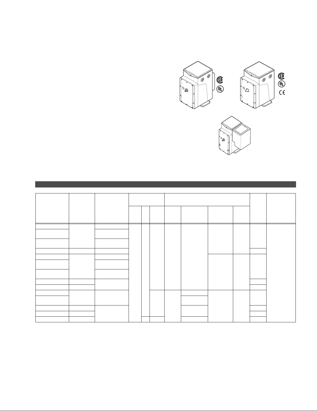
MP-3xx Series, MP-4xx Series, MP-2xxx Series, and MP-4xxx Series
Reversible and Proportional Electric Actuators
The MP Series Actuators are used for two-position,
floating, and proportional control of dampers,
valves, and program switches in heating,
ventilation, and air conditioning applications or
similar applications.
P-3xx
eries,
P-4xx
eries,
P-2xxx
eries,
d MP-
xx
eries
Features:
• Proportional actuators with built-in feedback
potentiometers.
• Spring return and non-spring return models available.
Typical Spring Return
Typical Non-Spring Return
• 24 Vac, 120 Vac, and 240 Vac models are available.
• Die cast housings with four 1/2 in. conduit openings.
• Oil-immersed motor and gear train.
Typical -6XX Suffix
(CP-8301-XXX Installed,
CP-9301-XXX or
CP-9302-91X Installed)
Typical -691 or -692 Suffix
(CP-9301-XXX or
CP-9302-91X Installed)
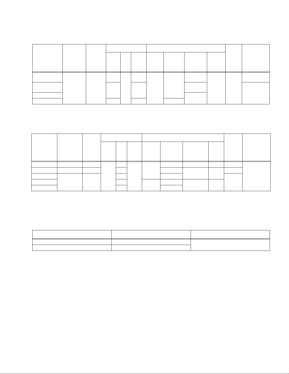
Model Chart
MP-3xx Series.
Solid State
Model No. Application
MP-361
MP-361-600
MP-361-691
MP-367 Sequencing — SPST
MP-371
MP-371-600
MP-371-691
MP-377 Sequencing
MP-379 Five position None
MP-381
MP-382
MP-387 Sequencing
MP-389 Five position None
MP5-381 Proportional 50 2.5 156 SPDT
a
Units with a “-2” suffix, e.g. MP-xxxx-xxx-2-x, include a built-in transformer (used for Microtherm or with AE-504) with secondary loads
wired externally to terminals seven and eight of the actuator. Red (24 Vac) to terminal eight and Blue (12 Vac) to terminal seven. When
these actuators are used with controllers other than Microtherm or AE-504, disconnect the Red and Blue leads and tape off. Note: Models
prior to “-2” suffix had transformer wired directly to potentiometer. To di
disconnect, and tape the transformer leads.
b
Rotation adjustable 45 to 320q. Caution: On actuators with proportional input signals changing the rotation will affect the control, since
the internal feedback potentiometer’s travel is fixed.
c
Integral solid state drive CP-8301 accepts 6-9 Vdc voltage with 20 Vdc power supply included.
d
Integral solid state drive CP-9301 accepts 6-9 Vdc voltage.
c
Proportional
d
c
Proportional
d
Proportional Available
Drive
CP-8301-xxx
CP-9301
CP-9302
Available
CP-8301-024
Included
CP-9301
Included
Available
CP-8301-024
Included
CP-9301
Included
—
Available
Power
Requirements
Volts Hz Amps
2.5
60
24
2.2
Output Shaft
No
Aux.
Switch
SPDT
SPDT
SPST
SPDT
SPST
Torque
lb.-in.
(N-m)
50
(5.6)
220
(24.9)
sconnect the transformer, remove the back plate of the actuator,
Timing
Seconds
(No Load)
90
130
130 to 1300
(Adj.)
130
Degrees of
Rotation
180
b
(Adj.
)
180
(non Adj.)
180
b
(Adj.
)
Spring
Return
CW
CCW
Built-in
Transformer
a
137
Page 2

MP-3xx Series, MP-4xx Series, MP-2xxx Series, and MP-4xxx Series
MP-4xx Series
Solid
State
Model No. Application
Drive
CP-9301
CP-9302
MP-421
MP-422
MP-423 13
MP-424
MP-451
Proportional Available
MP-452
MP-453 40
MP-454
CP-8301-
MP-461-600
refer to
footnote
c
120
Included
MR-461-691 CP-9301
MP-465 Proportional Available
MP-470
Five
position
—
CP-8301-
MP-471-600
MP-471-691
refer to
footnote
c
120
Included
CP-9301
Included
MP-475 Proportional Available
MP-480
Five
position
—
MP-481 Proportional Available SPDT
CP-8301-
c
120
Included
CP-9301
Included
MP-481-600
MP-481-691
c
refer to
footnote
MP-483
MP-485 130
MP-486
Proportional Available
MP-495 0.95
MP5-483 — 50 0.5
a
Units with a “-2” suffix, e.g. MP-xxxx-xxx-2-x, include a built-in transformer (used for Microtherm or with AE-504) with secondary loads wired externally to
terminals seven and eight of the actuator. Red (24 Vac) to terminal eight and Blue (12 Vac) to terminal seven. When these actuators are used with controllers other than Microtherm or AE-504, disconnect the Red and Blue leads and tape off. Note: Models prior to “-2” suffix had trans
to potentiometer. To disconnect the transformer, remove the back plate of the actuator, disconnect, and tape the transformer leads.
b
Rotation adjustable 45 to 320q. Caution: On actuators with proportional input signals changing the rotation will affect the control, since the internal feedback potentiometer’s travel is fixed.
c
6 to 9V proportional.
Power
Requirements
Volts Hz Amps
0.65
60
120
0.5
Torque
lb.-in.
(N-m)
Timing
Seconds
(No Load)
25
25 to 250
60 (6.8)
(Adj.)
13 to 130
(Adj.)
80
80 to 800
220
(Adj.)
(24.9)
40 to 400
(Adj.)
50 (5.6) 90
130 180 (Adj.
220
(24.9)
65 90 (Adj.
130 to 1300
(Adj.)
450
(50.9)
220
(24.9)
130
78 90 (Adj.
Output Shaft
Degrees of
Rotation
180 (Adj.
90 (Adj.
180 (Adj.
90 (Adj.
180 (Adj.
180 (non-Adj.) CCW
180 (Adj.
Aux.
Spring
Switch
Return
b
)
b
)
No
b
)
SPDT
b
)
b
)CW
None
SPDT
None
b
)
No
b
)
b
)
b
)NoSPDT
SPDT
former wired directly
Built-in
Transformer
Yes
Yes
Yes
a
138
Page 3
MP-3xx Series, MP-4xx Series, MP-2xxx Series, and MP-4xxx Series
MP-2xxx Series.
Solid
State
Model No. Application
Drive
CP-9301
CP-9302
MP-2113-500
MP-2130-500
Proportional Available
MP-2150-500
MP-2151-500 240 0.22 30
a
Units with a “-2” suffix, e.g. MP-xxxx-xxx-2-x, include a built-in transformer (used for Microtherm or with AE-504) with secondary loads wired externally
to terminals seven and eight of the actuator. Red (24 Vac) to terminal eight and Blue (12 Vac) to terminal seven. When these actuators are used with
controllers other than Microtherm or AE-504, disconnect the Red and Blue leads and tape off. Note: Models prior to “-2” suffix had trans
directly to potentiometer. To disconnect the transformer, remove the back plate of the actuator, disconnect, and tape the transformer leads.
MP-4xxx Series.
Solid
State
Model No. Application
MP5-4651 Proportional Available
MP-4701 Five position — 60 90
MP5-4751
Proportional Available
MP5-4851 50 156
a
Units with a “-2” suffix, e.g. MP-xxxx-xxx-2-x, include a built-in transformer (used for Microtherm or with AE-504) with secondary loads wired externally to
terminals seven and eight of the actuator. Red (24 Vac) to terminal eight and Blue (12 Vac) to terminal seven. When these actuators are used with controllers other than Microtherm or AE-504, disconnect the Red an d Blue leads and tape off. Note: Models prior to “-2” suffix had trans
to potentiometer. To disconnect the transformer, remove the ba ck plate of the actuator, disconnect, and tape the transformer leads.
b
Rotation adjustable 45 to 320q. Caution: On actuators with proportional input signals changing the rotation will affect the control, since the internal feedback
potentiometer’s travel is fixed.
Drive
CP-9301
CP-9302
Power Requirements Output Shaft
Timing
Seconds
(No Load)
25
Degrees of
Rotation
180 (non-
90 (non-
Volts Hz Amps
24
120 0.5
2.2
60
Torque
lb.-in.
(N-m)
50 (5.6)
180 (non-
Power Requirements Output Shaft
Timing
Seconds
Degrees of
(No Load)
108 180 (Adj.
130
180 (Adj.
Rotation
180 (non-
Volts Hz Amps
50
240
0.25
50 108
Torque
lb.-in.
(N-m)
50 (5.6)
220
(24.9)
Adj.)
Adj.)
Adj.)
Adj.)
Spring
Return
No SPDT
Spring
Return
b
)
CW SPDT
CCW
b
)No
Aux.
Switch
Transformer
former wired
Aux.
Switch
None
SPDTMP-4851 60
former wired directly
Built-in
Yes
Built-in
Transformer
Yes
a
a
Part Numbers for Hazardous Locations Applications.
Hazardous Locations
a
MP6-4xx 60
MP7-3xx, MP7-4xx 50
a
Class 1, Groups C and D, and Class 2, Groups E, F, and G Hazardous Locations; Ref. EN-56-2.
Hz
Listing
UL Listed and CSA Certified
139
Page 4

MP-3xx Series, MP-4xx Series, MP-2xxx Series, and MP-4xxx Series
Specifications
Input Control signals Refer to the Model Charts for input control signal capability versus specific actuator models.
Floating
Two-position
Microtherm
Slidewire and paralleling Requires AE-504 paralleling relay. AE-504 accepts 100 :to 1000 :slidewires.
Voltage Vdc (System 8000)
Current mAdc Requires CP-9302-xxx Series of solid state actuator drives. Refer to the Model Charts.
Connections
MP-3xx, 4xx, 2xxx, 4xxx Coded screw terminals.
Models -600 Suffix Coded screw terminals except for inp
Power Requirements Refer to the Model Charts to determine power requirements.
Torque Refer to the Model Charts to determine the actuator torque rating.
Nominal damper area Actuator sizing should be done in accordance with damper manufacturer’s specifications.
Spring return Refer to the Model Charts for models that are spring return.
Environment
Ambient temperature limits
Humidity 5 to 95% RH, non-condensing.
Locations
Dimensions
MP-3xx, 4xx, 2xxx, 4xxx 7 H x 5-3/8 W x 6-5/16 D in. (178 x 136 x 160 mm) NSR.
Models -600 Suffix 7 H x 5-3/8 W x 8-1/8 D in. (178 x 136 x 206 mm) SR plus actuator drive housing.
Agency Listings
UL 873 File E9429 Temperature Indicating and Regulating Equipment.
CUL Canadian
European Community
General Instructions Refer to F-15479.
£
Requires one Single Pole Double Throw (SPDT) switch with floating (center off) position rated at 0.9
amps at 24 Vac or two Single Pole Single Throw (SPST) switches rated at 0.9 amps at 24 Vac.
SPDT: Requires snap acting switch rated at 0.9 amps at 24 Vac.
SPST: Can be used with certain spring return actuators. Switch must be rated to handle actuator
power requirements.
Proportional electrical system with the following typical controllers: PP-22x Series, TP-1xx Series,
TP-2xx Series, TP-3xx Series, TP-4xx Series, TP-1xxx Series, and TP-1xxxx Series.
Standard: Control of a single actuator.
Sequencing: Control of two actuators in sequence.
Five-position: Used typically for adjustable minimum position (five positions) of an economizer
act
uator.
Requires CP-8301-xxx or CP-9301-xxx Series of solid state actuator drives. Refer to the Model
Charts.
ut signal which are color coded pigtails.
Shipping and storage: -40 to 160qF (-40 to 71qC).
Operating: -40 to 136qF (-40 to 58qC).
NEMA 1.
NEMA 4 for non-spring return actuators with AM-363.
Standard #LR 3728.
EMC Directive 89/336/EEC and 92/31 EEC. Low voltage Directive 72/23EEC.
Units with a "-xxx-x-2" suffix identify models that are in compliance with CE.
Example: MP-xxxx-xxx-x-2.
140
Page 5

MP-3xx Series, MP-4xx Series, MP-2xxx Series, and MP-4xxx Series
Accessories
Model No. Description
Damper linkage accessories
AM-111 Crank arm for 5/16 in. (7.9 mm) diameter damper shaft.
AM-112 Crank arm for 3/8 in. (9.5 mm) diameter da mper shaft.
AM-113 Crank arm for 1/2 in. (12.7 mm) diameter damper shaft.
AM-115 Crank arm for 7/16 in. (11.1 mm) diameter damper shaft .
AM-116 Splined crank arm for actuator.
AM-122 Linkage connector, straight type.
AM-123 Damper clip.
AM-125 5/16 x 20 in. (7.9 mm x 0.5 m) damper rod.
AM-125-048 5/16 x 48 in. (7.9 mm x 1.2 m) damper rod.
AM-132 Ball joint connector.
AM-161 Damper linkage kit.
AM-161-1 Damper linkage kit.
AM-301 90 degree mounting bracket.
Miscellaneous actuator accessories
AM-321 Two step switch kit.
AM-332 Potentiometer kit.
AM-341 Four ste p switch kit.
AM-342 Two step switch and potentiometer kit.
AM-363 NEMA 4 gasket kit for non-spring return actuators only.
CP-8301 Electronic drive, voltage input 1 to 20 Vdc.
CP-9301 Electronic drive, voltage input 6 to 9 Vdc.
CP-9302 Electronic drive, voltage input 4 to 20 m Adc.
TOOL-201 Calibr
TOOL-209 135 : slidewire calibration kit.
Valve linkage for 50 lb.-in. minimum, 180q actuator.
AV-391 Valve linkage for 1/2 to 2 in. VB-7XXX and 1/2 to 1-1/4 in. discontinued VB-9XXX.
AV-392 Valve linkage for 1-1/2 and 2 in. discontinued VB-9XXX.
AV-395 Valve linkage for 2-1/2 to 4 in. VB-9213 or VB-9313.
Valve linkage for 130 lb.-in. minimum, 180q actuator.
AV-352 Valve linkage for 2-1/2 to 6 in VB-9213 or VB-9313, 4 to 6 in. VB-9323.
AV-393 Valve linkage for 1/2 to 2 in. VB-7XXX a
AV-394 Valve linkage for 1-1/2 and 2 in. discontinued VB-9XXX.
AV-396 Valve linkage for 2-1/2 to 4 in. VB-9213 or VB-9313.
ation kit for System 8000.
nd 1/2 to 1-1/4 in. discontinued VB-9XXX.
Typical Applications
1 Terminals 1,5, & 6 are used for built-in
auxiliary switch.
2 Rotates CW or Lowers Valve Stem.
3 Rotates CCW or Raises Valve Stem.
4 These terminal are marked L1 & L2 on line
voltage actuators.
5 Remove green wire to unground actuator.
6 SPDT Neutral Off Switch may be used on
manual positioning applications.
7 Switch control circuit is 0.5 amp at approx. 24
Vac on either low or line voltage actuators.
8 Install under cover of actuator.
Figure 1 Typical Reversible Floating Wiring.
CYZR-818
Arc Suppressor
purchased separately
SPDT Floating Control
6
7
Red
8
Blue
White
AC Supply
MP-300
MP-400
MP-400-600
3
3
MP-2000-500
2
X
MP-4000
Series
Actuator
2
5
Green
4
H
4
G
3
141
Page 6

MP-3xx Series, MP-4xx Series, MP-2xxx Series, and MP-4xxx Series
Max. Amp Rating 120V 240V
Running 5.8 2.9
Locked Rotor 34.8 17.4
Non-inductive 12 6
1
1
2
PP-220
Series
Controller
3
R
4
B
2
C
7
Green
AC Supply
MP-300
MP-400
MP-2000-500
4
MP-4000
Series
Actuator
3
2
X
6
1
Cam Action
Factory Setting
Terminal
100 Ω
8
5
7
CCW
1 1-Feedback.
2 C-Common.
3 R-Closes on pressure drop and
rotates actuator CCW.
4 B-Closes on pressure rise & rotates
actuator CW.
5 Terminals 1, 5, & 6 are used for built-
in auxillary switch. 1- 5NC, 1 -ENO
6 Built-in transformer leads on line
voltage actuator.
7 Make resistor and jumper connections
on 24V actuators only.
8 These terminals marked L1 & L2 on
line voltage actuators. Line voltage
actuators require built-in transformer.
Identification
Figure 2 Adjustable Auxiliary Switch SPDT.
6
6
7
Blue
Red
8
7
5
7
H
8
G
Figure 3 Typical PP-2xx Wiring.
CW
142
Page 7

MP-3xx Series, MP-4xx Series, MP-2xxx Series, and MP-4xxx Series
AE-504
Parallel
Relay
Factory
Installed
to the
Actuator
Black
Brown
Brown/Yellow
Red/Black
Blue/Black
Yellow/Black
Figure 4 Typical for Proportional Slidewire.
Green
AC Supply
Slidewire Input
MP-300
MP-400
MP-2000-500
MP-4000
Series
Actuator
4
3
2
680Ω
50Ω
X
4
CCW
CW
680Ω
1 Resistor & jumper
present on 24V
actuators only.
3
3
7
8
1
1
H
2
G
2 These terminals
marked L1 and L2 on
line voltage actuators.
3 Direction actuator will
drive.
4 Case ground screw.
2
TP-8101
CP-8102
1
CP-8301-120
CP-8301-024
CP-8301-240
Solid State
Actuator
Drive
Factory
Installed
to the
Actuator
6
COM (Blue)
OP (Yellow)
+20 (Red)
Red
Yellow
Blue
Brown/Black
Brown/White
Brown
Red/Black
Blue/Black
Yellow/Black
5
Black
Figure 5 Typical Proportional Electronic Voltage.
1 Typical controllers.
2 Actuator rotates clockwise on increase
in input signal. To rotate actuator
counterclockwise on an increase in
input signal reverse Blue/Black and
Red/Black leads and reverse
Brown/Black and Brown/ White leads.
3 Terminals 1, 5 & 6 are used for built-
2
2
120 Vac
AC Supply
MP-400-600
MP-2000-500
4
3
2
X
MP-300
MP-400
MP-4000
Series
Actuator
3
7
8
L2
L1
4
in auxilliary switch. 1- 5NC, 1 -ENO
4 Only 24 Vac actuators have this
ground.
5
Part Number Vac
CP-8301-120
CP-8301-024
CP-8301-240
6 20 Vdc. 50 mA power supply in
CP-8301-xxx.
Wiring for MP-461-600, MP-471-600, MP-481-600.
120
24
240
Color
White
Black/Blue
White/Black
143
Page 8

MP-3xx Series, MP-4xx Series, MP-2xxx Series, and MP-4xxx Series
Yellow
Blue
Violet/White
Violet
CP-9301 or
CP-9302
Actuator Drive
1 Caution: Before installing the actuator drive onto
actuators equipped with an internal transformer, the
red and blue leads must be disconnected from
actuator terminals 7 and 8, and taped off. Failure
to do so will result in damage to the actuator drive.
2 As diagrammed, increasing input causes CW actuator rotation. All
references to the direction of rotation are determined by facing
the actuator output shaft.
3 The wires to terminals 7 and 8, and 2 and 3, may be reversed for
CCW rotation with an increasing input signal.
4 MP-xxxx-xxx-x-2 models are equipped with an external green
jumper from terminal X to the terminal block mounting screw
(ground). If the application requires it, this jumper may be
removed for isolation purposes.
5 24 Vac models are equipped with a jumper from terminal G to the
case ground screw.
6 The green/yellow wire must be installed under the terminal block
mounting screw.
7 Shield must be grounded to the terminal block mounting screw.
Brown/White
Brown
Brown/Black
Red/Black
Blue/Black
Yellow/Black
Green/Yellow
3
3
3
3
6
MP-3xx, MP-4xx, MP-21xx,
or MP-97xx Series Actuator
Wire Nuts
Drive Input
Common
Purge Input
(Override Input)
Purge +
(Override +)
Actuator
Terminals
7
4
8
3
2
X
4 6 7
L1 (H)
L2 (G)
8 Purge override (input signal override) is available on CP-9302
only. A dry contact closure from the override input (violet/white)
lead to the blue lead of the actuator drive forces the actuator to
drive to the end of travel, independent of the input signal
conditions. Connecting the violet/white and violet leads together
forces the actuator to drive to the opposite (high input signal)
end of travel, independent of input sign
9
This wire should be removed on CP-9302 when driving multiple
actuators.
100
Ohm
Slidewire
Shading Windings
Limit
Switches
Green
Field Winding
1 2
To
Controller
Purge Override
7
9
5
al conditions.
(Input Signal
Override)
From
Power
Source
8
144
Figure 6 Typical Proportional Electronic -
Current/Voltage Wiring for CP-930x to MP-3xx, MP-4xx, and MP-21xxx Series Actuators.
 Loading...