

Page 1
1
A
A
s
CM
e
)
●●●●●
●
●●●●●●●●●●●●●
●
Torq
]
●●●●●●●●●●●
●
]
●●●
]
●
●
Ang
●●●●●●●●●●●●●●●●●
y
C
●●●●●●●●●●●●●
●
C
●
●
C
On/O
●
t
●●●●●
)
●●●
●
Multi-F
y
●●●
●
0
m
●
0 to 20V Phasecu
●
S
®
●
eedbac
one
●●●●●
●
C
●●●●●
V
)
●●●●●
R
●●●●●
Adj
ds
●
●
)
●●●●●●●
●
seconds
●●●
Cable
●●●●●●●●●
●●●
p
●●●●●
●
●●●
●●●●●●●
A
●
●●●●●●●●●●●●●●●●●
t
A
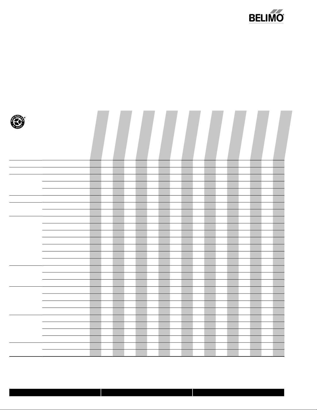
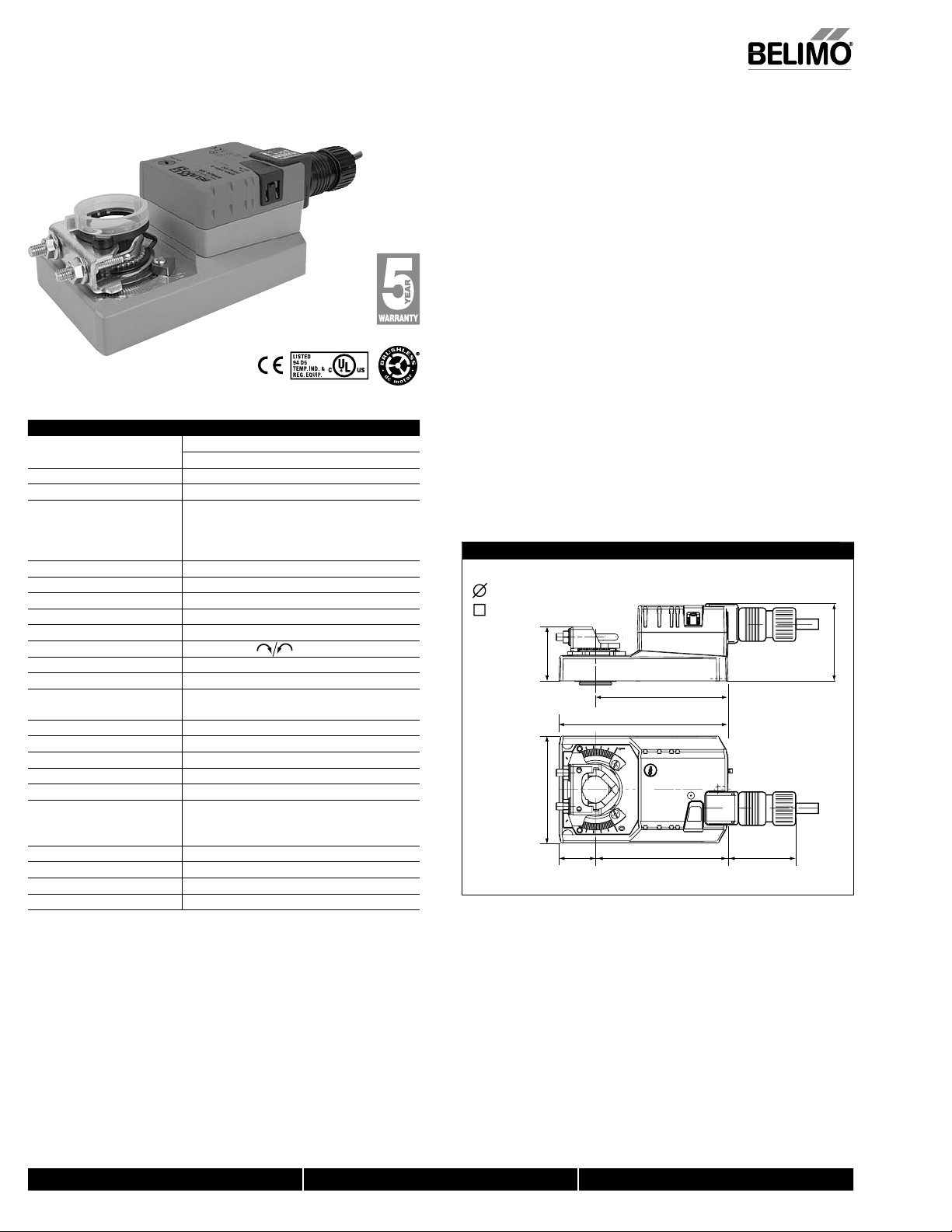
M Series Direct Coupled Actuato
r
Versatile and Powerful
*
AMB(X)24-3
AMX24-3-T
AMB24-3-T N4(H)
AMX120-3
AMB(X)24-SR
AMB24-SR-T N4(H)
AMX120-SR
AMB(X)24-MFT
AMCX24-MFT
(p. 229)
AMX24-MFT95
AMX24-PC
AMQB(X)24-1
AMQB(X)24-MFT
AMX24-LON
AMB24-3-S
AMX24-SR-T
AMX24-MFT-T N4(H)
●
Minimum 180 in-lb torque in a compact package.
For damper areas up to 45 sq. ft*, Q Series- 35 sq. ft
ll Actuator
have BD
AM Series - At A Glanc
Basic Product (B
Flexible Product
ue 180 in-lb [20 Nm
160 in-lb [16 Nm
140 in-lb [16 Nm
le of Rotation 95 degrees
Power Suppl
24 VAC/D
100 to 240 VA
ontrol Input
ff
On/Off, Floating Poin
2 to 10 VDC (4 to 20mA
unction Technolog
to 135 Oh
t
LonWORK
F
kN
2 to 10 VD
ariable (0 to 10 VDC
unning Time 95 seconds
. 7 to 20 secon
Adj. 95 to 300 seconds (150
150
Wiring Plenum Rated
Appliance Rated Cable
Terminal Stri
Conduit Fitting
uxiliary Switch Built-In
Add-On
Installation and Operation… (page 269).
●
40024 - 05/10 - Subject to change. © Belimo Aircontrols (USA), Inc.
●
*Based on 4 in-lb/f
2
damper torque loading. Parallel blade. No edge seals.
800-543-9038 USA 866-805-7089 CANADA 203-791-8396 LATIN AMERICA
21
Page 2
212
●
.
●
C
●
J
C
.
●
●
.
●
y
●
.
●
.
●
S
●
A
r
T
e
●
.
y.
●
.
bili
L
.
A
A CLOS
ER L
OOK…
j
g
(
)
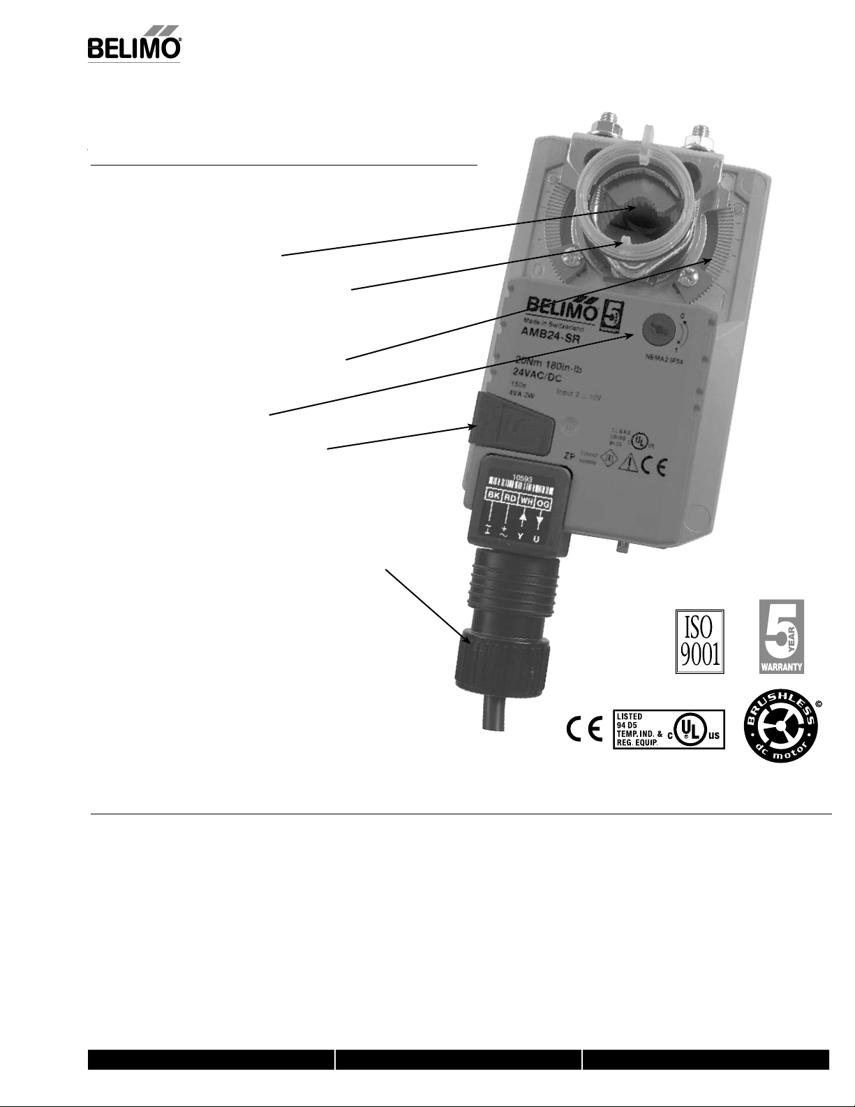
Brushless DC Motor for Added Accuracy and Controllability
ut Labor Costs with Simple Direct Coupling.
Self-Centers on 1/2",3/4", and 1.05"
ackshafts with Standard Clamp.
●
heck Damper Position with Clear Position Indicator
Don’t Worry about Actuator Burn-Out; Belimo is Overload Proof
throughout Rotation.
●
Enjoy Added Flexibility with Easy Mechanical Stops
to Adjust Angle of Rotation.
Need to Change Control Direction?
Do it easily with a Simple Switch
M Series Direct Coupled Actuato
Easily Accessible Manual Override Button helps
ou Pre-Tension Damper Blades.
Fully Adjustable Built-In Auxiliary Switch (AMB24-3-S)
Auxiliary Switch and Feedback Potentiometer Add-Ons Mount
Directly on Clamp, Includes Conduit Connector
tandard 3ft Plenum Rated Cable and Conduit Connector Provided
on Basic Models.
Added Flexibility to Select Clamp, Electrical Connection, and
Running Time to fit your Specific Application with Belimo’s New
Flexible Line of Actuators.
, Inc.
USA
e. © Belimo Aircontrols
ect to chan
he Belimo Differenc
ustomer Commitment
Extensive product range. Application assistance.
40024 - 05/10 - Sub
Same-day shipments. Free technical support. Five year warrant
Low Installation and Life-Cycle Cost
Easy installation. Accuracy and repeata
ow power consumption. No maintenance.
ty.
●
Long Service Life
Components tested before assembly. Every product tested before shipment.
30+ years direct coupled actuator design.
800-543-9038 USA 866-805-7089 CANADA 203-791-8396 LATIN AMERICA
Page 3

3
AMB(X)
24-3(-S)(-T
)
V
pply
z
n
)
T
g
)
n
e
S)
r
)
n
l
t
600
n
Torque
]
n
ibl
h
n
)
e
n
Auxiliary
h
)
C
e
d
y
)
e
]
S
g
l
Ag
†
/CS
acc
08/EEC and 2006/95/EC
el
)
g
ee
d
Weig
3
S
on
)
)
†
T
.
n
s
n
g
.
g
tuat
,
d
lding
.
s
g
.
A
.
2
On/Off, Floating Point, Non-Spring Return, 24
Technical Data AMB(X)24-3(-S)(-T)
ower su
ower consumptio
ransformer sizin
lectrical connectio
verload protectio
ontro
nput impedance
Angle of rotatio
Direction of rotatio
osition indicatio
anual overrid
switc
-S models
unning tim
umidit
Ambient temperatur
torage temperature -40°F to 176°F [-40°C to 80°C]
ousin
ousing materia
ency listings
ise lev
Servicin
uality standar
ht 2.2 lbs [1000 Kg] AMB24-
24 VAC ± 20% 50/60 H
24 VDC ± 10%
2.5 W (0.5 W
5.5 VA (Class 2 power source
3 ft, 18 GA plenum rated cabl
3 ft, 18 GA appliance rated cable (1/2” conduit connecto
protected NEMA 2 (IP54
electronic throughout 0 to 95° rotation
on/off, floating poin
Ω
max. 95°, adjust. with mechanical stop
180 in-lb [20 Nm
revers
e with switc
reflective visual indicator (snap-on
external push butto
1 x SPDT, 3A (0.5A) @ 250 VA
adj. 0 to 100%, UL approved
95 seconds, constant independent of loa
5 to 95% RH non condensing (EN 60730-1
-22°F to 122°F [-30°C to 50°C
NEMA 2, IP54, UL enclosure type 2
L94-5VA
cULus acc. to UL 60730-1A/-2-14,
AN
A E60730-1:02,
E
. to 2004/1
<45dB(A
maintenance fr
ISO 9001
2.4 lbs [1050 Kg] AMB24-3-
orque min. 180 in-lb for control of damper surfaces up to 45 sq ft
Applicatio
For on/off and floating point control of dampers in HVAC systems. Actuator sizing
hould be done in accordance with the damper manufacturer’s specifications.
The actuator is mounted directly to a damper shaft up to 1.05” in diameter by means
of its universal clamp, self-centered default. A crank arm and several mounting
rackets are available for applications where the actuator cannot be direct coupled to
the damper shaft.
Operatio
The actuator is not provided with and does not require any limit switches, but is
electronically protected a
actuator will prevent lateral movement
The AM... series provides 95° of rotation and a visual indicator indicates position of the
actuator. When reaching the damper or actuator end position, the actuator
automatically stops. The
or cover.
ac
The AM...24-3… actuators use a sensorless brushless DC motor
y an Application Specific Integrated Circuit (ASIC). The ASIC monitors and controls
the actuator’s rotation and provides a digital rotation sensing (DRS) function to prevent
amage to the actuator in a stall condition. Power consumption is reduced in ho
mode
The AM...24-3-S version is provided with 1 built-in auxiliary switch. This SPDT switch
s provided for safety interfacing or signaling, for example, for fan start-up. The
witching function is adjustable 0 to 95°. The auxiliary switch is double insulated so
an electrical
round connection is not necessary
dd-on auxiliary switches or feedback potentiometers are easily fastened directly onto
the actuator body for signaling and switching functions
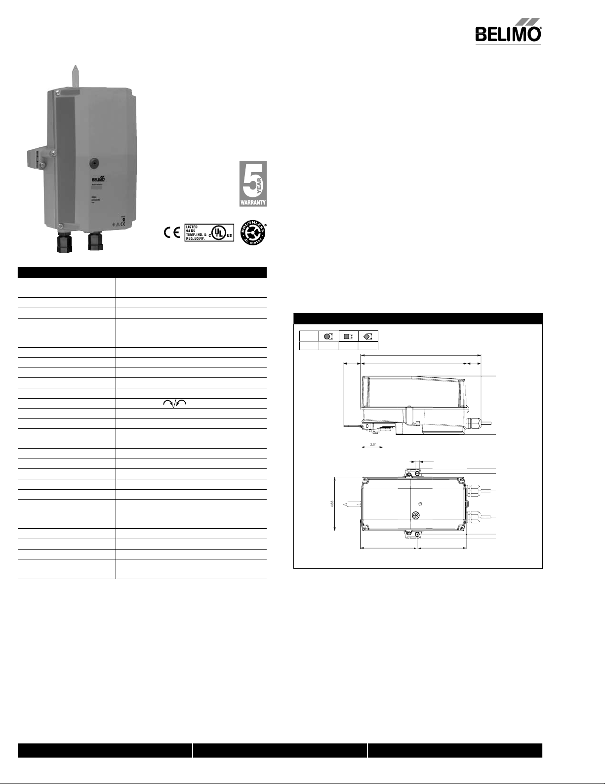
Dimensions (Inches [mm])
1/2” to 1.05” [12.7 to 26.67]
2/5” to 1.05” [10 to 26.67]
ainst overload. The anti-rotation strap supplied with the
ears can be manually disengaged with a button on the
2.2” [56]
3.46” [88]
1.18”
[30]
4.06” [103]
5.47” [139]
4.3” [109]
To center of
mounting slot.
2” [50.8]
which is controlled
2.49” [63.4]
12
AMB(X)24-3-T
lectrical connecti
screw terminal (for 26 to 14 GA wire
unprotected (NEMA 1/IP20
Rated Impulse Voltage 800V, Type of action 1, (1.B for -S version), Control Pollution Degree 3.
800-543-9038 USA 866-805-7089 CANADA 203-791-8396 LATIN AMERICA
21
40024 - 05/10 - Subject to change. © Belimo Aircontrols (USA), Inc.
Page 4

214
A
MB(X)24-3(-S)(-T
)
/Off
V
1
03
4
t
AV
s
2
g
g
T
6
A
)
h
A
NOTE:
.
w
a
a
c
c
w
S
.
.
,
:
.
e
.
Live Electrical Components!
-
.
ol
l
h
j
g
(
)
n
, Floating Point, Non-Spring Return, 24
Accessories
K-SA Reversible Clamp
ZG-100 Universal Mounting Bracket
ZG-10
ZG-1
ZG-10
Z-SMA AM/SM to AM Retrofit Mounting Bracke
ZG-NMA Crank arm Adaptor Kit
8-25 Universal Shaft Extension
ZG-JSA (-1, 2,3)Jackshaft Adaptors for Hollow Jackshaft
ZS-T Terminal Cover for NEMA
ZS-100 Weather Shield - Steel
ZS-150 Weather Shield - Polycarbonate
ZS-260 Explosion Proof Housin
ZS-300 (-1) (-5)NEMA 4X Housin
ool-0
PS-100 Actuator Power Supply Simulator
S1A, S2
P370 Shaft Mount Auxiliary Switc
…
When using AM...24-3… actuators, only use accessories listed on this page
Universal Mounting Bracket
Universal Mounting Bracket
Universal Mounting Bracket
8 mm & 10 mm Wrench
Auxiliary Switch (es
eedback Potentiometers
Typical Specification
Floating point, on/off control damper actuators shall be electronic direct-coupled type,
hich require no crank arm and linkage and be capable of direct mounting to a shaft
up to 1.05” diameter. Actuators shall have brushless DC motor technology and be
protected from overload at all angles of rotation. Actuators shall have reversing switch
nd manual override on the cover. If required, actuators shall be provided with one
djustable SPDT auxiliary switch. Actuators with auxiliary switches must be
onstructed to meet the requirements for double insulation so an electrical ground is
not required to meet agency listings. If required, actuators will be provided with a
screw terminal strip for electrical connections (AMX24-3-T). Run time shall be
onstant and independent of torque. Actuators shall be cULus listed, have a 5-year
arranty, and be manufactured under ISO 9001 International Quality Control
tandards. Actuators shall be as manufactured by Belimo
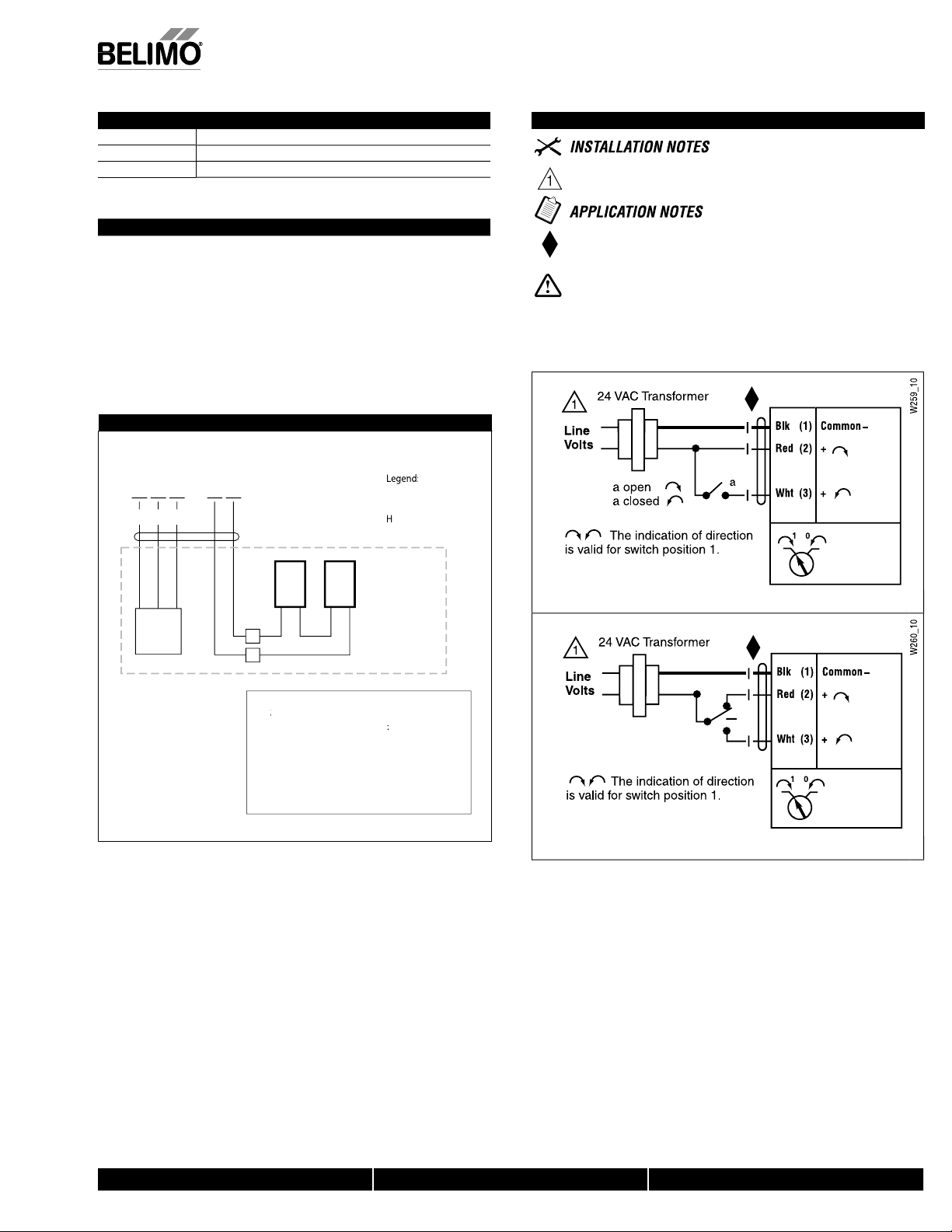
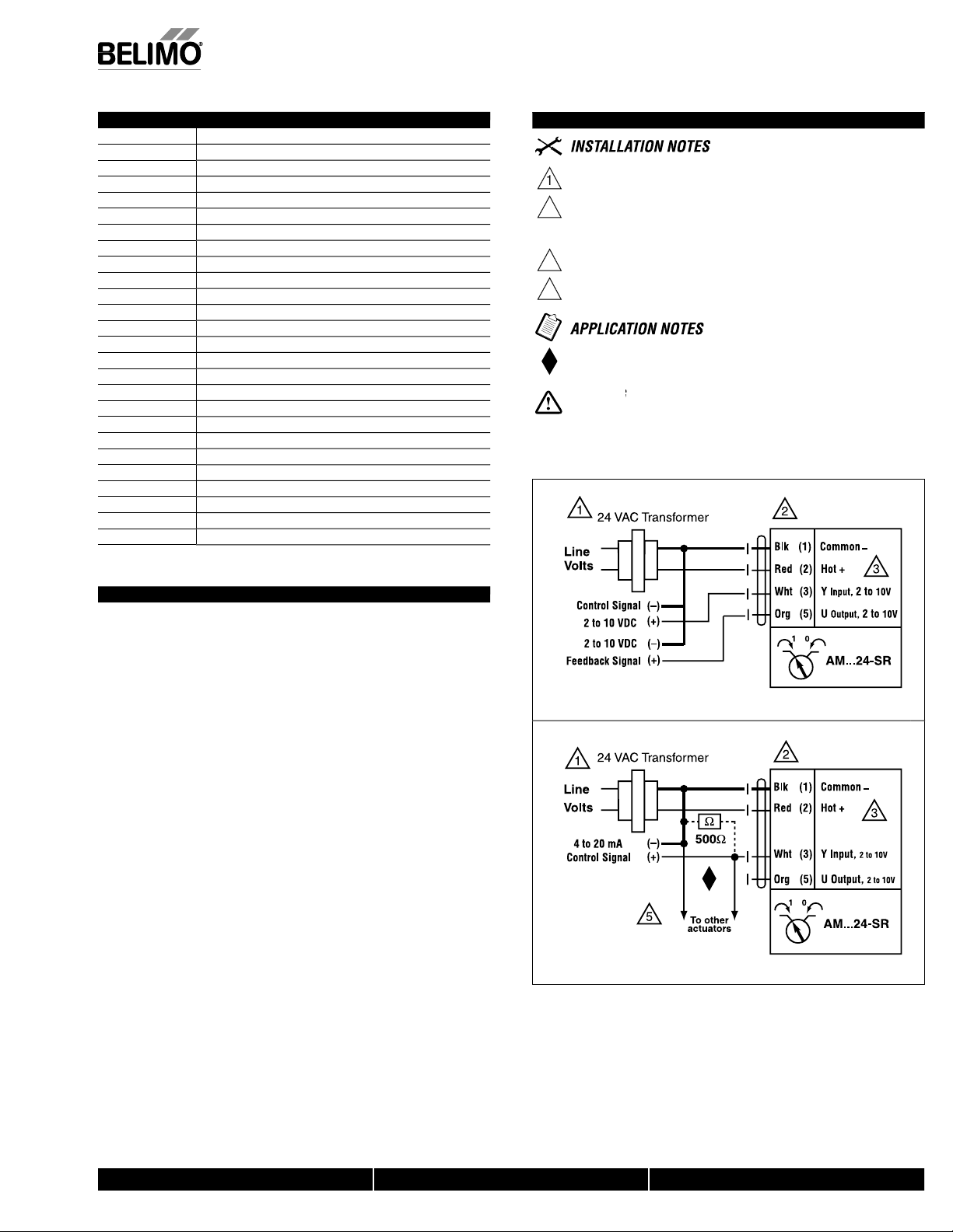
Wiring Diagrams
Provide overload protection and disconnect as required
Actuators may also be powered by 24 VDC.
For end position indication, interlock control, fan startup, etc.
AMB24-3-S incorporates one built-in auxiliary switches
1 x SPDT, 3A (0.5A) @250 VAC, UL Approved, adjustable 0 to 95
Meets cULus or UL and CSA Standard requirements without th
need of an electrical ground connection
During installation, testing, servicing and troubleshooting of this product, it may be
necessary to work with live electrical components. Have a qualifi ed licensed electrician or other
individual who has been properly trained in handling live electrical components perform these
tasks. Failure to follow all electrical safety precautions when exposed to live electrical compo
nents could result in death or serious injury
W259_08
On/Off contr
, Inc.
USA
e. © Belimo Aircontrols
ect to chan
W260_08
loating Point or On/Off contro
40024 - 05/10 - Sub
W258_08
Auxiliary Switc
800-543-9038 USA 866-805-7089 CANADA 203-791-8396 LATIN AMERICA
Page 5
5
AMB
24-3-T N4,
AMB
H
V
y
z
n
T
g
n
])
n
l
t
0
Ω
n
T
e
]
on
h
n
r
e
n
e
idi
(EN
)
e
g
]
g
7
l
g
†
,
l
)
g
ee
d
Weigh
]
Kg] with h
.
n
s
T
.
n
Th
p
.
T
tuat
T
c
c
.
.
9
0.52
0.2
5.154.
/
QE
...
/M/
...
/QE/
QE
...
/
M
24-3-T N4
EMA 4X, On/Off, Floating Point Control, Non-Spring Return, Direct Coupled, 24
Torque min. 160 in-lb for control of damper surfaces up to 40 sq ft
Applicatio
For on/off and floating point control of dampers in HVAC systems. Actuator sizing
hould be done in accordance with the damper manufacturer’s specifications.
he actuator is mounted directly to a damper shaft up to ¾” in diameter by means of
ts universal clamp, self-centered default
eratio
e actuator is not provided with and does not require any limit switches, but is
electronically protected against overload. The anti-rotation strap supplied with the
actuator will
he AMB24-3-T N4 provides 95° of rotation and a visual indicator indicates position of
the actuator. When reaching the damper or actuator end position, the actuator
automatically stops. The gears can be manually disengaged with a button on the
ac
he AMB24-3-T N4 actuator uses a sensorless brushless DC motor, which is
ontrolled by an Application Specific Integrated Circuit (ASIC). The ASIC monitors and
ontrols the actuator’s rotation and provides a digital rotation sensing (DRS) function to
Technical Data AMB24-3-T N4, AMB24-3-T N4H
ower suppl
ower consumptio
ransformer sizin
lectrical connectio
verload protectio
ontro
nput impedance 60
Angle of rotatio
orqu
Direction of rotati
osition indicatio
anual overrid
unning tim
um
ty 5 to 95% RH non condensing
Ambient temperatur
e temperature -40°F to 176°F [-40°C to 80°C
Stora
ousin
ousing materia
ency listings
A
oise leve
Servicin
uality standar
t 3.3 lbs [1.5 Kg
24 VAC ± 20% 50/60 H
24 VDC ± 10%
2.5 W (0.5 W) / heater 23 W
5.5 VA (Class 2 power source) / heater 20.5 VA
screw terminal (for 26 to 14 GA wire [heater 15
GA wire
1/2” conduit connector
electronic throughout 0 to 95° rotation
on/off, floating poin
max. 95°, adjust. with mechanical stop
160 in-lb [16 Nm
reversible wit
switch
pointe
external push butto
95 seconds
constant independent of load
60730-1
-22°F to 122°F [-30°C to 50°C]
UL Type 4X, NEMA 4X, IP66/6
L94-5VA
ccULus acc. to UL 60730-1A/-2-14,
CAN/CSA E60730-1, CSA C22.2 No. 24-93
CE acc. to 89/336/EEC
<45dB(A
maintenance fr
ISO 9001
3.7 lbs [1.6
eater
revent damage to the actuator in a stall condition. Power consumption is reduced in
olding mode
Add-on auxiliary switches or feedback potentiometers are easily fastened directly onto
the actuator body for signaling and switching functions
Dimensions (Inches)
AM..N4
revent lateral movement
or cover.
.56 1.1
1
41
21
40024 - 05/10 - Subject to change. © Belimo Aircontrols (USA), Inc.
800-543-9038 USA 866-805-7089 CANADA 203-791-8396 LATIN AMERICA
Page 6
216
A
EMA 4X, On
/Off
V
A
)
eedbac
s
.
w
a
c
c
.
g
.
e
.
!
fi
.
AMB24-3-T N4
On/Off
l
AMB24-3-T N4
l
3
actua
to
T
osta
t
g
oteThe f
ollo
k
en int
o account
ex
t
e
g
:
•
All
w
e
ar
be
av
oided.
•
her
e necessar
y
use cables
su
cient
actuat
o
.
j
g
(
)
MB24-3-T N4, AMB24-3-T N4H
, Floating Point Control, Non-Spring Return, Direct Coupled, 24
Accessories
PS-100 Actuator Power Supply Simulator
S1A, S2
P…A F
NOTE: When using AMB24-3… actuators, only use accessories listed on this page
Auxiliary Switch (es
k Potentiometer
Typical Specification
Floating point, on/off control damper actuators shall be electronic direct-coupled type,
hich require no crank arm and linkage and be capable of direct mounting to a shaft
up to ¾” diameter. Actuators shall have brushless DC motor technology and be
protected from overload at all angles of rotation. Actuators shall have reversing switch
nd manual override on the cover. If required, actuators needing auxiliary switches,
an be provided as an add-on accessory. Actuators with auxiliary switches must be
onstructed to meet the requirements for double insulation so an electrical ground is
not required to meet agency listings. Run time shall be constant and independent of
torque. Actuators shall be cULus listed, have a 5-year warranty, and be manufactured
under ISO 9001 International Quality Control Standards. Actuators shall be as
manufactured by Belimo
Wiring Diagrams
w
th actuator types ..-
N
1L2L3
NL
=
(°C) = Therm
= Heatin
Wiring Diagrams
rovide overload protection and disconnect as required
eets cULus or UL and CSA requirements without th
eed of an electrical ground connection
ARNINGLive Electrical Components
During installation, testing, servicing and troubleshooting of this product, it
may be necessary to work with live electrical components. Have a quali
electrician or other individual who has been properly trained in handling live electrical
components perform these tasks. Failure to follow all electrical safety precautions
when exposed to live electrical components could result in death or serious injury
ed licensed
HT
rnal wirin
en the cables or wires that
,
with
contro
, Inc.
USA
(°C)
M
1
2
N
wing points must be ta
with independent,
contact bet
e introduced and the heating element isto
W
mbers of wires, e.g. so that the heating and the
r can be supplied separately with votage
Heater wirin
e. © Belimo Aircontrols
ect to chan
40024 - 05/10 - Sub
loating Point or On/Off contro
800-543-9038 USA 866-805-7089 CANADA 203-791-8396 LATIN AMERICA
Page 7
7
AMX120-3
On/Off, Floating Point, Non-Spring Return, 100 to 240 VAC
pply
)
n
)
T
g
)
n
r
)
]
n
l
t
n
Torque
]
n
ibl
h
n
e
n
e
y
)
e
]
S
C]
g
l
A
†
C
l
)
S
g
ee
d
Weig
†
3
.
n
p
n
g
.
g
tuat
y
d
lding
.
.
2
Technical Data AMX120-3
ower su
ower consumptio
ransformer sizin
lectrical connectio
verload protectio
ontro
nput impedance 600
Angle of rotatio
Direction of rotatio
osition indicatio
anual overrid
unning tim
umidit
Ambient temperatur
torage temperature -40°F to 176°F [-40°C to 80°
ousin
ousing materia
gency listings
oise leve
ervicin
uality standar
ht 2.2 lbs [1.0 Kg]
Rated Impulse Voltage 4kV, Type of action 1, Control Pollution Degree
100 to 240 VAC, 50/60 Hz (nominal
85 to 265 VAC, 50/60 Hz (tolerance)
3 W (0.6 W
7 VA (Class 2 power source
18 GA appliance rated cable
1/2” conduit connecto
protected NEMA 2 (IP54
3 ft [1m] 10 ft [3m] 16 ft [5m
electronic throughout 0 to 95° rotation
on/off, floating poin
max. 95°, adjust. with mechanical stop
180 in-lb [20 Nm
revers
e with switc
reflective visual indicator (snap-on)
external push butto
300 seconds 150 seconds 95 seconds
constant independent of load
5 to 95% RH non condensing (EN 60730-1
-22°F to 122°F [-30°C to 50°C
NEMA 2/IP54
NEMA 2, IP54, UL enclosure type 2
cULus acc. to UL 60730-1A/-2-14,
CAN/CSA E60730-1:02,
E acc. to 2004/108/EEC and 2006/95/E
<45dB(A
maintenance fr
ISO 9001
Torque min. 180 in-lb for control of damper surfaces up to 45 sq ft
Applicatio
or on/off and floating point control of dampers in HVAC systems. Actuator sizing
should be done in accordance with the damper manufacturer’s specifications.
The actuator is mounted directly to a damper shaft up to 1.05” in diameter by means
of its universal clamp, self-centered default. A crank arm and several mounting
brackets are available for applications where the actuator cannot be direct coupled to
the dam
er shaft.
Operatio
The actuator is not provided with and does not require any limit switches, but is
electronically protected a
actuator will prevent lateral movement
The AMX series provides 95° of rotation and a visual indicator indicates position of the
actuator. When reaching the damper or actuator end position, the actuator
automatically stops. The
or cover.
ac
The AMX120-3 actuators use a sensorless brushless DC motor, which is controlled b
an Application Specific Integrated Circuit (ASIC). The ASIC monitors and controls the
actuator’s rotation and provides a digital rotation sensing (DRS) function to prevent
amage to the actuator in a stall condition. Power consumption is reduced in ho
mode
Add-on auxiliary switches or feedback potentiometers are easily fastened directly onto
the actuator body for signaling and switching functions
Dimensions (Inches [mm])
1/2” to 1.05” [12.7 to 26.67]
2/5” to 1.05” [10 to 26.67]
ainst overload. The anti-rotation strap supplied with the
ears can be manually disengaged with a button on the
2.2” [56]
3.46” [88]
1.18”
[30]
4.06” [103]
5.47” [139]
4.3” [109]
To center of
mounting slot.
2” [50.8]
2.49” [63.4]
D12
21
800-543-9038 USA 866-805-7089 CANADA 203-791-8396 LATIN AMERICA
40024 - 05/10 - Subject to change. © Belimo Aircontrols (USA), Inc.
Page 8

218
A
n
/Off
C
1
03
4
t
AV
s
g
Tool-06
8
S
A
)
h
NOTE:
AMX
w
a
f
.
.
!
e
.
Live Electrical Components!
.
On/Off
j
g
(
)
, Floating Point, Non-Spring Return, 100 to 240 VA
MX120-3
Accessories
K-SA Reversible Clamp
ZG-100 Universal Mounting Bracket
ZG-10
ZG-1
ZG-10
Z-SMA AM/SM to AM Retrofit Mounting Bracke
ZG-NMA Crank arm Adaptor Kit
8-25 Universal Shaft Extension
ZG-JSA (-1, 2,3)Jackshaft Adaptors for Hollow Jackshaft
ZS-100 Weather Shield - Steel
ZS-150 Weather Shield - Polycarbonate
ZS-260 Explosion Proof Housing
ZS-300 (-1) (-5)NEMA 4X Housin
PS-100 Actuator Power Supply Simulator
1A, S2
P370 Shaft Mount Auxiliary Switc
P…A Feedback Potentiometers
When using
Universal Mounting Bracket
Universal Mounting Bracket
Universal Mounting Bracket
mm & 10 mm Wrench
Auxiliary Switch (es
120-3 actuators, only use accessories listed on this page.
Typical Specification
Floating point, on/off control damper actuators shall be electronic direct-coupled type,
hich require no crank arm and linkage and be capable of direct mounting to a shaft
up to 1.05” diameter. Actuators shall have brushless DC motor technology and be
protected from overload at all angles of rotation. Actuators shall have reversing switch
nd manual override on the cover. Run time shall be constant and independent o
torque. Actuators shall be cULus listed, have a 5-year warranty, and be manufactured
under ISO 9001 International Quality Control Standards. Actuators shall be as
manufactured by Belimo
Wiring Diagrams
rovide overload protection and disconnect as required
AUTION
2
Actuators may be connected in parallel.
ower consumption and input impedance must be observed.
Meets cULus or UL and CSA Standard requirements without th
eed of an electrical ground connection
During installation, testing, servicing and troubleshooting of this product, it may be
ecessary to work with live electrical components. Have a qualifi ed licensed electrician or other
ndividual who has been properly trained in handling live electrical components perform these
tasks. Failure to follow all electrical safety precautions when exposed to live electrical compo-
ents could result in death or serious injury
quipment Damage
control
, Inc.
USA
e. © Belimo Aircontrols
ect to chan
Floating Point or On/Off control
40024 - 05/10 - Sub
800-543-9038 USA 866-805-7089 CANADA 203-791-8396 LATIN AMERICA
Page 9

9
AMB(X)
24-SR(-T)
.
n
p
.
li
.
n
g
ill p
.
h
(X)
d
g
.
.
2
y
z
n
W)
T
g
)
n
e
r
)
]
n
A
Ω
)
n
Torque
]
n
s
ch
:
)
)
n
)
ide
n
e
p
)
Ambi
e
S
C]
g
l
g
†
/CS
acc
08/EEC and 2006/95/EC
l
dB(A)
S
g
ee
d
Weig
g]
n
)
†
.
Proportional, Non-Spring Return, 24 V, for 2 to 10 VDC or 4 to 20 mA
Technical Data AMB(X)24-SR(-T)
ower suppl
ower consumptio
ransformer sizin
lectrical connectio
verload protectio
perating range Y 2 to 10 VDC, 4 to 20 m
nput impedance 100 kΩ (0.1 mA), 500
eedback output U 2 to 10 VDC (max 0.5 mA
Angle of rotatio
Direction of rotatio
osition indicatio
anual overr
unning tim
umidity 5 to 95% RH non condensing (EN 60730-1
ent temperatur
torage temperature -40°F to 176°F [-40°C to 80°
ousin
ousing materia
ency listings
A
oise leve
ervicin
uality standar
ht 2.2 lbs [1000 K
AMB(X)24-SR-T
ectrical connectio
Rated Impulse Voltage 800V, Type of action 1, Control Pollution Degree 3
24 VAC ± 20% 50/60 H
24 VDC ± 10%
2.5 W (0.4
5 VA (Class 2 power source
18 GA plenum rated cabl
1/2” conduit connecto
protected NEMA 2 (IP54
3 ft [1m] 10 ft [3m] 16 ft [5m
electronic throughout 0 to 95° rotation
max. 95°, adjust. with mechanical stop
180 in-lb [20 Nm
reversible with
wit
actuator will move
=CCW with decreasing control signal (10 to 2V
=CW with decreasing control signal (10 to 2V
reflective visual indicator (snap-on
external push butto
300 seconds 150 seconds 95 seconds
constant inde
endent of load
-22°F to 122°F [-30°C to 50°C]
NEMA 2, IP54, UL enclosure type 2
UL94-5VA
cULus acc. to UL 60730-1A/-2-14,
AN
A E60730-1:02,
E
. to 2004/1
<45
maintenance fr
ISO 9001
screw terminal (for 26 to 14 GA wire)
unprotected (NEMA 1/IP20
Torque min. 180 in-lb for control of damper surfaces up to 45 sq ft
Applicatio
or proportional modulation of dampers in HVAC systems. Actuator sizing should be
done in accordance with the damper manufacturer’s specifications.
The actuator is mounted directly to a damper shaft up to 1.05” in diameter by means
of its universal clamp, 1/2” self-centered default. A crank arm and several mounting
brackets are available for applications where the actuator cannot be direct coupled to
the dam
er shaft
The actuator operates in response to a 2 to 10 VDC, or with the addition of a
500
resistor, a 4 to 20 mA control input from an electronic controller or positioner.
A 2 to 10 VDC feedback signal is provided for position indication or master-slave
app
cations
Operatio
The actuator is not provided with and does not require any limit switches, but is
electronically protected a
actuator w
revent lateral movement
The AMB(X) series provides 95° of rotation and a visual indicator indicates position of
e actuator. When reaching the damper or actuator end position, the actuator
t
automatically stops. The gears can be manually disengaged with a button on the
actuator cover.
The AMB
24-SR… actuators use a sensorless brushless DC motor, which is
controlled by an Application Specific Integrated Circuit (ASIC). The ASIC monitors and
controls the actuator’s rotation and provides a digital rotation sensing (DRS) function to
prevent
amage to the actuator in a stall condition. Power consumption is reduced in
mode
holdin
Add-on auxiliary switches or feedback potentiometers are easily fastened directly onto
the actuator body for signaling and switching functions
Dimensions (Inches [mm])
1/2” to 1.05” [12.7 to 26.67]
2/5” to 1.05” [10 to 26.67]
ainst overload. The anti-rotation strap supplied with the
2.2” [56]
4.06” [103]
5.47” [139]
3.46” [88]
1.18”
[30]
4.3” [109]
To center of
mounting slot.
2” [50.8]
2.49” [63.4]
12
40024 - 05/10 - Subject to change. © Belimo Aircontrols (USA), Inc.
21
800-543-9038 USA 866-805-7089 CANADA 203-791-8396 LATIN AMERICA
Page 10
220
A
MB(X)24-SR(-T)
SA
0
t
t
03
t
t
A
A
t
A
AV
5
n
s
T
2
0
l
0
e
0
g
g
6
S
A
A
)
0
S
A
s
NEMA
g
SG
g
0
0
e
A
n
S
le
0
r
.
h
t
g
s
s
f
.
.
!
.
o
.
Live Electrical Components!
f
.
_
8
_
4 to
ol
j
g
(
)
Proportional, Non-Spring Return, 24 V, for 2 to 10 VDC or 4 to 20 mA
Accessories
ZG-10
ZG-101 Universal Mounting Bracke
ZG-1
ZG-104 Universal Mounting Bracke
Z-SM
ZG-NM
8-2
ZG-JSA (-1, 2, 3)Jackshaft Adaptors for Hollow Jackshaft
ZSZS-10
ZS-15
ZS-26
ZS-300 (-1) (-5)NEMA 4X Housin
Tool-0
1A, S2
37
…
SGA24
F24 Min positioners for flush panel mountin
TA-25
RM-10
ADS-100
ZG-R01 Resistor for 4 to 20 mA Conversio
V24 U
ZG-X4
NOTE: When using AMB(X)24-SR… actuators, only use accessories listed on this page
Reversible Clamp
niversal Mounting Bracke
Universal Mounting Bracke
M/SM to AM Retrofit Mounting Bracke
rank arm Adaptor Kit
Universal Shaft Extensio
Terminal Cover NEMA
Weather Shield - Stee
Weather Shield - Polycarbonat
Explosion Proof Housin
8 mm & 10 mm Wrench
uxiliary Switch (es
haft Mount Auxiliary Switch
Feedback Potentiometer
n positioners in
4 housin
Pulse Width Modulation Interface
Input Rescaling Modul
nalog to Digital Switch
attery Back-Up Modu
Transforme
Wiring Diagrams
rovide overload protection and disconnect as required
AUTION
2
Actuators may be connected in parallel.
ower consumption and input impedance must be observed.
Actuators may also be powered by 24 VDC.
nly connect common to neg. (–) leg of control circuits
The ZG-R01 500
2 to 10 VDC, up to 2 actuators may be connected in parallel
During installation, testing, servicing and troubleshooting of this product, it may be
ecessary to work with live electrical components. Have a qualifi ed licensed electrician or other
ndividual who has been properly trained in handling live electrical components perform these
tasks. Failure to
ents could result in death or serious injury
quipment Damage
resistor converts the 4 to 20 mA control signal t
ollow all electrical safety precautions when exposed to live electrical compo-
0
W257
Typical Specification
roportional control damper actuators shall be electronic direct-coupled type, whic
require no crank arm and linkage and be capable of direct mounting to a shaft up to
1.05” diameter. Actuators must provide proportional damper control in response to a 2
o 10 VDC or, with the addition of a 500 Ωresistor, a 4 to 20 mA control input from an
electronic controller or positioner. Actuators shall have brushless DC motor technology
and be protected from overload at all angles of rotation. Actuators shall have reversin
witch and manual override on the cover. If required, actuator will be provided with
, Inc.
crew terminal strip for electrical connections (AMX24-SR-T). Run time shall be
USA
constant and independent of torque. A 2 to 10 VDC feedback signal shall be provided
or position indication. Actuators shall be cULus listed, have a 5-year warranty, and be
anufactured under ISO 9001 International Quality Control Standards. Actuators shall
be as manufactured by Belimo
e. © Belimo Aircontrols
ect to chan
40024 - 05/10 - Sub
2 to 10 VDC control
08
W257
20 mA contr
800-543-9038 USA 866-805-7089 CANADA 203-791-8396 LATIN AMERICA
Page 11

1
A
MB24-SR-T N4, AMB24-SR-T N4H
z
n
T
g
A
on
])
r
n
A
0
Ω
)
n
T
e
n
h
s
n
r
de
n
e
d
y
)
Ambi
e
g
7
l
g
†
,
,
C
el
)
S
g
ee
d
Weig
g]
†
.
T
.
n
T
T
0
a
.
n
Th
el
a
.
T
o
a
actuat
T
c
c
.
A
t
.561.10
8
AM..N4
QE
...
/M/
...
/QE/
QE
...
NEMA 4X, Proportional Control, Non-Spring Return, Direct Coupled, 24V, for 2 to 10 VDC and 4 to 20 mA
orque min. 160 in-lb for control of damper surfaces up to 40 sq ft
Applicatio
or proportional modulation of dampers in HVAC systems. Actuator sizing should be
done in accordance with the damper manufacturer’s specifications.
he actuator is mounted directly to a damper shaft up to ¾” in diameter by means of
ts universal clamp.
he actuator operates in response to a 2 to 10 VDC, or with the addition of a 50
esistor, a 4 to 20 mA control input from an electronic controller or positioner. A 2 to
0 VDC feedback signal is provided for position indication or master-slave
pplications
peratio
e actuator is not provided with and does not require any limit switches, but is
ectronically protected against overload. The anti-rotation strap supplied with the
ctuator will prevent lateral movement
he AMB24-SR-T N4 provides 95° of rotation and a visual indicator indicates position
f the actuator. When reaching the damper or actuator end position, the actuator
utomatically stops. The gears can be manually disengaged with a button on the
Technical Data AMB24-SR-T N4, AMB24-SR-T N4H
ower supply 24 VAC ± 20% 50/60 H
ower consumptio
ransformer sizin
lectrical connecti
verload protectio
perating range Y 2 to 10 VDC, 4 to 20 m
nput impedance 100 kΩ (0.1 mA), 50
eedback output U 2 to 10 VDC (max 0.5 mA
Angle of rotatio
orqu
Direction of rotatio
osition indicatio
nual overri
unning tim
umidit
ent temperatur
Storage temperature -40°F to 176°F [-40°C to 80°C]
ousin
ousing materia
ency listings
A
ise lev
ervicin
uality standar
ht 3.3 lbs [1.5 K
Rated Impulse Voltage 800V, Type of action 1, Control Pollution Degree 3
24 VDC ± 10%
2.5 W (0.4 W) / heater 23 W
5 VA (Class 2 power source) / heater 20 V
screw terminal (for 26 to 14 GA wire [heater 15
GA wire
1/2” conduit connecto
electronic throughout 0 to 95° rotation
max. 95°, adjust. with mechanical stop
160 in-lb [16 Nm]
reversible wit
witch
pointe
external push butto
95 seconds, constant independent of loa
5 to 95% RH non condensing (EN 60730-1
-22°F to 122°F [-30°C to 50°C]
UL type 4X, NEMA 4X, IP66/6
L94-5VA
cULus acc. to UL 60730-1A/-2-14
CAN/CSA E60730-1, CSA C22.2 No. 24-93
E acc. to 89/336/EE
<45dB(A
maintenance fr
ISO 9001
3.7 lbs [1.6 Kg] with heater
or cover.
he AMBX24-SR-T N4 actuator uses a sensorless brushless DC motor, which is
ontrolled by an Application Specific Integrated Circuit (ASIC). The ASIC monitors and
ontrols the actuator’s rotation and provides a digital rotation sensing (DRS) function to
revent damage to the actuator in a stall condition. Power consumption is reduced in
olding mode
dd-on auxiliary switches or feedback potentiometers are easily fastened directly onto
he actuator body for signaling and switching functions.
Dimensions (Inches [mm])
/
4.
9
40024 - 05/10 - Subject to change. © Belimo Aircontrols (USA), Inc.
800-543-9038 USA 866-805-7089 CANADA 203-791-8396 LATIN AMERICA
22
Page 12

222
A
MX24-SR-T N4, AMX24-SR-T N4H
S
A
A
s
SG
g
SG
g
50
odulatio
face
0
le
00
A
on
S
e
0
r
h
g
s
A
A
.
g
!
3
.
0
Ω
o
.
!
-
t
comp
w
.
AMB24-SR-T N4
AMB24-SR-T N4
4
l
actua
to
T (°C)
osta
t
g
te
The f
ollo
k
en int
o account
ex
t
e
g
:
tact betw
een the cables o
r
es that
ar
e
to
be avoided.•Where necessar
y
use cables
su
cientnumbers o
actuat
o
t
el
.
F
T
j
g
(
)
EMA 4X, Proportional Control, Non-Spring Return, Direct Coupled, 24V, for 2 to 10 VDC and 4 to 20 mA
Accessories
1A, S2
…
A24 Min positioners for surface mountin
F24 Min positioners for flush panel mountin
TA-2
-10
ADS-1
ZG-R01 Resistor for 4 to 20 mA Conversi
SV24 U
ZG-X4
uxiliary Switch (es)
Feedback Potentiometer
Pulse Width M
nput Rescaling Modu
nalog to Digital Switch
Battery Back-Up Modul
Transforme
n Inter
Typical Specification
roportional control damper actuators shall be electronic direct-coupled type, whic
require no crank arm and linkage and be capable of direct mounting to a shaft up to
¾” diameter. Actuators must provide proportional damper control in response to a 2 to
10 VDC or, with the addition of a 500 Ω resistor, a 4 to 20 mA control input from an
electronic controller or positioner. Actuators shall have brushless DC motor technology
and be protected from overload at all angles of rotation. Actuators shall have reversin
witch and manual override on the cover. Run time shall be constant and independent
of torque. A 2 to 10 VDC feedback signal shall be provided for position indication.
ctuators shall be cULus listed, have a 5-year warranty, and be manufactured under
SO 9001 International Quality Control Standards. Actuators shall be as manufactured
by Belimo
Wiring Diagram
ith actuator types ..-SR or M
T
N
1L23512
NL
egend:
=
= Therm
= Heatin
Wiring Diagram
rovide overload protection and disconnect as required.
AUTION
2
Actuators may be connected in parallel.
quipment damage
ower consumption and input impedance must be observed.
Actuators may also be powered by 24 VDC.
nly connect common to neg. (–) leg of control circuits
The ZG-R01 50
esistor converts the 4 to 20 mA control signal t
2 to 10 VDC, up to 2 actuators may be connected in parallel
ARNINGive Electrical Components
uring installation, testing, servicing and troubleshooting of this product, it may be
ecessary to work with live electrical components. Have a qualified licensed elec
rician or other individual who has been properly trained in handling live electrical
onents perform these tasks. Failure to follow all electrical safety precautions
hen exposed to live electrical components could result in death or serious injury
T
,
H
2 to 10 VDC control
rnal wirin
r wi
with
y with votage
, Inc.
USA
e. © Belimo Aircontrols
ect to chan
(°C)
M
1
2
wing points must be ta
with independent,
• All con
introduced and the heating element is
f wires, e.g. so that the heating and the
r can be supplied separa
Heater wirin
40024 - 05/10 - Sub
to 20 mA contro
800-543-9038 USA 866-805-7089 CANADA 203-791-8396 LATIN AMERICA
Page 13

3
A
MX120-
SR
A
)
n
)
T
g
)
n
r
)
]
n
A
Ω
)
n
T
e
]
n
ibl
h
h
:
)
)
on
de
n
e
)
e
]
S
g
l
Ag
†
,
C
el
)
S
g
ee
d
900
W
†
.
.
n
p
.
li
.
n
g
ill p
.
Wh
S
d
lding
.
.
2
Proportional, Non-Spring Return, 100 to 240 VAC, for 2 to 10 VDC or 4 to 20 m
Torque min. 180 in-lb for control of damper surfaces up to 45 sq ft
Applicatio
or proportional modulation of dampers in HVAC systems. Actuator sizing should be
done in accordance with the damper manufacturer’s specifications.
The actuator is mounted directly to a damper shaft up to 1.05” in diameter by means
of its universal clamp, 1/2” self-centered default. A crank arm and several mounting
brackets are available for applications where the actuator cannot be direct coupled to
the dam
The actuator operates in response to a 2 to 10 VDC, or with the addition of a
500
A 2 to 10 VDC feedback signal is provided for position indication or master-slave
app
cations
Operatio
The actuator is not provided with and does not require any limit switches, but is
electronically protected a
actuator w
The AMX series provides 95° of rotation and a visual indicator indicates position of the
actuator.
automatically stops. The gears can be manually disengaged with a button on the
actuator cover.
The AMX120-SR actuators use a sensorless brushless DC motor, which is controlled
by an Application
Technical Data AMX120-SR
ower supply 100 to 240 VAC, 50/60 Hz (nominal
85 to 265 VAC, 50/60 Hz (tolerance)
ower consumptio
ransformer sizin
lectrical connectio
verload protectio
perating range Y 2 to 10 VDC, 4 to 20 m
nput impedance 100 kΩ (0.1 mA), 500
eedback output U 2 to 10 VDC (max 0.5 mA
Angle of rotatio
orqu
Direction of rotatio
ition indicati
nual overri
unning tim
umidity 5 to 95% RH non condensing (EN 60730-1
Ambient temperatur
torage temperature -40°F to 176°F [-40°C to 80°C]
ousin
ousing materia
ency listings
ise lev
ervicin
uality standar
eight 2.2 lbs [1.0 Kg]
Rated Impulse Voltage 4kV, Type of action 1, Control Pollution Degree 3
4 W (1 W
7.5 VA (Class 2 power source
18 GA appliance rated cable
1/2” conduit connecto
protected NEMA 2 (IP54
3 ft [1m] 10 ft [3m] 16 ft [5m
electronic throughout 0 to 95° rotation
max. 95°, adjust. with mechanical stop
180 in-lb [20 Nm
revers
e wit
actuator will move
=CCW with decreasing control signal (10 to 2V
=CW with decreasing control signal (10 to 2V
reflective visual indicator (snap-on)
external push butto
300 seconds 150 seconds 95 seconds
constant independent of load
-22°F to 122°F [-30°C to 50°C
2, IP54, UL enclosure type 2
L94-5VA
cULus acc. to UL 60730-1A/-2-14,
CAN/CSA E60730-1:02
E acc. to 2004/108/EEC and 2006/95/E
<45dB(A
maintenance fr
ISO
1
switc
actuator’s rotation and provides a digital rotation sensing (DRS) function to prevent
amage to the actuator in a stall condition. Power consumption is reduced in ho
mode
Add-on auxiliary switches or feedback potentiometers are easily fastened directly onto
the actuator body for signaling and switching functions
Dimensions (Inches [mm])
er shaft
resistor, a 4 to 20 mA control input from an electronic controller or positioner.
ainst overload. The anti-rotation strap supplied with the
revent lateral movement
en reaching the damper or actuator end position, the actuator
pecific Integrated Circuit (ASIC). The ASIC monitors and controls the
143_
40024 - 05/10 - Subject to change. © Belimo Aircontrols (USA), Inc.
800-543-9038 USA 866-805-7089 CANADA 203-791-8396 LATIN AMERICA
22
Page 14

224
A
MX120-
SR
A
1
03
4
t
AV
s
g
Tool-06
8
A
)
S
h
g
4
g
50
odulatio
ace
0
A
1
r
NOTE:
a
g
o
A
A
.
.
!
.
e
.
o
.
Live Electrical Components!
.
_
l
j
g
(
)
roportional, Non-Spring Return, 100 to 240 VAC, for 2 to 10 VDC or 4 to 20 m
Accessories
K-SA Reversible Clamp
ZG-100
ZG-10
ZG-1
ZG-10
Z-SMA AM/SM to AM Retrofit Mounting Bracke
ZG-NMA Crank arm Adaptor Kit
8-25 Universal Shaft Extension
ZG-JSA (-1, 2, 3)Jackshaft Adaptors for Hollow Jackshaft
ZS-100 Weather Shield - Steel
ZS-150 Weather Shield - Polycarbonate
ZS-260 Explosion Proof Housing
ZS-300 (-1) (-5)NEMA 4X Housin
S1A, S2
370
P…A Feedback Potentiometers
SGA24 Min positioners in NEMA 4 housin
SGF2
PTA-2
IRM-10
DS-100 Analog to Digital Switch
ZG-R0
NSV24 US
ZG-X40 Transforme
When using AMX120-SR actuators, only use accessories listed on this page.
niversal Mounting Bracket
Universal Mounting Bracket
Universal Mounting Bracket
Universal Mounting Bracket
mm & 10 mm Wrench
Auxiliary Switch (es
haft Mount Auxiliary Switc
Min positioners for flush panel mountin
Pulse Width M
Input Rescaling Module
Resistor for 4 to 20 mA Conversion
attery Back-Up Module
n Interf
Wiring Diagram
rovide overload protection and disconnect as required
AUTION
2
Actuators may be connected in parallel.
ower consumption and input impedance must be observed.
Only connect common to neg. (–) leg of control circuits
Meets cULus or UL and CSA Standard requirements without th
eed of an electrical ground connection
The ZG-R01 500
2 to 10 VDC, up to 2 actuators may be connected in parallel
During installation, testing, servicing and troubleshooting of this product, it may be
ecessary to work with live electrical components. Have a qualifi ed licensed electrician or other
ndividual who has been properly trained in handling live electrical components perform these
tasks. Failure to follow all electrical safety precautions when exposed to live electrical compo-
ents could result in death or serious injury
quipment Damage
resistor converts the 4 to 20 mA control signal t
08
W374
Typical Specification
roportional control damper actuators shall be electronic direct-coupled type, which
require no crank arm and linkage and be capable of direct mounting to a shaft up to
.05” diameter. Actuators must provide proportional damper control in response to a 2
to 10 VDC or, with the addition of a 500Ω resistor, a 4 to 20 mA control input from an
electronic controller or positioner. Actuators shall have brushless DC motor technology
nd be protected from overload at all angles of rotation. Actuators shall have reversin
switch and manual override on the cover. Run time shall be constant and independent
f torque. A 2 to 10 VDC feedback signal shall be provided for position indication.
, Inc.
ctuators shall be cULus listed, have a 5-year warranty, and be manufactured under
ISO 9001 International Quality Control Standards. Actuators shall be as manufactured
USA
by Belimo
2 to 10 VDC or 4 to 20 mA contro
e. © Belimo Aircontrols
ect to chan
40024 - 05/10 - Sub
800-543-9038 USA 866-805-7089 CANADA 203-791-8396 LATIN AMERICA
Page 15

5
50/60 Hz
n
T
g
)
n
e
r
)
]
n
)
)
Ω
)
x
f
n
y
e
Torque
]
on
s
ch
n
)
de
n
e
(
)
idity
(EN
)
Ambi
e
C]
]
g
l
g
†
C
el
)
g
ee
d
900
Weigh
kg]
†
.
AMB(X)
24-
MFT
®
.
n
p
.
C
so
e.
n
l
p
.
f
(X)
g
g
g
.
.
1.18" [30]
]
03]
]
]
6
88]
9
63
2
8]
3
Proportional, Non-Spring Return, 24 V, Multi-Function Technology
Technical Data AMB(X)24-MFT
ower supply 24 VAC ± 20%
ower consumptio
ransformer sizin
lectrical connectio
verload protectio
perating range Y 2 to 10 VDC, 4 to 20 mA (default
nput impedance 100 kΩ (0.1 mA), 500
eedback output U 2 to 10 VDC, 0.5 mA ma
rotatio
Angle o
Direction of rotati
osition indicatio
nual overri
unning tim
um
ent temperatur
Storage temperature -40°F to 176°F [-40°C to 80°C
ousin
ousing materia
ency listings
A
ise lev
Servicin
uality standar
t 2.6 lbs [1.2
Rated Impulse Voltage 800V, Type of action 1, Control Pollution Degree 3
24 VDC ± 10%
3.5 W (1.3 W)
6 VA (Class 2 power source
18 GA plenum rated cabl
1/2” conduit connecto
protected NEMA 2 (IP54
3 ft [1m] 10 ft [3m] 16 ft [5m
electronic throughout 0 to 95° rotation
variable (VDC, PWM, floating point, on/off
1500 W (PWM, floating point, on/off
VDC variable
max. 95°, adjustable with mechanical stop
electronicall
variabl
180 in-lb [20 Nm
reversible with
wit
reflective visual indicator (snap-on
external push butto
150 seconds (default)
variable
90 to 350 seconds
5 to 95% RH non condensing
60730-1
-22°F to 122°F [-30°C to 50°
NEMA 2, IP54, UL enclosure type 2
L94-5VA
cULus acc. to UL 60730-1A/-2-14,
CAN/CSA E60730-1:02,
E acc. to 2004/108/EEC and 2006/95/E
<45dB(A
maintenance fr
ISO
1
Torque min. 180 in-lb for control of damper surfaces up to 45 sq ft
Applicatio
or proportional modulation of dampers in HVAC systems. Actuator sizing should be
done in accordance with the damper manufacturer’s specifications.
The actuator is mounted directly to a damper shaft up to 1.05” in diameter by means
of its universal clamp, 1/2” self-centered default. A crank arm and several mounting
brackets are available for applications where the actuator cannot be direct coupled to
the dam
er shaft
The default parameters for 2 to 10 VDC applications of the …MFT actuator are
assigned during manufacturing. If necessary, custom versions of the actuators can be
ordered. The parameters can be changed by two means: pre-set and custom
configurations from Belimo or on-site configurations using the Belimo P
-Tool
ftwar
Operatio
The actuator is not provided with and does not require any limit switches, but is
ectronically protected against overload. The anti-rotation strap supplied with the
e
actuator will
The AMB(X) series provides 95° of rotation and a visual indicator indicates position o
the actuator. When reaching the damper or actuator end position, the actuator
automatically stops. The gears can be manually disengaged with a button on the
actuator cover.
The AMB
Application Specific Integrated Circuit (ASIC). The ASIC monitors and controls the
actuator’s rotation and provides a di
dama
mode
Add-on auxiliary switches or feedback potentiometers are easily fastened directly onto
the actuator body for signaling and switching functions
Dimensions (Inches [mm])
revent lateral movement
24-MFT actuators use a brushless DC motor, which is controlled by an
ital rotation sensing (DRS) function to prevent
e to the actuator in a stall condition. Power consumption is reduced in holdin
1/2” to 1.05” [12.7 to 26.67]
2/5” to 1.05” [10 to 26.67]
.4]
" [
.4
4.06" [1
4.3" [109
5.2" [131
" [
.4
8.3" [211
" [50.
D14
40024 - 05/10 - Subject to change. © Belimo Aircontrols (USA), Inc.
22
800-543-9038 USA 866-805-7089 CANADA 203-791-8396 LATIN AMERICA
Page 16

226
SA
0
t
t
03
t
t
A
A
t
A
AV
5
n
s
0
l
0
e
0
g
06
8
A
A
0
S
s
g
00
A
n
S
e
0
r
AMB(X)
MFT
.
t
s
.
d.
!
A
shaf
eedback cannot be used
.
T
)
.
8
osures
acs.
.
9
.
The ZG-R01 500
.
Live Electrical Components!
fi
g
-
.
8
V
A
On/Off control
8
l
A
MB(X)24-MFT
®
j
g
(
)
roportional, Non-Spring Return, 24 V, Multi-Function Technology
Accessories
ZG-10
ZG-101 Universal Mounting Bracke
ZG-1
ZG-104 Universal Mounting Bracke
Z-SM
ZG-AM
8-2
ZG-JSA (-1, 2, 3)Jackshaft Adaptors for Hollow Jackshaft
ZS-10
ZS-15
ZS-26
ZS-300 (-1) (-5)NEMA 4X Housin
ToolS1A, S2
37
…
SGA24 Min positioners in NEMA 4 housing
SGF24 Min positioners for flush panel mountin
ADS-1
ZG-R01 Resistor for 4 to 20 mA Conversio
SV24 U
ZG-X4
NOTE: When using
Reversible Clamp
niversal Mounting Bracke
Universal Mounting Bracke
M/SM to AM Retrofit Mounting Bracke
rank arm Adaptor Kit
Universal Shaft Extensio
Weather Shield - Stee
Weather Shield - Polycarbonat
Explosion Proof Housing
mm & 10 mm Wrench
uxiliary Switch (es)
haft Mount Auxiliary Switch
Feedback Potentiometer
nalog to Digital Switch
Battery Back-Up Modul
Transforme
24-
… actuators, only use accessories listed on this page
Typical Specification
roportional control damper actuators shall be electronic direct-coupled type, which
require no crank arm and linkage and be capable of direct mounting to a shaft up to
1.05” diameter. Actuators must provide proportional damper control in response to a 2
o 10 VDC or, with the addition of a 500 Ωresistor, a 4 to 20 mA control input from an
electronic controller or positioner. Actuators shall have brushless DC motor technology
and be protected from overload at all angles of rotation. Actuators shall have reversing
witch and manual override on the cover. Run time shall be constant and independent
of torque. Actuators shall be cULus listed, have a 5-year warranty, and be
anufactured under ISO 9001 International Quality Control Standards. Actuators shall
be as manufactured by Belimo
, Inc.
USA
Wiring Diagrams
During installation, testing, servicing and troubleshooting of this product, it may be
necessary to work with live electrical components. Have a quali
individual who has been properly trained in handlin
tasks. Failure to follow all electrical safety precautions when exposed to live electrical compo
nents could result in death or serious injury
live electrical components perform these
ed licensed electrician or other
DC/4-20 m
W399_0
W399_08
W399_08
rovide overload protection and disconnect as require
e. © Belimo Aircontrols
ect to chan
AUTION Equipment Damage
ctuators may be connected in parallel if not mechanically mounted to the same
Actuators may also be powered by 24 VDC.
he actuator internal common reference is not compatible.
Control signal may be pulsed from either the Hot (source
or the Common (sink) 24 VAC line
40024 - 05/10 - Sub
ntact cl
A & B should both be closed for triac source and open for triac sink
or triac sink the common connection from the actuator
ust be connected to the hot connection of the controller
t. Power consumption and input impedance must be observed.
ition f
with Triac sink controller
A & B also can be tri
resistor may be used
loating Point contro
800-543-9038 USA 866-805-7089 CANADA 203-791-8396 LATIN AMERICA
W399_0
Page 17

7
AMX
24-
MFT-T N
AMX
MFT-T N4H
®
y
z
0%
n
T
g
A
on
])
n
)
)
0
Ω
00
Ω
)
x
g
n
y
e
T
e
]
n
h
h
n
r
ide
n
e
)
)
y
)
e
]
]
g
7
l
Ag
†
,
C
el
dB(A)
S
g
d
900
Weigh
kg]
†
.
.
n
.
so
e.
n
Th
p
.
actuator cove
g
.
.
.561.101.5
2.0
5.15
4.41
4
/
QE
...
/M/
...
/QE/
QE
...
/
M
4,
24-
NEMA 4X, Proportional Control, Non-Spring Return, Direct Coupled, 24V, Multi-Function Technology
Torque min. 160 in-lb for control of damper surfaces up to 40 sq ft
Applicatio
or proportional modulation of dampers in HVAC systems. Actuator sizing should be
done in accordance with the damper manufacturer’s specifications.
The actuator is mounted directly to a damper shaft up to ¾” in diameter by means of
its universal clamp
The default parameters for 2 to 10 VDC applications of the …MFT actuator are
assigned during manufacturing. If necessary, custom versions of the actuators can be
ordered. The parameters can be changed by two means: pre-set and custom
configurations from Belimo or on-site configurations using the Belimo PC-Tool
ftwar
Operatio
e actuator is not provided with and does not require any limit switches, but is
electronically protected against overload. The anti-rotation strap supplied with the
Technical Data AMX24-MFT-T N4, AMX24-MFT-T N4H
ower suppl
ower consumptio
ransformer sizin
lectrical connecti
verload protectio
perating range Y 2 to 10 VDC, 4 to 20 mA (default
nput impedance 100 kΩ (0.1 mA), 50
eedback output U 2 to 10 VDC, 0.5 mA ma
le of rotatio
An
orqu
Direction of rotatio
osition indicatio
anual overr
unning tim
umidit
Ambient temperatur
Storage temperature -40°F to 176°F [-40°C to 80°C
ousin
ousing materia
ency listings
lev
ervicin
uality standar
t 3.7 lbs [1.6
Rated Impulse Voltage 800V, Type of action 1, Control Pollution Degree 3
24 VAC ± 20% 50/60 H
24 VDC ± 1
3.5 W (1.25 W) / heater 24 W
6 VA (Class 2 power source) / heater 21 V
screw terminal (for 26 to 14 GA wire [heater 15
GA wire
1/2” conduit connector
electronic throughout 0 to 95° rotation
variable (VDC, PWM, floating point, on/off
5
PWM, floating point, on/off
VDC variable
max. 95°, adjustable with mechanical stop
electronicall
variabl
160 in-lb [16 Nm
reversible wit
switc
pointe
external push butto
150 seconds (default
variable (90 to 300 secondss
5 to 95% RH non condensing (EN 60730-1
-22°F to 122°F [-30°C to 50°C
UL type 4X, NEMA 4X, IP66/6
L94-5VA
cULus acc. to UL 60730-1A/-2-14,
CAN/CSA E60730-1, CSA C22.2 No. 24-93
E acc. to 89/336/EE
<45
maintenance free
ISO
1
4.1 lbs [1.8 kg] with heater
actuator will
The AMX24-MFT-T N4 provides 95° of rotation and a visual indicator indicates position
of the actuator. When reaching the damper or actuator end position, the actuator
automatically stops. The gears can be manually disengaged with a button on the
The AMX24-MFT-T N4 actuator uses a brushless DC motor, which is controlled by an
Application Specific Integrated Circuit (ASIC). The ASIC monitors and controls the
actuator’s rotation and provides a digital rotation sensing (DRS) function to prevent
damage to the actuator in a stall condition. Power consumption is reduced in holdin
mode
Add-on auxiliary switches or feedback potentiometers are easily fastened directly onto
the actuator body for signaling and switching functions
Dimensions (Inches)
AM..N
revent lateral movement
r.
2
.8
9
40024 - 05/10 - Subject to change. © Belimo Aircontrols (USA), Inc.
22
800-543-9038 USA 866-805-7089 CANADA 203-791-8396 LATIN AMERICA
Page 18

228
00Weather Shield
eel
A
A
)
s
g
g
A
n
S
e
0
r
p
C
g
s
ufactured by Be
o.
manufactured by Belimo.
.
!
A
3
A
.
T
)
.
.
A
.
.
T
Live Electrical Components!
-
g
NEMA 4X, Proportional Control, Non-Spring Return, Direct Coupled, 24V, Multi-Function Technology
®
8
ol
l
g
F
T
:
actua
to
T (°C)
osta
t
te
The f
ollo
k
en int
o account
h
ex
t
e
g
:
All contact betw
een the cables o
that
ar
beavoided. Wher
e necessar
use cables
su
cient
actuat
o
.
j
g
(
)
Accessories
ZS-1
S1A, S2
…
uxiliary Switch (es
eedback Potentiometer
SGA24 Min positioners for surface mountin
SGF24 Min positioners for flush panel mountin
ADS-100
nalog to Digital Switch
ZG-R01 Resistor for 4 to 20 mA Conversio
SV24 U
ZG-X4
Battery Back-Up Modul
Transforme
Typical Specification
roportional control damper actuators shall be electronic direct-coupled type, which
require no crank arm and linkage and be capable of direct mounting to a shaft up to
¾” diameter. Actuators must
or, with the addition of a 500 Ω
10 VD
electronic controller or positioner. Actuators shall have brushless DC motor technolo
and be protected from overload at all angles of rotation. Actuators shall have reversing
witch and manual override on the cover. Run time shall be constant and independent
of torque. Actuators shall be cULus listed, have a 5-year warranty, and be
anufactured under ISO 9001 International Quality Control Standards. Actuators shall
as man
as
lim
Wiring Diagrams
- St
rovide proportional damper control in response to a 2 to
esistor, a 4 to 20 mA control input from an
AMX24-MFT-T N4, AMX24-MFT-T N4H
399_0
W399_08
y
On/Off contr
rovide overload protection and disconnect as required
AUTIONEquipment damage
2
ctuators may be connected in parallel if not mechanically mounted to the
W399_08
same shaft. Power consumption and input impedance must be observed.
ctuators may also be powered by 24 VDC.
osition feedback cannot be used with Triac sink controller
he actuator internal common reference is not compatible.
ontrol signal may be pulsed from either the Hot (source
or the Common (sink) 24 VAC line
ontact closures A & B also can be triacs
& B should both be closed for triac source and open for triac sink
, Inc.
USA
r triac sink the common connection from the actuator
t be connected to the hot connection of the controller
loating Point contro
ith actuator types ..-SR or M
T
N
1L23512
NL
e. © Belimo Aircontrols
he ZG-R01 500Ωresistor may be used.
During installation, testing, servicing and troubleshooting of this prod
uct, it may be necessary to work with live electrical components. Have a qualifi ed
licensed electrician or other individual who has been properly trained in handlin
live electrical components perform these tasks. Failure to follow all electrical safety
ect to chan
precautions when exposed to live electrical components could result in death or
serious injury.
40024 - 05/10 - Sub
M
wing points must be ta
independent,
wit
•
e introduced and the heating element isto
T
(°C)
1
2
egend
=
= Therm
= Heating
H
rnal wirin
r wires
VDC/4-20 mA
numbers of wires, e.g. so that the heating and the
y,
r can be supplied separately with votage
eater wirin
800-543-9038 USA 866-805-7089 CANADA 203-791-8396 LATIN AMERICA
with
Page 19

9
AMC
X24-MF
T
®
pply
z
0%
n
)
T
g
)
n
e
r
)
]
n
)
)
Ω
)
U
x
e
n
e
Torque
]
n
h
on
)
ide
n
e
)
)
)
e
]
]
g
l
†
acc
08/EEC and 2006/95/EC
l
dB(A)
S
g
ee
d
W
.
n
.
p
.
C
so
e.
n
l
p
.
.
g
g
g
.
s
1.18" [30]
]
03]
]
]
6
88]
9
63
2
8]
3
Proportional, Non-Spring Return, 24 V, Multi-Function Technology
Technical Data AMCX24-MFT
ower su
ower consumptio
ransformer sizin
lectrical connectio
verload protectio
perating range Y 2 to 10 VDC, 4 to 20 mA (default
nput impedance 100 kΩ (0.1 mA), 500
eedback output
Angle of rotatio
Direction of rotatio
ition indicati
anual overr
unning tim
umidity 5 to 95% RH non condensing (EN 60730-1
Ambient temperatur
Storage temperature -40°F to 176°F [-40°C to 80°C
ousin
ousing materia
Agency listings
oise leve
ervicin
uality standar
eight 2.6 lbs [1.2 kg]
24 VAC ± 20% 50/60 H
24 VDC ± 1
4 W (1.25 W
6 VA (Class 2 power source
18 GA plenum rated cabl
1/2” conduit connecto
protected NEMA 2 (IP54
3 ft [1m] 10 ft [3m] 16 ft [5m
electronic throughout 0 to 95° rotation
variable (VDC, PWM, floating point, on/off
1500 W (PWM, floating point, on/off
2 to 10 VDC, 0.5 mA ma
VDC variabl
max. 95°, adjustable with mechanical stop
electronically variabl
180 in-lb [20 Nm
reversible with switc
reflective visual indicator (snap-on
external push butto
35 seconds (default
variable (35 to 120 seconds
-22°F to 122°F [-30°C to 50°C
NEMA 2, IP54, UL enclosure type 2
UL94-5VA
cULus acc. to UL 60730-1A/-2-14,
CAN/CSA E60730-1:02,
E
. to 2004/1
<45
maintenance fr
ISO 9001
Torque min. 180 in-lb for control of damper surfaces up to 45 sq ft
Applicatio
or proportional modulation of dampers in HVAC systems. Actuator sizing should be
done in accordance with the damper manufacturer’s specifications
The actuator is mounted directly to a damper shaft up to 1.05” in diameter by means
of its universal clamp, 1/2” self-centered default. A crank arm and several mounting
brackets are available for applications where the actuator cannot be direct coupled to
the dam
er shaft
The default parameters for 2 to 10 VDC applications of the …MFT actuator are
assigned during manufacturing. If necessary, custom versions of the actuators can be
ordered. The parameters can be changed by two means: pre-set and custom
configurations from Belimo or on-site configurations using the Belimo P
-Tool
ftwar
Operatio
The actuator is not provided with and does not require any limit switches, but is
ectronically protected against overload. The anti-rotation strap supplied with the
e
actuator will
The AMX series provides 95° of rotation and a visual indicator indicates position of the
actuator. When reaching the damper or actuator end position, the actuator
automatically stops. The gears can be manually disengaged with a button on the
actuator cover
The AMCX24-MFT actuators use a brushless DC motor, which is controlled by an
Application Specific Integrated Circuit (ASIC). The ASIC monitors and controls the
actuator’s rotation and provides a di
dama
mode
Add-on auxiliary switches or feedback potentiometers are easily fastened directly onto
the actuator body for signaling and switching function
Dimensions (Inches [mm])
revent lateral movement
ital rotation sensing (DRS) function to prevent
e to the actuator in a stall condition. Power consumption is reduced in holdin
1/2” to 1.05” [12.7 to 26.67]
2/5” to 1.05” [10 to 26.67]
.4]
" [
.4
4.06" [1
4.3" [109
5.2" [131
" [
.4
8.3" [211
" [50.
D14
40024 - 05/10 - Subject to change. © Belimo Aircontrols (USA), Inc.
22
800-543-9038 USA 866-805-7089 CANADA 203-791-8396 LATIN AMERICA
Page 20

230
AMC
X24-MF
T
®
SA
Z
0
t
Z
t
ZG-103
t
ZG
t
Z-SMA
ZG
A
t
AV
5
n
Z
s
ZS
0
l
Z
0
ZS
0
Z
g
06
8
)
0
S
h
s
g
g
00
h
Z
n
e
Z
0
r
.
t
t
f
t
-
t
.
d.
!
A
ctuators may be connected in parallel if not mechanically mounted to the same
shaf
A
eedback cannot be used
T
)
8
.
A
.
9
or
.
500
.
Live Electrical Components!
fi
g
-
.
8
V
A
8
On/Off control
8
l
j
g
(
)
roportional, Non-Spring Return, 24 V, Multi-Function Technology
Accessories
G-10
G-101 Universal Mounting Bracke
-104 Universal Mounting Bracke
-AM
8-2
G-JSA (-1, 2, 3)Jackshaft Adaptors for Hollow Jackshaft
-10
S-15
-26
S-300 (-1) (-5)NEMA 4X Housin
ToolS1A, S2A Auxiliary Switch(es
37
…A Feedback Potentiometer
SGA24 Min positioners in NEMA 4 housin
SGF24 Min positioners for flush panel mountin
ADS-1
G-R01 Resistor for 4 to 20 mA Conversio
SV24 US Battery Back-Up Modul
G-X4
ote: When using AMCX24-MFT… actuators, only use accessories listed on this page
Reversible Clamp
niversal Mounting Bracke
Universal Mounting Bracke
AM/SM to AM Retrofit Mounting Bracket
Crank arm Adaptor Ki
Universal Shaft Extensio
Weather Shield - Stee
Weather Shield - Polycarbonate
Explosion Proof Housing
mm & 10 mm Wrench
haft Mount Auxiliary Switc
Analog to Digital Switc
Transforme
Typical Specification
roportional control damper actuators shall be electronic direct coupled type, which
require no crank arm and linkage and be capable of direct mounting to a shaft up
o 1.05” diameter. Actuators must provide proportional damper control in response
o a 2 to 10 VDC or, with the addition of a 500Ω resistor, a 4 to 20 mA control input
rom an electronic controller or positioner. Actuators shall have brushless DC motor
echnology and be protected from overload at all angles of rotation. Actuators shall
have reversing switch and manual override on the cover. Run time shall be constant
and independent of torque. Actuators shall be cULus listed, have a 5-year warranty,
and be manufactured under ISO 9001 International Quality Control Standards. Actua
ors shall be as manufactured by Belimo
, Inc.
USA
Wiring Diagrams
During installation, testing, servicing and troubleshooting of this product, it may be
necessary to work with live electrical components. Have a quali
individual who has been properly trained in handlin
tasks. Failure to follow all electrical safety precautions when exposed to live electrical compo
nents could result in death or serious injury
live electrical components perform these
ed licensed electrician or other
DC/4-20 m
W399_0
W399_08
W399_0
rovide overload protection and disconnect as require
e. © Belimo Aircontrols
ect to chan
40024 - 05/10 - Sub
AUTION
t. Power consumption and input impedance must be observed.
ctuators may also be powered by 24 VDC.
ition f
he actuator internal common reference is not compatible.
Control signal may be pulsed from either the Hot (source
or the Common (sink) 24 VAC line.
ontact closures A & B also can be triacs
& B should both be closed for triac source and open for triac sink
r triac sink the common connection from the actuat
must be connected to the hot connection of the controller
The ZG-R01
quipment Damage
with Triac sink controller.
Ω resistor may be used
800-543-9038 USA 866-805-7089 CANADA 203-791-8396 LATIN AMERICA
W399_0
loating Point contro
Page 21

31
AMX
24-
MFT95
t
z
n
g
)
n
e
p
n
g
B
t
U
Ang
n
e
]
on
s
ch
f
)
e
g
e
)
)
y
5
)
A
]
S
e
C]
g
g
Ag
/CS
acc
08/EEC and 2006/95/EC
el
)
S
d
900
t
]
.
n
p
.
C
so
e.
n
l
p
.
C
g
g
g
.
.
1.18" [30]
]
03]
]
]
6
88]
9
63
2
8]
3
Proportional, Non-Spring Return, 24 V, 0 to 135
Technical Data AMX24-MFT95
ower supply 24 VAC ± 20% 50/60 H
Power consumptio
Transformer sizin
Electrical connectio
Overload
Operatin
Feedback output
Torque 180 in-lb [20 Nm
Direction of rotati
Position indicationre
Manual overrid
Runnin
Humidit
Housin
Housin
Noise lev
Weigh
† Rated Impulse Voltage 800V, Type of action 1.AA, Control Pollution Degree 3.
rotectio
range WR
le of rotatio
tim
mbient temperature -22°F to 122°F [-30°C to 50°C
torage temperatur
material
ency listings† cULus acc. to UL 60730-1A/-2-14,
ervicing maintenance free
uality standar
24 VDC ± 10%
3.5 W (1.3 W)
6 VA (Class 2 power source
18 GA plenum rated cabl
1/2” conduit connector
protected NEMA 2 (IP54)
3 ft [1m] 10 ft [3m] 16 ft [5m]
electronic throughout 0 to 95° rotation
135 Ω Honeywell Electronic Series 90,
0 to 135 Ω inpu
2 to 10 VDC, 0.5 mA max
max. 95°, adjustable with mechanical stop
electronically variabl
reversible with
lective visual indicator (snap-on
external push button
150 seconds (default
variable (90 to 350 seconds
to 95% RH non condensing (EN 60730-1
-40°F to 176°F [-40°C to 80°
NEMA 2, IP54, UL enclosure type 2
L94-5VA
AN
A E60730-1:02,
E
. to 2004/1
<45dB(A
ISO
1
2.6 lbs [1.2 kg
wit
Inpu
Torque min. 180 in-lb for control of damper surfaces up to 45 sq ft
Applicatio
or proportional modulation of dampers in HVAC systems. Actuator sizing should be
done in accordance with the damper manufacturer’s specifications.
The actuator is mounted directly to a damper shaft up to 1.05” in diameter by means
of its universal clamp, 1/2” self-centered default. A crank arm and several mounting
brackets are available for applications where the actuator cannot be direct coupled to
the dam
er shaft
The default parameters for 0 to 135
assigned during manufacturing. If necessary, custom versions of the actuators can be
ordered. The parameters can be changed by two means: pre-set and custom
configurations from Belimo or on-site configurations using the Belimo P
ftwar
input applications of the …MFT95 actuator are
-Tool
Operatio
The actuator is not provided with and does not require any limit switches, but is
ectronically protected against overload. The anti-rotation strap supplied with the
e
actuator will
The AMX series provides 95° of rotation and a visual indicator indicates position of the
actuator. When reaching the damper or actuator end position, the actuator
automatically stops. The gears can be manually disengaged with a button on the
actuator cover.
The AMX24-MFT95 actuators use a brushless D
Application Specific Integrated Circuit (ASIC). The ASIC monitors and controls the
actuator’s rotation and provides a di
dama
mode
Add-on auxiliary switches or feedback potentiometers are easily fastened directly onto
the actuator body for signaling and switching functions
Dimensions (Inches [mm])
revent lateral movement
motor, which is controlled by an
e to the actuator in a stall condition. Power consumption is reduced in holdin
1/2” to 1.05” [12.7 to 26.67]
2/5” to 1.05” [10 to 26.67]
.4]
" [
.4
" [
.4
ital rotation sensing (DRS) function to prevent
4.06" [1
4.3" [109
5.2" [131
8.3" [211
" [50.
D14
40024 - 05/10 - Subject to change. © Belimo Aircontrols (USA), Inc.
2
800-543-9038 USA 866-805-7089 CANADA 203-791-8396 LATIN AMERICA
Page 22

232
SA
Z
0
t
Z
t
ZG-103
t
ZG
t
Z-SMA
ZG
A
t
AV
5
n
Z
s
ZS
0
l
Z
0
ZS
0
Z
g
06
8
)
0
S
h
s
S
e
Z
0
r
.
0
t
y
W
6
W
.
W016
W017
AMX
24-
MFT95
t
k
d
White
k
5
y
ge
_6
O
.
.
.
23
f
l
®
.
25
T
h.
j
g
(
)
Proportional, Non-Spring Return, 24 V, 0 to 135
Inpu
Accessories
G-10
G-101 Universal Mounting Bracke
-104 Universal Mounting Bracke
-AM
8-2
G-JSA (-1, 2, 3)Jackshaft Adaptors for Hollow Jackshaft
-10
S-15
-26
S-300 (-1) (-5)NEMA 4X Housin
ToolS1A, S2A Auxiliary Switch (es
37
…A Feedback Potentiometer
SV24 U
G-X4
NOTE: When using AMX24-MFT95… actuators, only use accessories listed on this page
Reversible Clamp
Universal Mounting Bracke
Universal Mounting Bracke
AM/SM to AM Retrofit Mounting Bracket
Crank arm Adaptor Ki
Universal Shaft Extensio
Weather Shield - Stee
Weather Shield - Polycarbonate
Explosion Proof Housing
mm & 10 mm Wrench
haft Mount Auxiliary Switc
Battery Back-Up Modul
Transforme
Typical Specification
roportional control damper actuators shall be electronic direct-coupled type, which
require no crank arm and linkage and be capable of direct mounting to a shaft up to
1.05” diameter. Actuators must provide proportional damper control in response to
to 135 Ω control input from an electronic controller or positioner. Actuators shall
have brushless DC motor technology and be protected from overload at all angles of
Wiring Diagrams
Actuators with plenum rated cable do not have numbers on wires; use
color codes instead. Actuators with appliance cables are numbered
Provide overload protection and disconnect as required
21
Actuators and controller must have separate transformers
onsult controller instruction data for more detailed information.
Resistor value depends on the type of controller and the number o
actuators. No resistor is used for one actuator. Honeywel
may also be used
o reverse control rotation, use the reversing switc
S963A
W
Minimum Position
Potentiometer
24 VAC Transformer
21
Line
Volts
Series 90
Controller
B
R
hunting
W
esistor
24
B
R
H205 Change-
over Controller
W
R
22
Occupied
B
23
Contact
resistor kits
5
Blk (1) Common
Red (2) + Hot
Pnk
(4) W
Wht
(3) R
Gry (5) B
(6)
‘U5’ Output 2 to 10 VDC
Org
-MFT95
new60408_
25
rotation. Actuators shall have reversing switch and manual override on the cover. Run
ime shall be constant and independent of torque. Actuators shall be cULus listed,
have a 5-year warranty, and be manufactured under ISO 9001 International Qualit
Control Standards. Actuators shall be as manufactured by Belimo.
Wire Colors
1 = Blac
2 = Re
, Inc.
USA
21
Line
Volts
e. © Belimo Aircontrols
ect to chan
21
Line
Volts
40024 - 05/10 - Sub
Line
Volts
22
verride
3 =
4 = Pin
24 VAC Transformer
135 Ω
24 VAC Transformer
W
R
B
Controller
= Gra
6 = Oran
5
Blk (1) Common
new60408
iring multiple actuators to a Series 90 controller
sing a minimum position potentiometer
Red (2) + Hot
A
Pnk
(4) W
Wht
B
Gry
Org
(3) R
(5) B
(6)
23
24
‘U5’ Output 2 to 10 VDC
-MFT95
Blk (1) Common
Red (2) + Hot
A
Pnk
Wht
B
Gry
Org
(4) W
(3) R
(5) B
(6)
‘U5’ Output 2 to 10 VDC
23
24
ow Limit Control
-MFT95
igh Limit Control
21
Line
Volts
22
24 VAC Transformer
21
Line
Volts
22
Series 90
Controller
Series 90
Controller
W
R
B
Series 90 low limit control
135 Ω for 0 to 50% control
280 Ω for 0 to 100% control
24 VAC Transformer
21
Line
Volts
22
W
R
B
Series 90 high limit control - 280 Ω
R
W
R
W
To other
actuators
B
B
Blk (1) Common
Red (2) + Hot
(4) W
Pnk
(3) R
Wht
Gry (5) B
(6)
‘U5’ Output 2 to 10 VDC
Org
-MFT95
5
Blk (1) Common
Red (2) + Hot
(4) W
Pnk
Wht (3) R
Gry (5) B
(6)
‘U5’ Output 2 to 10 VDC
Org
-MFT95
5
Blk (1) Common
Red (2) + Hot
(4) W
Pnk
(3) R
Wht
Gry (5) B
(6)
‘U5’ Output 2 to 10 VDC
Org
-MFT95
23
25
Wnew60408_6
23
24
Wnew60408_6
23
24
800-543-9038 USA 866-805-7089 CANADA 203-791-8396 LATIN AMERICA
Page 23

33
A
MX24-P
C
t
z
n
)
T
g
)
n
e
r
)
]
n
(
)
k
Ω
)
x
f
n
e
Torque
]
on
s
ch
n
)
de
n
e
idi
(EN
)
Ambi
e
S
g
l
g
†
el
)
g
ee
d
Weig
g]
†
.
T
.
n
d
T
o
.
T
V
n
T
a
T
a
a
actuat
T
A
a
d
ldi
d
A
.
]4.3" [109]
03]
]
]
6
[88]
[
]
2" [50.8]
3
Proportional, Non-Spring Return, 24 V, 0 to 20V Phasecu
Technical Data AMX24-PC
ower supply 24 VAC ± 20% 50/60 H
ower consumptio
ransformer sizin
lectrical connectio
verload protectio
perating range Y 0 to 20 V phasecut
nput impedance 8
eedback output U 2 to 10 VDC, 0.5 mA ma
rotatio
Angle o
Direction of rotati
osition indicatio
nual overri
unning tim
um
ty 5 to 95% RH non condensing
ent temperatur
torage temperature -40°F to 176°F [-40°C to 80°C]
ousin
ousing materia
ency listings
A
ise lev
Servicin
uality standar
ht 2.6 lbs [1.2 k
Rated Impulse Voltage 800V, Type of action 1, Control Pollution Degree 3
24 VDC ± 10%
3.5 W (1.3 W
5.5 VA (Class 2 power source
18 GA plenum rated cabl
1/2” conduit connecto
protected NEMA 2 (IP54
3 ft [1m] 10 ft [3m] 16 ft [5m
electronic throughout 0 to 95° rotation
ontrol is only for the postiive part of the sine
wave
max of 10 volts
(50 mW
VDC variable
max. 95°, adjustable with mechanical stop
electronically variabl
180 in-lb [20 Nm
reversible with
reflective visual indicator (snap-on
external push butto
150 seconds (default)
-22°F to 122°F [-30°C to 50°C]
2, IP54, UL enclosure type 2
L94-5VA
cULus acc. to UL 60730-1A/-2-14,
CAN/CSA E60730-1:02,
CE acc. to 2004/108/EEC and 2006/95/EC
<45dB(A
maintenance fr
ISO 9001
wit
60730-1
orque min. 180 in-lb for control of damper surfaces up to 45 sq ft
Applicatio
or proportional modulation of dampers in HVAC systems. Actuator sizing should be
one in accordance with the damper manufacturer’s specifications.
he actuator is mounted directly to a damper shaft up to 1.05” in diameter by means
f its universal clamp, 1/2” self-centered default. A crank arm and several mounting
rackets are available for applications where the actuator cannot be direct coupled
only the positive part of the sine wave) to the damper shaft
he actuator operates in response to 0 to 20V phasecut control input only on the
ositive part of the sine wave from an electronic controller or positioner. A 2 to 10
DC feedback signal is provided for position indication.
eratio
he actuator is not provided with and does not require any limit switches, but is
electronically protected against overload. The anti-rotation strap supplied with the
ctuator will prevent lateral movement.
he AMX series provides 95° of rotation and a visual indicator indicates position of the
ctuator. When reaching the damper or actuator end position, the actuator
utomatically stops. The gears can be manually disengaged with a button on the
or cover.
he AMX24-PC actuators use a brushless DC motor, which is controlled by an
pplication Specific Integrated Circuit (ASIC). The ASIC monitors and controls the
ctuator’s rotation and provides a digital rotation sensing (DRS) function to prevent
amage to the actuator in a stall condition. Power consumption is reduced in ho
mo
e.
dd-on auxiliary switches or feedback potentiometers are easily fastened directly onto
the actuator body for signaling and switching functions
Dimensions (Inches [mm])
1/2” to 1.05” [12.7 to 26.67]
2/5” to 1.05” [10 to 26.67]
63.4
2.49"
1.18" [30
"
.4
4.06" [1
5.2" [131
8.3" [211
ng
D14
40024 - 05/10 - Subject to change. © Belimo Aircontrols (USA), Inc.
800-543-9038 USA 866-805-7089 CANADA 203-791-8396 LATIN AMERICA
2
Page 24

234
A
MX24-PC
t
SA
0
t
t
03
t
t
A
A
t
A
AV
5
n
s
0
l
0
e
0
g
06
8
A
A
0
S
s
S
e
0
r
.
t
s
.
.
!
.
Live Electrical Components!
-
.
85
j
g
(
)
Proportional, Non-Spring Return, 24 V, 0 to 20V Phasecu
Accessories
ZG-10
ZG-101 Universal Mounting Bracke
ZG-1
ZG-104 Universal Mounting Bracke
Z-SM
ZG-AM
8-2
ZG-JSA (-1, 2, 3)Jackshaft Adaptors for Hollow Jackshaft
ZS-10
ZS-15
ZS-26
ZS-300 (-1) (-5)NEMA 4X Housin
ToolS1A, S2
37
…
SV24 U
ZG-X4
NOTE: When using AMX24-PC… actuators, only use accessories listed on this page
Reversible Clamp
Universal Mounting Bracke
Universal Mounting Bracke
M/SM to AM Retrofit Mounting Bracke
rank arm Adaptor Kit
Universal Shaft Extensio
Weather Shield - Stee
Weather Shield - Polycarbonat
Explosion Proof Housing
mm & 10 mm Wrench
uxiliary Switch (es)
haft Mount Auxiliary Switch
Feedback Potentiometer
Battery Back-Up Modul
Transforme
Typical Specification
roportional control damper actuators shall be electronic direct-coupled type, which
require no crank arm and linkage and be capable of direct mounting to a shaft up to
1.05” diameter. Actuators must provide proportional damper control in response to 0
o 20V phasecut control input from an electronic controller or positioner. Actuators
hall have brushless DC motor technology and be protected from overload at all
angles of rotation. Actuators shall have reversing switch and manual override on the
cover. Run time shall be constant and independent of torque. Actuators shall be cULus
isted, have a 5-year warranty, and be manufactured under ISO 9001 International
Quality Control Standards. Actuators shall be as manufactured by Belimo
Wiring Diagram
Provide overload protection and disconnect as required
AUTION Equipment Damage
Actuators may be connected in parallel
Power consumption and input impedance must be observed.
Actuators may also be powered by 24 VDC.
During installation, testing, servicing and troubleshooting of this product, it may be
necessary to work with live electrical components. Have a qualifi ed licensed electrician or other
individual who has been properly trained in handling live electrical components perform these
tasks. Failure to follow all electrical safety precautions when exposed to live electrical compo
nents could result in death or serious injury
1
24 VAC Transformer
Line
Volts
Control Signal
0 to 20 V Phasecut
(–)
(+)
roportional Control
Blk (1) Common
Red (2) Hot +
Pnk (6) Y
Org (5) U Output, 2 to 10V
Input,
…PC
–
3
0 to 20V phasecut
2
W1
, Inc.
USA
e. © Belimo Aircontrols
ect to chan
40024 - 05/10 - Sub
800-543-9038 USA 866-805-7089 CANADA 203-791-8396 LATIN AMERICA
Page 25

35
A
MQB(X)24-
1
V
.
n
p
n
g
.
g
tuat
S
d
lding
.
.
3
50/60 Hz
)
T
(
)
n
]
e
)
f
Ω
p
Torq
]
hositi
n
)
]
S
C]
l
g
/CS
acc
08/EEC and 2006/95/EC
a
ee
900
W
.
n/Off, Non-Spring Return, 24
Technical Data AMQB(X)24-1
ower supply 24 VAC ±20%
ower consumption 15 W (1.5 W
ransformer sizing 26 VA
lectrical connectio
verload protection electronic throughout 0 to 95° rotation
ontrol on/of
nput impedance
Angle of rotation min. 30°, max. 95°, adjust. with mechanical sto
ue 140 in-lb [16 Nm
Direction of rotation reversible with switc
on indication reflective visual indicator (snap-on)
anual override external push butto
unning time 7, 10, 15 or 20 seconds
umidity 5 to 95% RH non-condensing (EN 60730-1
Ambient temperature -22°F to 122°F [-30°C to 50°C
torage temperature -40°F to 176°F [-40°C to 80°
ousing NEMA 2, IP54, UL enclosure type 2
ousing materia
ency listings cULus acc. to UL 60730-1A/-2-14,
A
ise level <52 dB(A)
Servicing m
uality standard ISO
eight 3.75 lbs [1.7 kg]
Rated Impulse Voltage 800V, Type of action 1, Control Pollution Degree 3
24 VDC ±10%
Class 2 power source
3 ft [1m] 10 ft [3m] 16 ft [5m
18 GA plenum rated cabl
protected NEMA 2 (IP54
constant independent of load
L94-5VA
AN
A E60730-1:02,
E
. to 2004/1
intenance fr
1
Torque min. 140 in-lb for control of damper surfaces up to 35 sq ft
Applicatio
For On/Off control of dampers in HVAC systems. Actuator sizing should be done in
accordance with the damper manufacturer’s specifications.
The actuator is mounted directly to a damper shaft up to 1.05” in diameter by means
of its universal clamp, self-centered default. A crank arm and several mounting
brackets are available for applications where the actuator cannot be direct coupled to
the dam
er shaft.
Operatio
The actuator is not provided with and does not require any limit switches, but is
electronically protected a
actuator will prevent lateral movement
The AMQB(X) series provides 95° of rotation and a visual indicator indicates position of
the actuator. When reaching the damper or actuator end position, the actuator
automatically stops. The
or cover.
ac
The AMQB(X)24-1 actuators use a sensorless brushless DC motor, which is controlled
by an Application
actuator’s rotation and provides a digital rotation sensing (DRS) function to prevent
amage to the actuator in a stall condition. Power consumption is reduced in ho
mode
Add-on auxiliary switches or feedback potentiometers are easily fastened directly onto
the actuator body for signaling and switching functions
Dimensions (Inches [mm])
1/2” to 1.05” [12.7 to 26.67]
2/5” to 1.05” [10 to 26.67]
4.55” [115.6]
ainst overload. The anti-rotation strap supplied with the
ears can be manually disengaged with a button on the
pecific Integrated Circuit (ASIC). The ASIC monitors and controls the
2.9” [72.9]
1.42”
[36]
5.37” [136.4]
7.02” [178.4]
5.6” [142.4]
To center of
mounting slot.
2” [50.8]
D12
40024 - 05/10 - Subject to change. © Belimo Aircontrols (USA), Inc.
800-543-9038 USA 866-805-7089 CANADA 203-791-8396 LATIN AMERICA
2
Page 26

236
A
MQB(X)24-
1
V
0
p
0
t
2
t
A
G
A
8-25
on
)
S
0
l
0
e
0
Tool-06
h
0
A
)
0
s
.
s
.
.
e
.
Live Electrical Components!
-
.
On/Off C
l
j
g
(
)
n/Off, Non-Spring Return, 24
Accessories
-GM2
ZG-10
ZG-10
Z-GM
-NM
Z
AV
ZG-JSA (-1, 2, 3
-10
Z
ZS-15
ZS-26
ZS-300 (-1) (-5) NEMA 4X Housing
S-10
S1A, S2
37
…
NOTE: When using AMQB(X)24-1 actuators, only use accessories listed on this page
½” -1.05” Shaft Clam
niversal Mounting Bracke
Universal Mounting Bracke
Retrofit Mounting Bracket
rank arm Adaptor Kit
niversal Shaft Extensi
Jackshaft Adaptors for Hollow Jackshafts
Weather Shield - Stee
Weather Shield - Polycarbonat
Explosion Proof Housing
8 mm & 10 mm Wrenc
Actuator Power Supply Simulator
Auxiliary Switch (es
Shaft Mount Auxiliary Switch
eedback Potentiometer
Typical Specification
On/Off control damper actuators shall be electronic direct-coupled type, which require
no crank arm and linkage and be capable of direct mounting to a shaft up to 1.05”
diameter. Actuators shall have brushless DC motor technology and be protected from
overload at all angles of rotation. Actuators shall have reversing switch and manual
override on the cover. Run time shall be constant and independent of torque. Actuators
hall be cULus listed, have a 5-year warranty, and be manufactured under ISO 9001
nternational Quality Control Standards. Actuators shall be as manufactured by Belimo
Wiring Diagram
Provide overload protection and disconnect as required
Actuators may also be powered by 24 VDC.
Meets cULus or UL and CSA Standard requirements without th
need of an electrical ground connection
During installation, testing, servicing and troubleshooting of this product, it may be
necessary to work with live electrical components. Have a qualifi ed licensed electrician or other
individual who has been properly trained in handling live electrical components perform these
tasks. Failure to follow all electrical safety precautions when exposed to live electrical compo
nents could result in death or serious injury
W346_08_AMQ
ontro
, Inc.
USA
e. © Belimo Aircontrols
ect to chan
40024 - 05/10 - Sub
800-543-9038 USA 866-805-7089 CANADA 203-791-8396 LATIN AMERICA
Page 27

37
A
MQB(X)24-MF
T
®
50/60 Hz
n
T
g
)
n
]
e
)
n
)
)
k
Ω
)
e
n
p
ble
T
e
n
h
n
)
e
n
e
y
)
e
]
]
g
l
†
,
C
el
)
S
g
d
900
Weigh
kg]
†
.
.
n
p
.
C
so
e.
n
l
p
.
QB(X)
g
g
g
.
3
Proportional, Non-Spring Return, 24 V, Multi-Function Technology
Technical Data AMQB(X)24-MFT
ower supply 24 VAC ± 20%
ower consumptio
ransformer sizin
lectrical connectio
verload protectio
perating range Y 2 to 10 VDC, 4 to 20 mA (default
nput impedance 100
eedback output U 2 to 10 VDC, 0.5 mA max, VDC variabl
Angle of rotatio
orqu
Direction of rotatio
osition indicatio
anual overrid
unning tim
umidit
Ambient temperatur
Storage temperature -40°F to 176°F [-40°C to 80°C
ousin
ousing materia
Agency listings
ise lev
ervicin
uality standar
t 3.75 lbs [1.7
Rated Impulse Voltage 800V, Type of action 1, Control Pollution Degree 3
24 VDC ± 10%
15 W (1.5 W)
26 VA (Class 2 power source
3 ft [1m] 10 ft [3m] 16 ft [5m
18 GA plenum rated cabl
protected NEMA 2 (IP54
electronic throughout 0 to 95° rotation
variable (VDC, on/off
(0.1 mA), 500 Ω, 1000 Ω (on/off
min. 30°, max. 95°, adjust. with mechanical sto
electronically varia
140 in-lb [16 Nm]
reversible with switc
reflective visual indicator (snap-on
external push butto
7, 10, 15 or 20 seconds
constant independent of load
5 to 95% RH non condensing (EN 60730-1
-22°F to 122°F [-30°C to 50°C
NEMA 2, IP54, UL enclosure type 2
L94-5VA
cULus acc. to UL 60730-1A/-2-14,
CAN/CSA E60730-1:02
E acc. to 2004/108/EEC and 2006/95/E
<52dB(A
maintenance free
ISO
1
Torque min. 140 in-lb for control of damper surfaces up to 35 sq ft
Applicatio
or proportional modulation of dampers in HVAC systems. Actuator sizing should be
done in accordance with the damper manufacturer’s specifications.
The actuator is mounted directly to a damper shaft up to 1.05” in diameter by means
of its universal clamp, ½” self-centered default. A crank arm and several mounting
brackets are available for applications where the actuator cannot be direct coupled to
the dam
er shaft
The default parameters for 2 to 10 VDC applications of the …MFT actuator are
assigned during manufacturing. If necessary, custom versions of the actuators can be
ordered. The parameters can be changed by two means: pre-set and custom
configurations from Belimo or on-site configurations using the Belimo P
-Tool
ftwar
Operatio
The actuator is not provided with and does not require any limit switches, but is
ectronically protected against overload. The anti-rotation strap supplied with the
e
actuator will
The AMQB(X) series provides 95° of rotation and a visual indicator indicates position of
the actuator. When reaching the damper or actuator end position, the actuator
automatically stops. The gears can be manually disengaged with a button on the
actuator cover.
The AM
Application Specific Integrated Circuit (ASIC). The ASIC monitors and controls the
actuator’s rotation and provides a di
dama
mode
Dimensions (Inches [mm])
revent lateral movement
24-MFT actuators use a brushless DC motor, which is controlled by an
ital rotation sensing (DRS) function to prevent
e to the actuator in a stall condition. Power consumption is reduced in holdin
1/2” to 1.05” [12.7 to 26.67]
2/5” to 1.05” [10 to 26.67]
2.9” [72.9]
4.55” [115.6]
1.42”
[36]
5.37” [136.4]
7.02” [178.4]
5.6” [142.4]
To center of
mounting slot.
2” [50.8]
D12
40024 - 05/10 - Subject to change. © Belimo Aircontrols (USA), Inc.
2
800-543-9038 USA 866-805-7089 CANADA 203-791-8396 LATIN AMERICA
Page 28

238
A
MQB(X)24-MF
T
®
0
0
t
2
t
A
G
A
8-25
on
)
S
0
l
0
e
0
Tool-06
h
A
)
0
s
SG
NEMA
g
g
n
US
e
0
r
.
t
C
f
g
switch
.
.
!
c
s
.
Live Electrical Components!
g
-
.
VDC/
A
8
On/Off control
j
g
(
)
roportional, Non-Spring Return, 24 V, Multi-Function Technology
Accessories
-GM2
ZG-10
ZG-10
Z-GM
-AM
Z
AV
ZG-JSA (-1, 2, 3
-10
Z
ZS-15
ZS-26
ZS-300 (-1) (-5) NEMA 4X Housing
S1A, S2
7
…
A24
SGF24 Min positioners for flush panel mountin
ADS-100 Analog to Digital Switch
ZG-R01 Resistor for 4 to 20 mA Conversio
V24
ZG-X4
NOTE: When using AMQB(X)24-MFT actuators, only use accessories listed on this page
½”-1.05 Shaft Clamp
Universal Mounting Bracke
Universal Mounting Bracke
Retrofit Mounting Bracket
rank arm Adaptor Kit
niversal Shaft Extensi
Jackshaft Adaptors for Hollow Jackshafts
Weather Shield - Stee
Weather Shield - Polycarbonat
Explosion Proof Housing
8 mm & 10 mm Wrenc
Auxiliary Switch (es
Shaft Mount Auxiliary Switch
Feedback Potentiometer
n positioners in
Battery Back-Up Modul
Transforme
4 housin
Typical Specification
roportional control damper actuators shall be electronic direct-coupled type, which
require no crank arm and linkage and be capable of direct mounting to a shaft up to
1.05” diameter. Actuators must provide proportional damper control in response to a 2
o 10 VDC or, with the addition of a 500
electronic controller or positioner. Actuators shall have brushless D
and be protected
and manual override on the cover. Run time shall be constant and independent
of torque. Actuators shall be cULus listed, have a 5-year warranty, and be
anufactured under ISO 9001 International Quality Control Standards. Actuators shall
be as manufactured by Belimo
rom overload at all angles of rotation. Actuators shall have reversin
resistor, a 4 to 20 mA control input from an
motor technology
Wiring Diagrams
Provide overload protection and disconnect as required
AUTION Equipment Damage
tuators may be connected in parallel if not mechanically mounted to the same
haft. Power consumption and input impedance must be observed.
Actuators may also be powered by 24 VDC.
The ZG-R01 500
During installation, testing, servicing and troubleshooting of this product, it may be
necessary to work with live electrical components. Have a qualifi ed licensed electrician or other
individual who has been properly trained in handlin
tasks. Failure to follow all electrical safety precautions when exposed to live electrical compo
nents could result in death or serious injury
4-20 m
resistor may be used
live electrical components perform these
399_08
W399_0
, Inc.
USA
e. © Belimo Aircontrols
ect to chan
40024 - 05/10 - Sub
800-543-9038 USA 866-805-7089 CANADA 203-791-8396 LATIN AMERICA
Page 29

39
A
MX24-L
ON
ks
®
pply
z
n
)
T
g
)
n
e
r
)
]
n
g
n
ble
T
e
f
n
h
dication
)
de
n
e
y
)
e
]
S
g
l
A
†
C
el
)
g
d
900
Weig
g]
†
.
ks
®
ed
3rocessor
0
T
r
e
r
n
)
Se
n
®
s
®
es
MARK
©
l
.
n
.
g
p
.
n
p
.
icall
g
d
ldi
de.
.
1.18" [30]
]4.06" [103]
]
]
6
88]
9
63
2
8]
3
nWor
Technical Data AMX24-LON
ower su
ower consumptio
ransformer sizin
lectrical connectio
verload protectio
le of rotatio
An
orqu
Direction o
tion in
nual overri
unning tim
umidit
Ambient temperatur
torage temperature -40°F to 176°F [-40°C to 80°C]
ousin
ousing materia
gency listings
ise lev
Servicin
uality standar
Rated Impulse Voltage 800V, Type of action 1, Control Pollution Degree 3
Non-Spring Return, 24 V
24 VAC ± 20% 50/60 H
24 VDC ± 10%
3.5 W (1.3 W
6 VA (Class 2 power source
18 GA plenum rated cabl
1/2” conduit connecto
protected NEMA 2 (IP54
3 ft [1m
electronic throughout 0 to 95° rotation
max. 95°, adjustable with mechanical stop
electronically varia
180 in-lb [20 Nm]
rotatio
ht 2.6 lbs [1.2 k
reversible with switc
reflective visual indicator (snap-on
external push butto
150 seconds (default)
5 to 95% RH non condensing (EN 60730-1
-22°F to 122°F [-30°C to 50°C
NEMA 2, IP54, UL enclosure type 2
UL94-5VA
cULus acc. to UL 60730-1A/-2-14,
CAN/CSA E60730-1:02,
E acc. to 2004/108/EEC and 2006/95/E
<45dB(A
maintenance free
ISO
1
Torque min. 180 in-lb for control of damper surfaces up to 45 sq ft
Applicatio
Direct coupled actuators for direct link to LonWorks network. Actuators are easily
installed by direct shaft mounting on air dampers in ventilation and air conditioning
systems. Actuator can be controlled by any compatible LON system
or proportional modulation of dampers in HVAC systems. Actuator sizing should be
done in accordance with the damper manufacturer’s specifications.
The actuator is mounted directly to a damper shaft up to 1.05” in diameter by means
of its universal clamp, 1/2” self-centered default. A crank arm and several mountin
brackets are available for applications where the actuator cannot be direct coupled to
the dam
er shaft
Operatio
The actuator is not provided with and does not require any limit switches, but is
electronically protected against overload. The anti-rotation strap supplied with the
actuator will
The AMX24-LON series provides 95° of rotation and a visual indicator indicates
position of the actuator. When reaching the damper or actuator end position, the
actuator automat
the actuator cover.
The AMX24-LON actuators use a brushless DC motor, which is controlled by an
Application Specific Inte
actuator’s rotation and provides a digital rotation sensing (DRS) function to prevent
amage to the actuator in a stall condition. Power consumption is reduced in ho
mo
Add-on auxiliary switches or feedback potentiometers are easily fastened directly onto
the actuator body for signaling and switching functions
Dimensions (Inches [mm])
revent lateral movement
y stops. The gears can be manually disengaged with a button on
rated Circuit (ASIC). The ASIC monitors and controls the
1/2” to 1.05” [12.7 to 26.67]
2/5” to 1.05” [10 to 26.67]
.4]
" [
.4
" [
.4
4.3" [109
5.2" [131
ng
" [50.
D14
nWor
rtifi
ransceive
unctional profil
NS plug-in for actuator/sensor can be run with any LNS based integratio
rvice button and status LED according to Lo
onductors, cables conductor lengths, cable specifications and
onWorks and Lon
2007-2009 LonMark Internationa
800-543-9038 USA 866-805-7089 CANADA 203-791-8396 LATIN AMERICA
2
according to LonARK® 3.
Neuron 312
FTT-10A, compatible with LPT-10
according to LonARK® dampe
actuator object #8110
open loop sensor object #1
tool (min. for LNS 3.x
topology of the LonWorks
the Echelon® directiv
guideline
network according to
8.3" [211
40024 - 05/10 - Subject to change. © Belimo Aircontrols (USA), Inc.
Page 30

240
A
ON
nWork
s
®
V
SA
0
t
t
03
t
t
A
A
t
A
AV
5
n
s
0
l
0
e
0
g
06
8
A
A
0
S
s
g
00
A
S
e
0
r
.
f
A
A
.
ossible connection of a
.
T
_
O
_
Connectio
S
T
).
0
–
C
8
Ω1 Ω
0
C
8
Ω1 Ω
C–10
C
(
)
k
Ω1 Ω
O
C
r
:
y
.
O
C
(
)
S
e sensors can be scaled
s
O
4
C
j
g
(
)
MX24-L
, Non-Spring Return, 24
Accessories
ZG-10
ZG-101 Universal Mounting Bracke
ZG-1
ZG-104 Universal Mounting Bracke
Z-SM
ZG-AM
8-2
ZG-JSA (-1, 2, 3)Jackshaft Adaptors for Hollow Jackshaft
ZS-10
ZS-15
ZS-26
ZS-300 (-1) (-5)NEMA 4X Housin
ToolS1A, S2
37
…
SGA24 Min positioners in NEMA 4 housing
SGF24 Min positioners for flush panel mountin
ADS-1
SV24 U
ZG-X4
NOTE: When using AMX24-LON… actuators, only use accessories listed on this page
Reversible Clamp
niversal Mounting Bracke
Universal Mounting Bracke
M/SM to AM Retrofit Mounting Bracke
rank arm Adaptor Kit
Universal Shaft Extensio
Weather Shield - Stee
Weather Shield - Polycarbonat
Explosion Proof Housing
mm & 10 mm Wrench
uxiliary Switch (es)
haft Mount Auxiliary Switch
Feedback Potentiometer
nalog to Digital Switch
Battery Back-Up Modul
Transforme
Typical Specification
roportional control damper actuators shall be electronic direct-coupled type, which
require no crank arm and linkage and be capable of direct mounting to a shaft up to
1.05” diameter. Actuators shall have brushless DC motor technology and be protected
rom overload at all angles of rotation. Actuators shall have reversing switch and
anual override on the cover. Run time shall be constant and independent of torque.
ctuators shall be cULus listed, have a 5-year warranty, and be manufactured under
SO 9001 International Quality Control Standards. Actuators shall be as manufactured
by Belimo
Wiring Diagrams
, Inc.
USA
~
+
–
01
N
L
chema
~
T
+
–
567321
~
T
+
–
MFT
LON
LON
ensor scaling:
he sensors can be scaled with the sensor plug-in (sensor table
Sensor Temperature range Resistance range Resolution
100
100
NT
28 ... +98°
–35 ... +155°
... +160°
depending on type
50 ... 1600
50 ... 1600
200 ... 60
Connection with Passive Sensor, e.g. Pt1000, Ni1000, NT
~
T
+
–
Requirements fo
switching contact
The switching contact must be
able to accuratel
rent of 16 mA @ 24 V
7321
56
~
T
+
–
MFT
LON
LON
switch a cur-
N_02
chema_L
N_03
chema_L
e. © Belimo Aircontrols
ect to chan
40024 - 05/10 - Sub
onnection with Switching Contact, e.g. Δ-monitor
V
P
voltmeter for checking
V
the position feedback U
~
T
+
–
N_0
chema_L
567321
T
~
+
–
n without Sensor
MFT
LON
LON
567321
~
T
+
–
MFT
LON
Possible input voltage range:
resolution 30 mV
0 ... 32 V
ensor scaling:
Th
ensor plug-in (sensor table)
LON
with the
Connection with Active Sensor, e.g. 0...10 V @ 0...50
800-543-9038 USA 866-805-7089 CANADA 203-791-8396 LATIN AMERICA
Page 31

1
A
MX24-L
ON
ks
®
T
.
t
.
S
s
.
S
.
0
T
S
t
T
.
h
A
T
d
Th
.
S
t
T
g
.
S
T
o
T
c
V
.
Op
A
o
.
x
T
s
ad
.
S
p
S
S
S
p
S
S
p
S
S
y
S
S
S
S
S
S
S
h
®
®
T
lied with the LonWorks
®
®
nWor
he LON-capable damper actuator is certified by LonMARK®. The actuator functions
are supp
according to LonMARK
and the Open Loop SensorObject #1 are implemented in the actuator.
Non-Spring Return, 24 V
network as standardized network variables
. The Node Object #0, the Damper Actuator Object #8110
Node object #0
he node object contains the object status and object request functions
viRequest SNVT_obj_reques
nput variable for requesting the status of a particular object in the node
voStatus
utput variable that outputs the current status of a particular object in the node
voFileDirectory
utput variable that shows information in the address range of the Neuron chip
amper actuator object #811
he actuator object is used to map the functions of the MP actuators to the
ONWORKS® network.
viRelStpt
he nominal position is assigned to the actuator via this input variable. This variable is
ormally linked to the output variable of an HVAC controller
viActuateState SNVT_switc
preset position is assigned to the actuator via this input variable. Note on priority:
he last variable that was active, either nviActuatorState or nviRelStpt, has priority.
viManOvrd SNVT_hvac_overi
ese input variables can be used to manually override the actuator into a particular
osition
voActualValue
his output variable shows the current actual position of the actuator and can be used
for control circuit feedback or for displayin
voAbsAngle
his output variable shows the current angle of rotation of the actuator
r the valve and can be used to display the position or for service purposes.
voAbsAirFlow SNVT_flow
his output variable is inactive with the SR24ALON-5 rotary actuator and shows a
onstant value of 65535 (this variable is only active in conjunction with LON-capable
AV controllers)
NVT_obj_statu
NVT_address
NVT_lev_percen
NVT_lev_percen
positions
NVT_angle_deg
en loop sensor object #1
sensor can be connected to the rotary actuator. A passive resistance sensor (e.g.
i1000), an active sensor (output 0 ... 32 V) or a switch (on/off) can be connected. The
pen loop sensor object transfers the measured sensor values to the LONWORKS®
etwork
voSensorValue SNVT_xx
his output variable shows the current sensor value. Depending on the connected
ensor, the output variable can be configured via the sensor plug-in and specifically
apted to the system
The SNVT_... can be configured as:
NVT_temp_
NVT_tem
NVT_switch
NVT_flow
NVT_flow_p
NVT_lev_percent
NVT_abs_humid
NVT_enthalp
NVT_ppm
NVT_rpm
NVT_lux
NVT_press_
NVT_smo_obscur
NVT_power
NVT_elec_kw
Notes
etailed information on the functional profiles can be found on the website of
(www.lonmark.org).
40024 - 05/10 - Subject to change. © Belimo Aircontrols (USA), Inc.
24
800-543-9038 USA 866-805-7089 CANADA 203-791-8396 LATIN AMERICA
Page 32

242
A
MX24-L
ON
s
®
V
1
h
S
r
2
y
f
,
n
n
S
y
n
3
S
®
y
s
f
ONWORKS®
Yellow, on
.
g
S
®
(
).
.
n
S
®
.
4
h
ess button
ible
n
n
5
g
s
3
j
g
(
)
nWork
Direction of rotation switc
1
5
witching ove
Pushbutton and green LED displa
f
on Operatio
Green
Press butto
Service button for commissioning LONWORK
ellow LED display for the LON statu
f
Yellow, flashin
(flashing interval 2 seconds)
ther flashing codes A fault is present in the SR24ALON-5
Press butto
Gear disengagement switc
Pr
elease butto
Service plu
For connecting MFT parameterizing and service tool
Direction of rotation changes
No voltage supply or malfunction
witches on angle of rotation adaption followed
b
standard operatio
The SR24ALON-5 rotary actuator is connected
and ready for operation in the
L
No application software is loaded in the
SR24ALON-5
The SR24ALON-5 is ready for operation but not
integrated in the LONWORK
unconfigured
Service Pin Message is sent to the
LONWORK
Gear disengaged, motor stops, manual operation
poss
Gear engaged, synchronisation starts, followed
y standard operatio
, Non-Spring Return, 24
and
network.
network
etwork
, Inc.
USA
e. © Belimo Aircontrols
ect to chan
40024 - 05/10 - Sub
800-543-9038 USA 866-805-7089 CANADA 203-791-8396 LATIN AMERICA
 Loading...