

Page 1
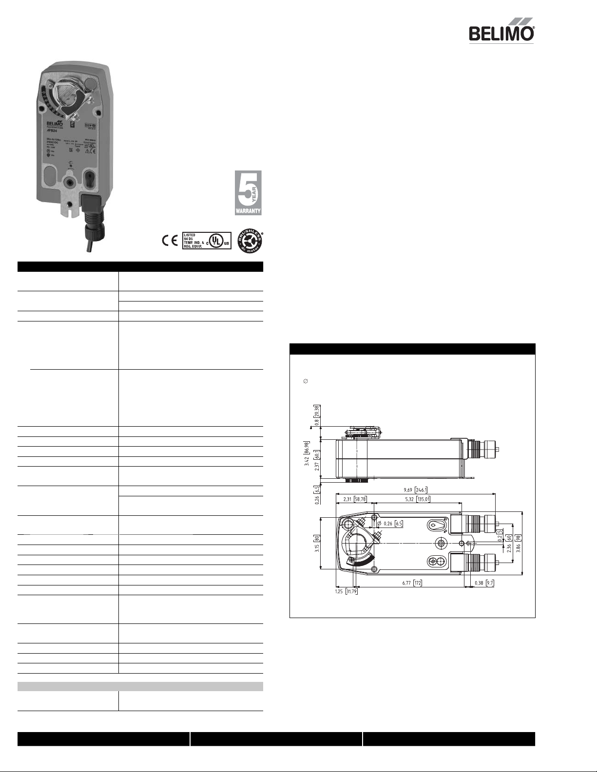
AFB24, AFB24-S, AFX24, AFX24-S
On/Off, Spring Return, 24 V
Technical Data AFB24, AFB24-S, AFX24, AFX24-S
Power supply 24 VAC ± 20% 50/60 Hz
Power consumption running
Transformer sizing 7.5 VA (class 2 power source)
Electrical connection
AFB24... 3 ft, 18 GA appliance cable, 1/2" conduit
AFX24...
Overload protection electronic throughout 0 to 95° rotation
Control on/off
Torque 180 in-lb [10 Nm] minimum
Direction of rotation spring reversible with CW/CCW mounting
Mechanical angle of rotation 95° (adjustable with mechanical end stop, 35° to
Running time
Position indication visual indicator, 0° to 95°
Manual override 5 mm hex crank (³⁄₁₆" Allen), supplied
Humidity max. 95% RH non-condensing
Ambient temperature -22°F to 122°F [-30°C to 50°C]
Storage temperature -40°F to 176°F [-40°C to 80°C]
Housing Nema 2, IP54, Enclosure Type2
Housing material zinc coated metal and plastic casing
Agency listings
† cULus acc. to UL60730-1A/-2-14,
Noise level <50dB(A) motor @ 75 seconds
Servicing maintenance free
Quality standard ISO 9001
Weight 4.6 lbs (2.1 kg); 4.9 lbs (2.25 kg) with switches
† Rated Impulse Voltage 800V, Type of action 1.AA (1.AA.B for -S version), Control Pollution Degree 3.
AFB24-S, AFX24-S
Auxiliary switches 2 x SPDT 3A (0.5A) @ 250 VAC, UL approved
24 VDC +20% / -10%
5 W
holding
2.5 W
connector
-S models: two 3 ft, 18 gauge appliance cables
with 1/2” conduit connectors
3 ft [1m], 10 ft [3m] or 16 ft [5m] 18 GA
appliance or plenum cables, with or without 1/2”
conduit connector
-S models: two 3 ft [1m], 10 ft [3m] or
16 ft [5m] appliance cables, with or without 1/2"
conduit connectors
95°)
motor
< 75 seconds
spring
20 seconds @ -4°F to 122°F [-20°C to 50°C];
< 60 seconds @ -22°F [-30°C]
(0° is full spring return position)
CAN/CSA E60730-1:02, CE acc. to
2004/108/EC & 2006/95/EC
≤62dB(A) spring return
one set at +10°, one adjustable 10° to 90°
Torque min. 180 in-lb, for control of air dampers
Application
For On/Off, fail-safe control of dampers in HVAC systems. Actuator sizing should be
done in accordance with the damper manufacturer’s specifications. Control is On/Off
from an auxiliary contact, or a manual switch.
The actuator is mounted directly to a damper shaft up to 1.05” in diameter by means
of its universal clamp. A crank arm and several mounting brackets are available for
applications where the actuator cannot be direct coupled to the damper shaft.
Operation
The AFB and AFX series actuators provide true spring return operation for reliable failsafe application and positive close off on air tight dampers. The spring return system
provides constant torque to the damper with, and without, power applied to the
actuator.
The AFB and AFX series provides 95° of rotation and is provided with a graduated
position indicator showing 0° to 95°.
The actuator may be stalled anywhere in its normal rotation without the need of
mechanical end switches.
The AFB24-S and AFX24-S versions are provided with two built-in auxiliary switches.
These SPDT switches are provided for safety interfacing or signaling, for example, for
fan start-up. The switching function at the fail-safe position is fixed at +10°, the other
switch function is adjustable between +10° to +90°. The AFB24, AFB24-S, AFX24 and
AFX24-S actuator is shipped at +5° (5° from full fail-safe) to provide automatic
compression against damper gaskets for tight shut-off.
Dimensions (Inches [mm])
K7-2 (supplied)
1/2" Centered
(Default)
3/4" Centered
(Field Selectable)
1.05" Centered
(Field Selectable)
WAFBNFBDim
06/10 - Subject to change. © Belimo Aircontrols (USA), Inc.
800-543-9038 USA 866-805-7089 CANADA 203-791-8396 LATIN AMERICA
2
Page 2
9
A
FBUP, AFBUP-S, AFXUP, AFXUP-
S
Torq
n
F
d
f
T
.
O
n
T
s
p
.
T
p
T
.
T
T
-
u
j
A
c
.
P
pply
0%
n
r
W
g
3
W
T
)
C
C
Elec
on
AFBUP...
3
connector
w
s
3
r
condu
s
O
n
C
O
T
m
D
n
g
r
/CC
g
n
)
R
otor
sec
s
]
Positi
vi
°
(
)
de
5
(
³⁄₁₆
d
y
g
Ambi
C]
e
C]
g
A
08/EC & 2006/95/EC
el
s
d
9001
S
d
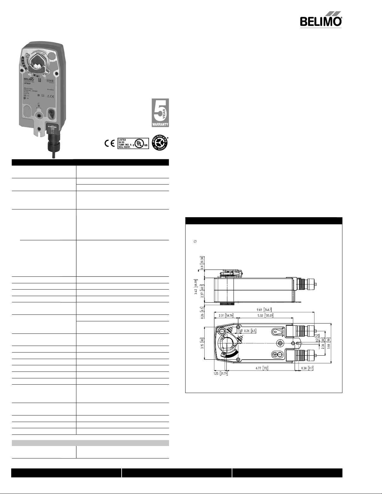
On/Off, Spring Return, 24 to 240 VAC
Technical Data AFBUP, AFBUP-S, AFXUP, AFXUP-S
ower su
Power consumptio
ransformer sizing 7 VA @ 24 VAC (class 2 power source
trical connecti
AFXUP...
verload protectio
ontrol
orque 180 in-lb [20 Nm] minimu
irection of rotatio
Mechanical angle of rotatio
unning time
on indication
Manual overri
umidit
ent temperature -22°F to 122°F [-30°C to 50°
torage temperatur
ousing Nema 2, IP54, Enclosure Type2
ousing material Zinc coated metal and plastic casin
gency listings † cULus acc. to UL60730-1A/-2-14,
lev
ervicing maintenance free
uality standar
eight 4.6 lbs (2.1 kg), 4.9 lbs (2.25 kg) with switches
Rated Impulse Voltage 4kV, Type of action 1.AA (1.AA.B for -S version), Control Pollution Degree 3.
AFBUP-S, AFXUP-
Auxiliary switches 2 x SPDT 3A (0.5A) @ 250 VAC, UL Approve
24...240 VAC -20% / +10%, 50/60 Hz
24...125 VDC ±1
unning
7
holdin
.5
8.5 VA @ 120 VA
18 VA @ 240 VA
ft, 18 GA appliance cable, 1/2" conduit
-S models: Two 3 ft, 18 gauge appliance cables
ith 1/2” conduit connector
ft [1m], 10 ft [3m] or 16 ft [5m] 18 GA
appliance cable, with or without 1/2” conduit
connecto
-S models: Two 3ft [1m], 10 ft [3m] or
16 ft [5m] appliance cables with or without 1/2"
it connector
Electronic throughout 0 to 95° rotation
n/Off
sprin
eversible with CW
95° (adjustable with mechanical end stop, 35° to
95°
m
< 75
pring
20 sec @ -4°F to 122°F [-20°C to 50°C];
< 60 sec @ -22°F [-30°C
sual indicator, 0° to 95
0° is full spring return position
mm hex crank
max. 95% RH non-condensin
-40°F to 176°F [-40°C to 80°
AN/CSA E60730-1:02, CE acc. to
2004/1
<50dB(A) motor @ 75 second
≤62dB(A) spring return
ISO
one set at +10°, one adjustable 10° to 90°
W mountin
Allen), supplie
ue min. 180 in-lb, for control of air dampers
Applicatio
or On/Off, fail-safe control of dampers in HVAC systems. Actuator sizing should be
one in accordance with the damper manufacturer’s specifications. Control is On/Off
rom an auxiliary contact, or a manual switch.
he actuator is mounted directly to a damper shaft up to 1.05” in diameter by means
of its universal clamp. A crank arm and several mounting brackets are available for
applications where the actuator cannot be direct coupled to the damper shaft
peratio
he AFB and AFX series actuators provide true spring return operation for reliable fail-
afe application and positive close off on air tight dampers. The spring return system
rovides constant torque to the damper with, and without, power applied to the
actuator
he AFB and AFX series provides 95° of rotation and is provided with a graduated
osition indicator showing 0° to 95°.
he actuator may be stalled anywhere in its normal rotation without the need of
mechanical end switches
he AFBUP-S and AFXUP-S versions are provided with two built-in auxiliary switches.
hese SPDT switches provide safety interfacing or signaling, for example, for fan start
p. The switching function at the fail-safe position is fixed at +10°, the other switch
function is ad
FXUP-S actuator is shipped at +5° (5° from full fail-safe) to provide automatic
ompression against damper gaskets for tight shut-off
Dimensions (Inches [mm])
ustable between +10° to +90°. The AFBUP, AFBUP-S, AFXUP and
K7-2 (supplied)
1/2" Centered
(Default)
3/4" Centered
(Field Selectable)
1.05" Centered
(Field Selectable)
WAFBNFBDim
M40024 - 05/10 - Subject to change. © Belimo Aircontrols (USA), Inc.
1
800-543-9038 USA 866-805-7089 CANADA 203-791-8396 LATIN AMERICA
Page 3
0
AFBUP, AFBUP-S, AFXUP, AFXUP-S
AV
s
S
06
ch
00
t
t
8
III or IV or Johnson
s
l)
)
60
g
300
g
.
!
.
.
-
Live Electrical Components!
.
(
)
P
(
)
S
A
S
j
g
(
)
On/Off, Spring Return, 24 to 240 VAC
Accessories
8-25
-
7-2 Universal clamp for up to 1.05” dia jackshaft
-
F-CC U
l-
-1
-101
G-11
-AFB
-AFB118
S-100
-150
-2
-
ote: When using AFBUP, AFBUP-S, AFXUP, AFXUP-S actuators, only use accessories listed on
this page.
or actuator wiring information and diagrams, refer to Belimo Wiring Guide.
haft extension
Damper position indicator
rank arm
onduit fitting
mm and 10 mm wren
Universal mounting bracke
niversal mounting bracke
Mounting bracket for Barber ColmanMA 3../4.., Honeywell
Series 100 replacement or new crank
arm type installation
rank arm adaptor kit
rank arm adaptor kit
eather shield (meta
eather shield (polycarbonate
Explosion-proof housin
NEMA 4X housin
Typical Specification
On/Off spring return damper actuators shall be direct coupled type which require
o crank arm and linkage and be capable of direct mounting to a jackshaft up to a
1.05” diameter. The actuators must be designed so that they may be used for either
clockwise or counterclockwise fail-safe operation. Actuators shall be protected
from overload at all angles of rotation. If required, two SPDT auxiliary switch shall
e provided having the capability of one being adjustable. Actuators with auxiliary
switches must be constructed to meet the requirements for Double Insulation so
an electrical ground is not required to meet agency listings. Actuators shall be
cULus approved and have a 5 year warranty, and be manufactured under ISO 9001
nternational Quality Control Standards. Actuators shall be as manufactured by
elimo.
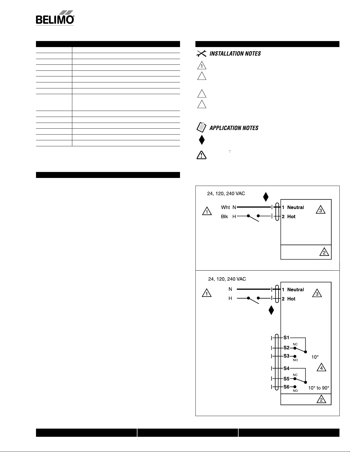
Wiring Diagrams
Provide overload protection and disconnect as required
AUTION Equipment Damage
Actuators may be connected in parallel.
Power consumption and input impedance must be observed.
No ground connection is required
For end position indication, interlock control, fan startup, etc.,
AFBUP-S and AFXUP-S incorporates two built-in auxiliary switches: 2 x
SPDT, 3A (0.5A) @250 VAC, UL Approved, one switch is fi xed at +10°, one
s adjustable 10° to 90°
Meets cULus requirements without the need of an electrical ground con
nection.
During installation, testing, servicing and troubleshooting of this product, it may be
necessary to work with live electrical components. Have a qualifi ed licensed electrician or other
individual who has been properly trained in handling live electrical components perform these
tasks. Failure to follow all electrical safety precautions when exposed to live electrical components could result in death or serious injury
UP
X
066_AFB
AFBUP, AFBUP-S
AFXUP, AFBUP-S
, Inc.
USA
On/Off wiring for AFBUP, AFXU
Wht
UPX
067_AFB
Blk
e. © Belimo Aircontrols
ect to chan
M40024 - 05/10 - Sub
AFBUP-S
AFXUP-S
uxiliary Switches for AFBUP-S, AFXUP-
800-543-9038 USA 866-805-7089 CANADA 203-791-8396 LATIN AMERICA
2
Page 4
AFB24-MFT, AFB24-MFT-S, AFX24-MFT, AFX24-MFT-
S
b
)
)
n
A
n
)
.
N
n
f
.
g
.
A
AFBNFBDim
ly
z
%
r
lding
W
g
)
n
r
AFX...
3
ft [1m]
tors
n
)
e
)
l
x
e
)
f
g
l
*
)
]
)
A
n
)
*
%
%
n
°
)
Allen)
d
g
Ambi
e
)
e
C)
2
g
l
t
dB(A)
A
/CS
1
g
ee
h
g
S
A
s
d
.
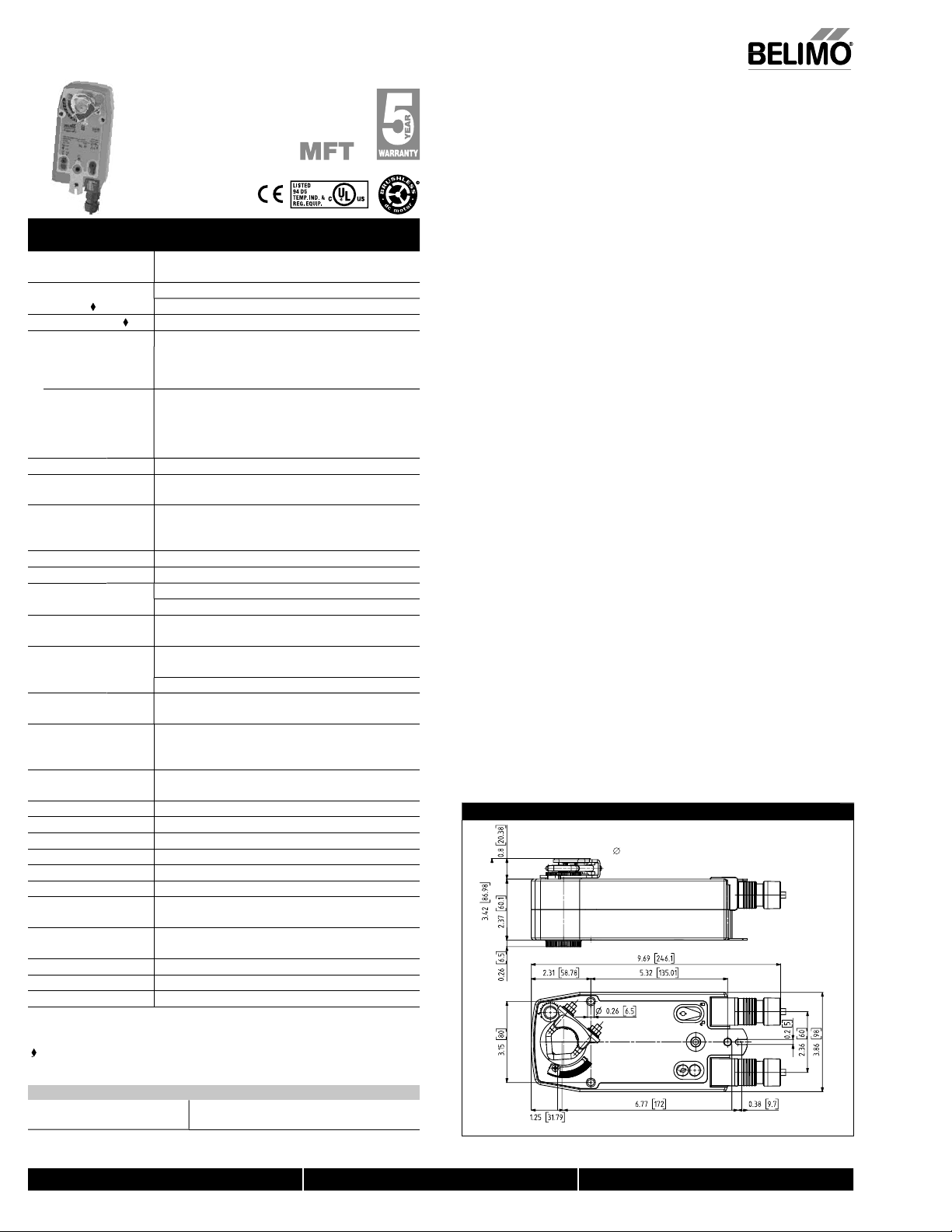
Proportional, Spring Return, 24 V, Multi-Function Technology
Torque min. 180 in-l
Control 2 to 10 VDC (DEFAULT
Feedback 2 to 10 VDC (DEFAULT
Applicatio
or proportional modulation of dampers and control valves in HVAC systems. The
FB24-MFT, AFX24-MFT provides mechanical spring return operation for reliable failafe application.
Technical Data AFB24-MFT, AFB24-MFT-S,
AFX24-MFT, AFX24-MFT-S
ower supp
owe
onsumption
ransformer sizin
ectrical connectio
FB..
verload protectio
Operating range Y* 2 to 10 VDC, 4 to 20 mA (default
nput impedanc
eedback output U* 2 to 10 VDC, 0.5 mA ma
orqu
Direction o
rotation*
echanica
angle of rotation
unning time
ngle of Rotation
adaptatio
Override control
osition indicatio
anual override
umidity
ent temperatur
torage temperatur
ousing NEMA 2, IP54, Enclosure Type
ousing material zinc coated metal and plastic casin
oise leve
gency listings
Quality standard ISO 900
Servicin
eight 4.6 lbs. (1.9 kg), 4.9 lbs. (2 kg) with switc
* Variable when configured with MFT options
Rated Impulse Voltage 800V, Type of action 1.AA (1.AA.B for -S version), Control Pollution Degree 3.
Programmed for 70 sec motor run time. At 150 sec motor run time, transformer sizin
24 VAC, +/- 20%, 50/60 H
24 VDC, +20% / -10
running
.5 W
o
0 VA (Class 2 power source
ft, 18 GA appliance cable, 1/2" conduit connecto
-S models: two 3 ft, 18 gauge appliance cables with
2” conduit connectors
ft [1m], 10 ft [3m] or 16 ft [5m] 18 GA appliance or
lenum cables, with or without 1/2” conduit connector
-S models: two
, 10 ft [3m] or
6 ft [5m] appliance cables with or without 1/2" conduit
connec
lectronic throughout 0 to 95° rotation
variable (VDC, PWM, floating point, on/off)
00 k for 2 to 10 VDC (0.1 mA
00
for 4 to 20 mA
for PWM, floating point and on/off contro
nimum 180 in-lb (20 Nm
pringeversible with cw/ccw mountin
otoreversible with built-in switch
95° (adjustable with mechanical end stop, 35° to 95°
pring<20 sec @ -4°F to 122°F [-20° C to 50° C];
<60 sec @ -22°F [-30° C
motor*50 seconds (default), variable (70 to 220 seconds
off (default
n position = 0%
id. position = 50
ax. position = 100
visual indicator, 0° to 95
0° is spring return position
mm hex crank (₁₆
, supplie
ax. 95% RH, non-condensin
22 to 122° F (-30 to 50° C
40 to 176° F (-40 to 80°
40dB(A) motor @ 150 seconds, run time dependen
≤62
spring return
cULus acc. to UL60730-1A/-2-14, CAN
:02, CE acc. to 2004/108/EC & 2006/95/EC
intenance fr
A E60730-
efault/Configuratio
Default parameters for 2 to 10 VDC applications of the AFB24-MFT, AFX24-MFT
ctuator are assigned during manufacturing. If required, custom versions of the
ctuator can be ordered. The parameters noted in the Technical Data table are
riable.
hese parameters can be changed by three means:
Pre-set configurations from Belimo
Custom configurations from Belimo
Configurations set by the customer using the MFT PC tool (version 3.4 or higher
oftware application
Handheld ZTH-GE
peratio
he AFB24-MFT, AFX24-MFT actuator provides 95° of rotation and is provided with a
raduated position indicator showing 0° to 95°. The actuator will synchronize the 0°
mechanical stop or the physical damper or valve mechanical stop and use this point
or its zero position during normal control operations. A unique manual override allows
the setting of any actuator position within its 95° of rotation with no power applied.
his mechanism can be released physically by the use of a crank supplied with the
ctuator. When power is applied the manual override is released and the actuator
rives toward the fail-safe position
he actuator uses a brushless DC motor which is controlled by an Application Specific
ntegrated Circuit (ASIC) and a microprocessor. The microprocessor provides the
ntelligence to the ASIC to provide a constant rotation rate and to know the actuator’s
exact position. The ASIC monitors and controls the brushless DC motor’s rotation and
rovides a Digital Rotation Sensing (DRS) function to prevent damage to the actuator
n a stall condition. The position feedback signal is generated without the need for
mechanical feedback potentiometers usin
nywhere in its normal rotation without the need of mechanical end switches
he AFB24-MFT, AFX24-MFT is mounted directly to control shafts up to 1.05" diameter
y means of its universal clamp and anti-rotation bracket. A crank arm and several
mounting brackets are available for damper applications where the actuator cannot be
irect coupled to the damper shaft. The spring return system provides minimum
pecified torque to the application during a power interruption. The AFB24-MFT,
FX24-MFT actuator is shipped at +5° (5° from full fail-safe) to provide automatic
compression against damper gaskets for tight shut-off.
NOTE: Please see documentation on Multi-Function Technology.
Dimensions (Inches [mm])
DRS. The actuator may be stalled
K7-2 (supplied)
1/2" Centered
(Default)
3/4" Centered
(Field Selectable)
1.05" Centered
(Field Selectable)
M40024 - 05/10 - Subject to change. © Belimo Aircontrols (USA), Inc
AFB24-MFT-S, AFX24-MFT-
uxiliary switche
2 x SPDT 3A (0.5A) @ 250 VAC, UL approve
one set at +10°, one adjustable 10° to 90°
800-543-9038 USA 866-805-7089 CANADA 203-791-8396 LATIN AMERICA
Page 5

AFB24-MFT, AFB24-MFT-S, AFX24-MFT, AFX24-MFT-
S
y
S
VDC/
A
8
l
AV
n
US
g
6
h
00
1
2
t
n
III
n
S
s
B
)
50
)
g
300
g
d.
!
C.
)
.
.
.
.
.
500
dling li
Accessories
8-25
IND-AFB Damper position indicator
K7-2 Universal clamp for up to 1.05” dia jackshafts
TF-CC
ool-0
ZG-1
ZG-10
ZG-10
ZG-118 Mounting bracket for Barber Colma
ZG-AF
ZG-AFB118
ZS-100 Weather shield (metal
ZS-1
ZS-260 Explosion-proof housin
ZS-
NOTE: When using AFB24-MFT, AFB24-MFT-S, AFX24-MFT and AFX24-MFT-S actuators, only use
accessories listed on this page.
For actuator wiring information and diagrams, refer to Belimo Wiring Guide.
Typical Specification
Spring return control damper actuators shall be direct coupled type which require no
rank arm and linkage and be capable of direct mounting to a jackshaft up to a 1.05”
diameter. The actuator must provide proportional damper control in response to a 2 to
10 VDC or, with the addition of a 500
electronic controller or positioner. The actuators must be designed so that they may be
sed for either clockwise or counterclockwise fail-safe operation. Actuators shall use
a brushless DC motor controlled by a microprocessor and be protected from overload
at all angles of rotation. Run time shall be constant, and independent of torque. A 2 to
10 VDC feedback signal shall be provided for position feedback. Actuators shall be
ULus Approved and have a 5 year warranty, and be manufactured under ISO 9001
International Quality Control Standards. Actuators shall be as manufactured by Belimo.
haft extensio
rank arm
onduit fittin
8mm and 10 mm wrenc
Universal mounting bracket
Universal mounting bracket
Multiple actuator mounting bracke
od
or IV or Johnso
arm type installation
rank arm adaptor kit
rank arm adaptor kit
Weather shield (polycarbonate
NEMA 4X housin
eries 100 replacement or new crank
resistor, a 4 to 20 mA control input from an
®
MA 3../4.., Honeywell
Proportional, Spring Return, 24 V, Multi-Function Technolog
AFB24-MFT-S
AFX24-MFT-S
Auxiliary Switches for AFB24-MFT-S, AFX24-MFT-
4-20 m
W600_AFB_AFXW399_08
399_08
Wiring Diagrams
M40024 - 05/10 - Subject to change. © Belimo Aircontrols (USA), Inc.
rovide overload protection and disconnect as require
AUTION
2
Actuators may be connected in parallel if not mechanically mounted to the same
shaft. Power consumption and input impedance must be observed.
Actuators may also be powered by 24 VD
osition feedback cannot be used with Triac sink controller.
The actuator internal common reference is not compatible.
ontrol signal may be pulsed from either the Hot (source
or the Common (sink) 24 VAC line
ontact closures A & B also can be triacs
A & B should both be closed for triac source and open for triac sink
r triac sink the common connection from the actuator
must be connected to the hot connection of the controller
eets UL requirements without the need of an electrical ground
nnection
The ZG-R01
quipment Damage
resistor may be used.
ARNINGLive Electrical Components!
uring installation, testing, servicing and troubleshooting of this product, it may be
necessary to work with live electrical components. Have a qualifi ed licensed electrician
r other individual who has been properly trained in han
perform these tasks. Failure to follow all electrical safety precautions when exposed to
ve electrical components could result in death or serious injury.
ve electrical components
W399_08
W399_0
loating Point contro
800-543-9038 USA 866-805-7089 CANADA 203-791-8396 LATIN AMERICA
22
Page 6

roduct Cross Referenc
e
on
.
urrent to New Generati
Torque
AF120 US, AF120-S US
AF230 US, AF230-S US AFBUP, AFBUP-S, AFXUP, AFXUP-S
133 in-lb [15 Nm] minimum 180 in-lb. [20 Nm] minimum
Running Time
Noise Level
Motor Technology
OPERATION
Overload Protection
Operating Temperature
Operating Humidity
Control Signal
CONTROL
Dimensions (L x W x H)
Motor
Spring
< 75 seconds <75 seconds
< 60 seconds
Max. 45 dB (A)
20 seconds @ -4°F to 122°F [-20°C to 50°C];
<60 seconds @ -22°F [-30°C]
<50dB(A) motor @ 75 seconds;
62dB(A) Spring Return
DC Motor DC Motor
Electronic throughout 0° to 95° rotation Electronic throughout 0° to 95° rotation
-22°F to 122°F [-30°C to 50°C] -22°F to 122°F [-30°C to 50°C]
5 to 95% RH non-condensing 5 to 95% RH, non-condensing
On/Off On/Off
0.65" [16.5]
[57]
2.24"
3.25" [82.7]
0.19" [5]
0.39" [10]
0.35" [9]
2.64"
[67]
10.47" [266]
5.85" [148.5]
0.26" [6.5]
1.93"
[49]
3.86" [98]
3.15" [80]
With Conduit Fitting
Shaft Dimensions
Direction of Rotation
Manual Override
MOUNTING & COMMISSIONING
1.97"
[50]
10.47" [266] x 3.86" [98] x 3.25" [82.7] 9.69" [246] x 3.86" [98] x 3.42" [87]
Up to 1.05” Up to 1.05”
Reversible with CW/CCW mounting Reversible with CW/CCW mounting
3 mm hex crank supplied
5 mm hex crank
(3/16" Allen), supplied
Position Indication
to 95° (0° is Spring
Return position)
95°, adjustable 30
Visual indicator, 0°
Angle of Rotation
to 95° w/ ZDB-AF2
US accessory
Visual indicator, 0° to
95° (0° is Spring
Return position)
M40024 - 05/10 - Subject to change. © Belimo Aircontrols (USA), Inc
95° (adjustable with
mechanical end stop,
35° to 95°)
800-543-9038 USA 866-805-7089 CANADA 203-791-8396 LATIN AMERICA
Page 7

6
Product Cross Referenc
e
n
urrent to New Generatio
Power Supply
Power
Consumption
Transformer Sizing /
VA Rating
Auxiliary Switches
ELECTRICAL WIRING
Electrical Connection
Running
Holding
AF120 US, AF120-S US
AF230 US, AF230-S US
AF120: 120 VAC ± 10% 50/60 Hz
AF230: 230 VAC ± 15% 50/60 Hz
AF120: 8 W
AF230: 8.5 W
AF120, AF230: 3 W 3.5 W
AF120, AF230: 11 VA
(-S Models): 2 x
SPDT 7A (2.5A) @
250 VAC,
UL Approved, one set
at +5°, one adjustable
5° to 85°
3 ft, 18 GA appliance
cable 1/2” conduit
connector,
(-S Models): Two 3 ft,
18 GA, appliance
cables, ½" conduit
connectors
AFBUP, AFBUP-S, AFXUP, AFXUP-S
24…240 VAC -20 %/+10%, 50/60 Hz;
24…125 VDC +/- 10 %
7 W
7 VA @ 24 VAC
8.5 VA @120 VAC
18 VA @ 240 VAC
(-S Models): Two SPDT
3A (0.5A inductive) @
250V UL Approved, one
set at +10°, one
adjustable 10° to 90°
3 ft, 18 GA, appliance
cable, ½" conduit
connector, (-S Models):
Two 3 ft, 18 GA,
appliance cables, ½"
conduit connectors;
Optional 10 or 16 ft
cables with X types
M40024 - 05/10 - Subject to change. © Belimo Aircontrols (USA), Inc.
Housing Rating
Housing Material
Agency Listings
Storage Temperature
CONSTRUCTION
Weight
NEMA 2, IP54 NEMA 2, IP54, Enclosure Type2
Zinc coated steel Zinc coated metal and plastic casing
cULus acc. to UL 873 and CAN/CSA C22.2 No.
24-93
-40°F to 176°F [-40°C to 80°C] -40°F to 176°F [-40°C to 80°C]
7.3 lbs (3.3 kg)
cULus acc. to UL60730-1A/-2-14, CAN/CSA
E60730-1:02, CE acc. to 2004/108/EC &
2006/95/EC
4.6 lbs (2.1 kg), (-S Models): 4.9 lbs (2.25 kg)
800-543-9038 USA 866-805-7089 CANADA 203-791-8396 LATIN AMERICA
2
Page 8

roduct Cross Referenc
e
on
.
urrent to New Generati
Torque
Running Time
Noise Level
Motor Technology
OPERATION
Overload Protection
Operating Temperature
Operating Humidity
Motor
Spring
AF24-MFT US, AF24-MFT-S US
AFB24-MFT, AFB24-MFT-S,
AFX24-MFT, AFX24-MFT-S
133 in-lb. [15 Nm] minimum 180 in-lb. [20 Nm] minimum
150 seconds (default),
variable (75 to 300 seconds)
<20 sec spring return fail safe position
<45 dB (A)
<20 seconds @ -4°F to 122°F [-20°C to 50°C];
40dB(A) motor @ 150 seconds, run time dependant;
150 seconds (default),
variable (70 to 220 seconds)
<60 seconds @ -22°F [-30°C]
62dB(A) spring return
Brushless DC motor Brushless DC motor
Electronic throughout 0 to 95° rotation Electronic throughout 0 to 95° rotation
-22 to 122° F (-30 to 50° C) -22 to 122°F (-30 to 50°C)
5 to 95% RH, non-condensing Max. 95% RH, non-condensing
Operating Range 'Y'
Input Impedance
CONTROL
Feedback Output 'U'
Dimensions (L x W x H)
With Conduit Fitting
Shaft Dimensions
2 to 10 VDC, 4 to 20 mA w/500 ȍ resistor;
Programmable Variable
100 kȍ for 2 to 10 VDC (0.1 mA); 500 ȍ
for 4 to 20 mA; 1500 ȍ for PWM,
Floating Point and On/Off
2 to 10 VDC, 0.5 mA max, variable when
configured with MFT options
0.65" [16.5]
[57]
2.24"
3.25" [82.7]
0.19" [5]
0.39" [10]
0.35" [9]
3.86" [98]
3.15" [80]
1.97"
[50]
2.64"
[67]
10.47" [266]
5.85" [148.5]
0.26" [6.5]
1.93"
[49]
2 to 10 VDC, 4 to 20 mA w/500 ȍ resistor;
Variable (VDC, PWM, Floating Point, On/Off)
100 kȍ for 2 to 10 VDC (0.1 mA); 500 ȍ for 4 to 20 mA;
1500 ȍ for PWM, Floating Point, On/Off
2 to 10 VDC, 0.5mA max,
variable when configured with MFT options
10.47" [266] x 3.86" [98] x 3.25" [82.7] 9.69" [246] x 3.86" [98] x 3.42" [87]
Up to 1.05" Up to 1.05"
Direction of
Rotation
Motor
Reversible with
built-in switch
MOUNTING & COMMISSIONING
Spring
Manual Override
Reversible with CW/CCW mounting Reversible with CW/CCW mounting
3 mm hex crank (supplied)
Reversible with built-in
switch
5 mm hex crank
(3/16" Allen),
supplied
M40024 - 05/10 - Subject to change. © Belimo Aircontrols (USA), Inc
Position Indication
800-543-9038 USA 866-805-7089 CANADA 203-791-8396 LATIN AMERICA
Visual indicator, 0°
to 95° (0° is Spring
Return position)
Visual indicator, 0°
to 95° (0° is Spring
Return position)
Page 9

8
Product Cross Referenc
e
n
urrent to New Generatio
Angle of Rotation
MOUNTING &
COMMISSIONING
Power Supply
Power
Consumption
Transformer Sizing
Auxiliary Switches
ELECTRICAL WIRING
Electrical Connection
Running
Holding
AF24-MFT US, AF24-MFT-S US
95°, adjustable 30 to
95° w/ ZDB-AF2 US
accessory
24 VAC, ± 20%, 50/60 Hz; 24 VDC, ±10% 24 VAC, ± 20%, 50/60 Hz; 24 VDC, +20/-10%
6 W 7.5 W
2.5 W 3 W
10 VA (Class 2 power source) 10 VA (Class 2 power source)*
(-S Models): 2 x
SPDT 7A (2.5A) @
250 VAC,
UL Approved, one set
at +5°, one adjustable
25° to 85°
3 ft, 18 GA appliance
cable 1/2” conduit
connector,
(-S Models): Two 3 ft,
18 GA, appliance
cables, ½" conduit
connectors
Two 3 ft, 18 GA, appliance
connectors; Optional 10 or
models only) with X types
AFB24-MFT, AFB24-MFT-S,
AFX24-MFT, AFX24-MFT-S
95° (adjustable with
mechanical end stop,
35° to 95°)
(-S Models): Two SPDT
3A (0.5A inductive) @
250V UL Approved, one
set at + 10°, one
adjustable 10° to 90°
3 ft, 18 GA, appliance
cable, ½" conduit
connector, (-S Models):
cables, ½" conduit
16 ft cables and plenum
rated cables (non -S
Housing Rating
Housing Material
Agency Listings
Storage Temperature
CONSTRUCTION
Weight
*10 VA @ 70 second run time
8.5 VA @ 150 second run time
8 VA @ 220 second run time
M40024 - 05/10 - Subject to change. © Belimo Aircontrols (USA), Inc.
800-543-9038 USA 866-805-7089 CANADA 203-791-8396 LATIN AMERICA
NEMA 2, IP54 NEMA 2, IP54, Enclosure Type2
Zinc coated metal Zinc coated metal and plastic casing
cULus acc. to UL 873 and
CAN/CSA C22.2 No. 24-93
-40 to 176° F (-40 to 80° C) -40 to 176°F (-40 to 80°C)
6.0 lbs. (2.7 kg)
cULus acc. to UL60730-1A/-2-14, CAN/CSA
E60730-1:02, CE acc. to 2004/108/EC &
2006/95/EC
4.6 lbs. (2.1 kg), (-S Models): 4.9 lbs.(2.25 kg)
2
Page 10

roduct Cross Referenc
e
on
.
urrent to New Generati
Torque
Running
Time
Noise Level
Motor Technology
OPERATION
Overload Protection
Operating Temperature
Operating Humidity
Operating Range 'WRB'
Motor
Spring
AF24-MFT95 US AFB24-MFT95, AFX24-MFT95
133 in-lb. [15 Nm] minimum 180 in-lb. [20 Nm] minimum
150 seconds (default), variable (75 to 300
seconds)
<20 sec spring return fail safe position
<45 dB (A)
Brushless DC motor Brushless DC motor
electronic throughout 0 to 95° rotation Electronic throughout 0 to 95° rotation
-22 to 122° F (-30 to 50° C) -22 to 122°F (-30 to 50°C)
5 to 95% RH, non-condensing Max. 95% RH, non-condensing
0 to 135 Honeywell electronic series 90,
or a 0 to 135 input
150 seconds (default), variable (70 to 220
seconds)
<20 sec @ -4°F to 122°F [-20°C to 50°C]; <60
sec @ -22°F [-30°C]
40dB(A) motor @ 150 seconds, run time
dependant; 62dB(A) spring return
0 to 135 Honeywell electronic series 90,
or a 0 to 135 input
Feedback Output 'U'
CONTROL
Dimensions
(L x W x H) [mm]
With Conduit Fitting
Shaft Dimensions
Direction of
Rotation
MOUNTING & COMMISSIONING
Motor
Spring
2 to 10 VDC, 0.5mA max, Variable when
configured with MFT options
0.65" [16.5]
[57]
2.24"
3.25" [82.7]
0.19" [5]
0.39" [10]
0.35" [9]
3.86" [98]
3.15" [80]
1.97"
[50]
2.64"
[67]
10.47" [266]
5.85" [148.5]
0.26" [6.5]
1.93"
[49]
2 to 10 VDC, 0.5mA max, Variable when
configured with MFT options
10.47" [266] x 3.86" [98] x 3.25" [82.7] 9.69" [246] x 3. 86" [98] x 3.42" [87]
up to 1.05" up to 1.05"
Reversible with built-in
switch
Reversible with built-in
switch
Reversible with CW/CCW mounting Reversible with CW/CCW mounting
Manual Override
Position Indication
Visual indicator, 0°
3 mm hex crank (supplied)
to 95°
(3/16" Allen),
supplied
M40024 - 05/10 - Subject to change. © Belimo Aircontrols (USA), Inc
Visual indicator, 0°
to 95° (0° is Spring
Return position)
5 mm hex crank
800-543-9038 USA 866-805-7089 CANADA 203-791-8396 LATIN AMERICA
Page 11

G
Product Cross Referenc
e
n
urrent to New Generatio
AF24-MFT95 US AFB24-MFT95, AFX24-MF T95
Angle of Rotation
MOUNTING &
COMMISSIONIN
Power Supply
Power
Consumption
Transformer Sizing
Auxiliary Switches
ELECTRICAL WIRING
Electrical Connection
Housing Rating
Housing Material
Running
Holding
95°, adjustable 30 to
95° w/ ZDB-AF2 US
accessory
24 VAC, ± 20%, 50/60 Hz; 24 VDC, ±10%
6 W
2 W
95° (adjustable with
mechanical end stop,
35° to 95°)
24 VAC, ± 20%, 50/60 Hz;
24 VDC, +20/-10%
7.5 W
3 W
10 VA (Class 2 power source) 10 VA (Class 2 power source)*
N/A N/A
3 ft, 18 GA, plenum
cable, ½" conduit
3 ft, 18 GA appliance
cable, 1/2” conduit
connector
connector; AFX
Model: 3 ft, 18 GA,
plenum rated cable
with or without 1/2"
conduit connector
NEMA 2, IP54 NEMA 2, IP54, Enclosure Type2
Zinc coated metal Zinc coated metal and plastic casing
Agency Listings
CONSTRUCTION
Storage Temperature
Weight
* 10 VA @ 70 second run time
8.5 VA @ 150 second run time
8 VA @ 220 second run time
M40024 - 05/10 - Subject to change. © Belimo Aircontrols (USA), Inc.
cULus acc. to UL 873 and
CAN/CSA C22.2 No. 24-93
-40 to 176° F (-40 to 80° C) -40 to 176°F (-40 to 80°C)
6.0 lbs. (2.7 kg) 4.6 lbs. (2.1 kg)
cULus acc. to UL60730-1A/-2-14,
CAN/CSA E60730-1:02, CE acc. to
2004/108/EC & 2006/95/EC
800-543-9038 USA 866-805-7089 CANADA 203-791-8396 LATIN AMERICA
 Loading...