

Page 1
SERIES 14 INSTALLATION INSTRUCTIONS
and field service check list
A1014L1 Amplifier /
A1014 Amplifier
AD1014/AD1014L1
Amplifier-Selectors
Table of Contents
Page 2 Introduction and Dimensions
Page 3 Specifications
Installation of Components
Page 4 & 5 Field Service Checklist
Page 6 Preliminary Circuit Analysis
Low Fire Start Time Adjustment
Sensitivity Adjustment
Page 7 Wiring Diagrams
Page 8 Temperature Calibration
Valve Adjustments
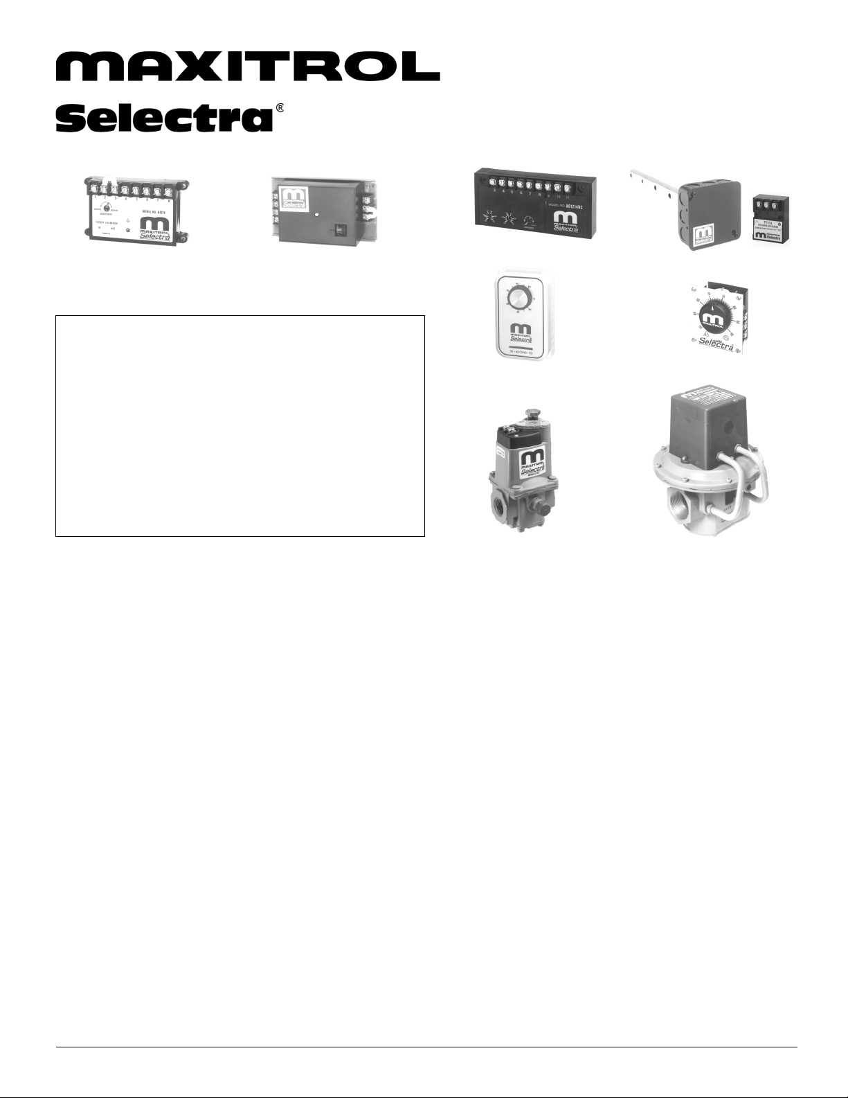
System Components
Amplifiers:
A1014 (use with all temperature ranges)
A1014L1 (all ranges - adjustable low fire start duration)
Amplifier-Selectors: (with integral temperature dial)
AD1014-4080 (40° to 80° F)
AD1014-5590 (55° to 90° F)
AD1014-1116 (110° to 160° F)
AD1014-1621 (160° to 210 ° F)
AD1014L1-4080 (40° to 80° F - adjustable low fire start duration)
AD1014L1-5590 (55° to 90° F - adjustable low fire start duration)
AD1014L1-1116 (110° to 160° F - adjustable low fire start duration)
AD1014L1-1621 (160° to 210° F - adjustable low fire start duration)
Dual Temperature Amplifier-Selectors:
AD1214__ (integral dual selector - any comb. of 2 standard ranges avail.)
Example - AD1214BC (120° to 170° F and 160° to 210° F, use w/TS214BC
Example - AD1214AD (80° to 130° F and 200° to 250° F, use w/TS214AD
Remote Temperature Selectors:
TD114 (55° to 90° F w/override 0° to 40° over set point)
TD114A (80° to 130° F)
TD114A-1 (80° to 130° F w/ override 0° to 40° F over set point)
TD114B (120 to 170° F)
TD114C (160° to 210° F)
TD114D (200° to 250° F)
TD114E (100° to 250° F)
TD114F (40° to 80° F w/override 0° to 40° over set point)
TD114G (90° to 140° F)
TD114-1 (55° to 90° F w/120° to 170° F override) * use w/TS114
TD114-2 (55° to 90° F w/two outputs)
TD114G-2 (90° to 140° F w/two outputs)
NOTE: Remote Selector and Discharge Temperature Sensor must have same
temperature range to be compatible.
Optional: ETD-1 enclosure, EFP-1 cover plate only - no enclosure
Discharge Air Temperature Sensors: use with Mixing Tube
TS114 (55° to 90° F)
TS114A (80° to 130° F)
TS114B (120° to 170° F)
TS114C (160° to 210° F)
TS114D (200° to 250° F)
TS114E (100° to 250° F)
TS114F (40° to 80° F)
©2007 Maxitrol Company, All Rights Reserved
AD1214 Amplifier
Override Stat
Mixing Tube and Sensor
Remote Temperature Selector
Valves
TS114G (90° to 140° F)
TS114J (110° to 160° F) To be used w/ AD1014-1116
TS214__ (dual sensor - any combination of 2 standard ranges available)
Example - TS214G (55° to 90° F and 90° to 140° F, use w/TD114 & TD114G,
Example - TS214AD (80° to 130° F and 200° to 250° F, use w/TD114A &
Mixing Tubes: use with Sensors
MT1-9 or 2-9 (9" length)
MT1-12 or 2-12 (12" length)
MT1-23 or 2-23 (23" length)
MT1-28 or 2-28 (28" length)
MT1-57 (57" length)
Valves:
M411 (3/8" & 1/2" pipe size)
M511 (1/2" & 3/4" pipe size)
M611 (3/4" & 1" pipe size)
MR212D (1", 1-1/4", 1-1/2" pipe size)
MR212E (1-1/2" & 2" pipe size)
MR212G (2-1/2" & 3" pipe size)
MR212J (4" flanged)
MR212-2D, E, G, J (same as above except used for 2-speed blower or dual fuel
operation)
NOTE: M (Modulator) valve requires a pressure regulator for high fire setting. MR
(Modulator-Regulator) valve requires no pressure regulator up to 5 psi.
Optional:
Dual Temperature Selector:
DOOR HEATERS TD114HD use w/TS114 (door closed 55° to 90° F/open 90° to 140° F)
PAINT SPRAY BOOTHS OR OTHER DUAL APPLICATIONS TD214__ (dual selector w/switch - any comb. of 2 standard ranges avail.)
Example - TD214G (55° to 90° F [spray] and 90° to 140° F [dry], use w/TS214G
Example - TD214AD (80° to 130° F and 200° to 250° F, use w/TS214AD
TD214__X (same as TD214__, less enclosure)
Inlet Air Temperature Sensors: use with Mixing Tube
TS10765A (8:1 ratio)
TS10765B (5:1 ratio)
TS10765C (3.5:1 ratio)
Override Stat: (use only with TD114, F ,-1, A-1)
T115 (40° to 90° F)
1
or TD214G [selector w/switch], or AD1214G)
TD114D, or TD214AD [selector w/ switch], or AD1214AD)
Page 2
Introduction and Dimensions
Selectra SERIES 14 electronic gas flame modulation
systems are designed primarily for make-up air heating, as
components of direct fired equipment. They may be field
installed on existing equipment or specified for new
equipment installation. Natural, manufactured, mixed, LP
and LP gas air mixture are compatible gases.
The systems utilize Modulator or Modulator-Regulator
valves. Amplifiers are available with adjustable low-fire
start duration, and with integral or remote temperature
selection. A discharge air temperature sensor is mounted
within a mixing tube housing.
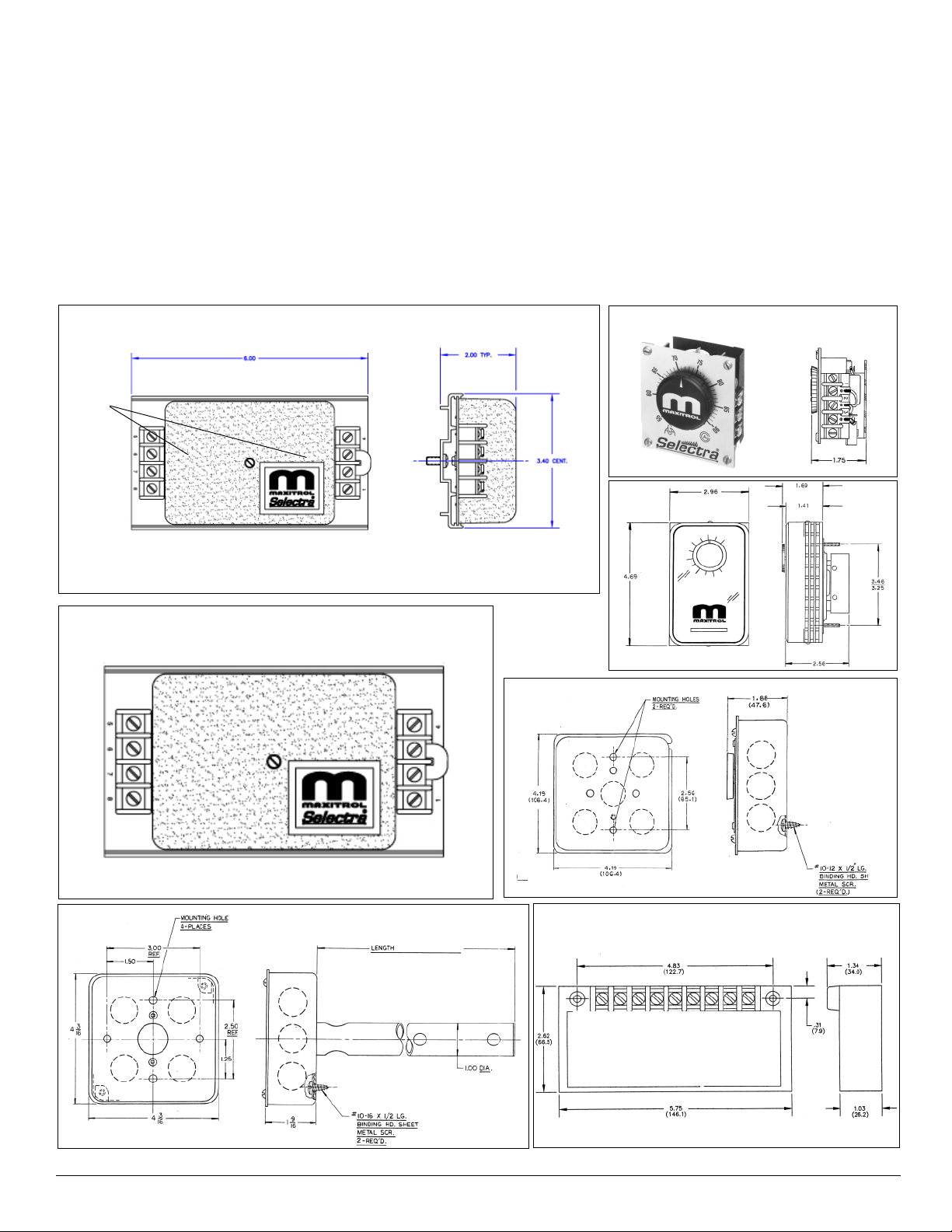
MOUNTING
HOLES
A1014L1,
AD1014,
AD1014L1
Optional - a room override thermostat provides space
temperature control by raising the discharge air temperature
to a pre-selected point - when used in conjunction with the
remote temperature selector.
Optional - an inlet air sensor (and mixing tube) provides
inverse change in discharge air for each degree change in
inlet air - when installed in a convenient duct location
upstream of the burner.
Optional - a dual temperature selector replaces TD114 to
provide dual control for door heaters, or other applications
such as paint spray booths (TD214_ or _X, or AD1214_).
TD114
T115
A1014
(AD models have integrated temperature dial in
lower right corner, logo label in upper left corner)
(SEE PAGE 1)
ETD-1
AD1214
©2007 Maxitrol Company, All Rights Reserved
MIXING TUBES
2
Page 3
Specifications
Power Requirements: 24 VAC, 50/60 Hz Class II transformer
NOTE: Transformer secondary must not be grounded in any
portion of the circuit external to a Maxitrol amplifier. If existing
transformer is grounded, a separate isolated transformer
must be used. Electrical interference may effect
performance and/or damage equipment.
Ambient Limits:
Operating.....-40
Non-operating.....-50
Gases: Suitable for application in natural, manufactured, mixed
gases, liquefied petroleum gases and LP Gas Air Mixture piping
systems.
Vent: M411, 511, 611.....vertical vent outlet 1/8" NPT - 12A06
installed
MR212.....two vents located in upper housing, both equipped
o
to 125o F / -40o to 52o C
o
to 185o F / -46o to 85o C
Installation of Components
Control wires connected to the Override Stat, Discharge
Air Sensor, or Remote Temperature Selector must not
be run close to or inside conduit with power or ignition
wires. Doing so may cause the unit to function
erratically or may destroy the amplifier. If shielded
wires are used, shield must be insulated and grounded
at the amplifier location only.
with vent limiting means
Pressure Limits:
Maximum Discharge Pressure (M411, 511, 611).....7" w.c. /
17 mbar
Static Pressure Rating (M411, 511, 611).................5.0 psi /
345 mbar
Maximum Operating Inlet Pressure
M411, 511, 611.....1 psi / 70 mbar
MR212.....5.0 psi / 345 mbar
Maximum Emergency Exposure*
M411, 511, 611.....3.0 psi / 210 mbar
MR212.....12.5 psi / 862 mbar
* May not function properly at this pressure, but will suffer
no internal damage
Remote (or Dual) Selector: Install in control cabinet or
other chosen location. NOTE: Suffix letters must match,
e.g. TS114A must be used with TD114A. For wiring runs
longer than 200 ft. substitute ES261-1/ES261-2 for TD114.
The ES261s are a 2-piece version of the TD114. ES261-1
is a temperature setting dial only, ES261-2 must be
mounted at furnace location.
Wiring Run: If control wiring is inside conduit with
line voltage wiring, use shielded cable up to 100 ft.
For best results up to 200 ft., run control wiring in
separate conduit. For longer runs see Remote
Selector below.
Discharge Temperature Sensor / Mixing Tube
Assembly: sensor housed in mixing tube, install in
discharge air stream.
Optional:
Dual Temperature Selector: see preceding Remote/Dual
selector.
Amplifier / Amplifier-Selector: contains the wiring
terminals and sensitivity adjustment - install in any
convenient location that is protected from the weather and
contaminated atmosphere.
Room Override Stat: mount in heated area not in direct
path of discharge air stream.
Inlet Air Sensor: install in convenient location upstream of
burner, in intake air duct.
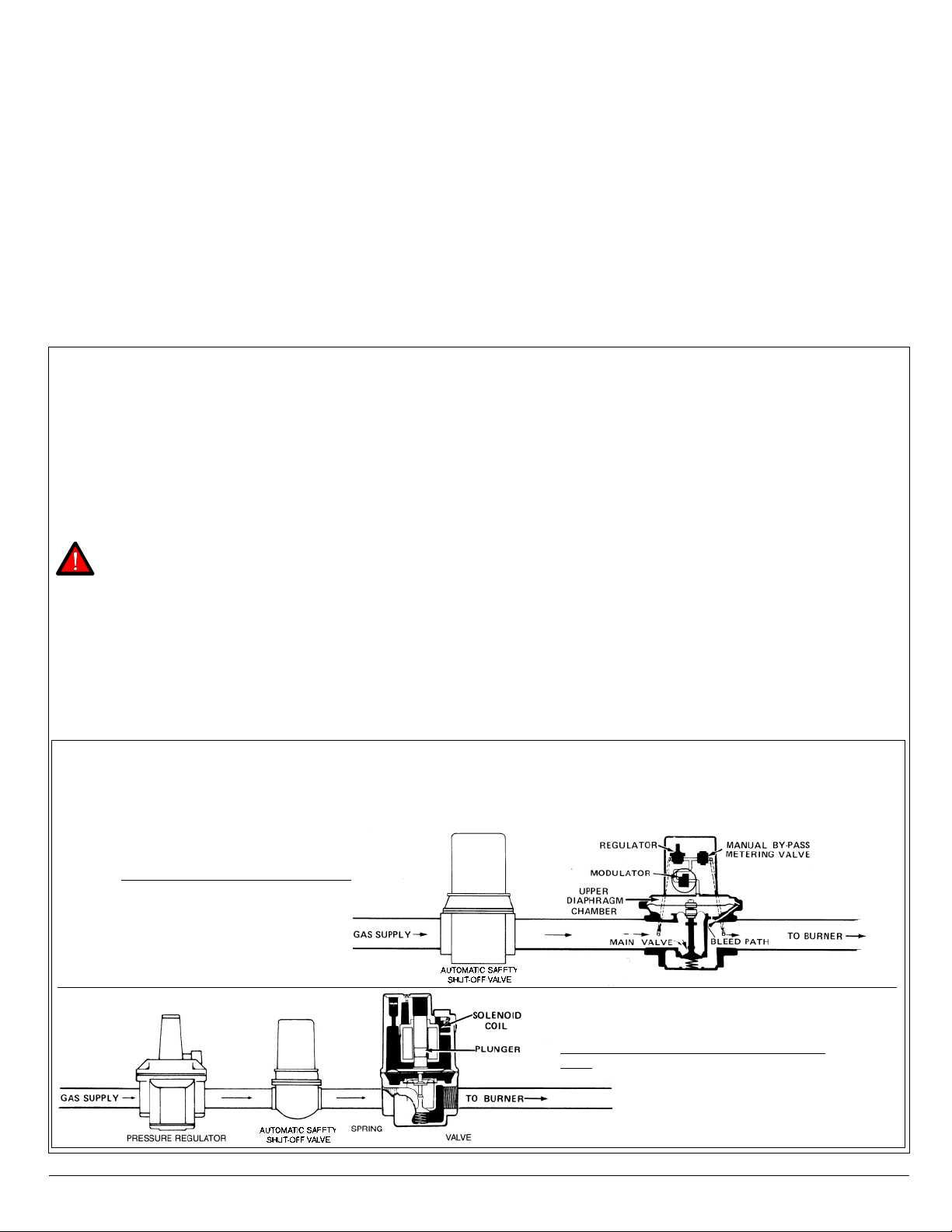
Typical Gas Trains
Modulator (M) or Modulator-Regulator (MR) Valve: Mount in upright position in horizontal run of pipe, downstream of
other controls - a separate gas pressure regulator must be used with any modulator (M) valve.
MR Valve: Modulator-regulator valve
©2007 Maxitrol Company, All Rights Reserved
M Valve: Regulator upstream of modulator
valve
3
Page 4

1. Install properly.
FIELD TEST REMEDY
necessary.
2. Prove the power source.
3. Tighten connections or replace wiring.
4. If modulating voltages are obtained, Check TS114 circuit for shorts. Replace TS114 if
for MR212 Valve.
may be assumed faulty. Replace.
6. Replace modulator head if not approximately 45-55 ohms for M611 Valve and 60-80 ohms
5. If items 2, 3, and 4 check out and modulating voltages are still not obtained, amplifier
7. Clean or replace plunger if necessary. Install as per diagrams page 3.
8. Adjust to proper minimum fire.
9. If reading is greater than 1.5” negative pressure, check for clogged filters or other
TS114/TS10765.
inlet air restrictions. Consult factory for other solutions.
13 . Clean seat. Clean valve or replace if necessary.
10 . Correct wiring if shorts exist.
11. If modulating voltages are obtained, check TS114/TS10765 for open circuits. Replace
14 . Clean, or if necessary, replace plunger.
12 . Correct the wiring.
17 . If flame stabilizes, adjust sensitivity control to maintain an even flame.
18 . If the flame is steady throughout the entire modulating range, the TS114 must be moved.
15 . Increase inlet pressure if possible.
16. See valve adjustments on page 8.
19 . If smooth operation results, isolate effected wiring from source of induced voltage.
amplifier may be assumed faulty. Replace. If erratic operation is noted only over a small
range of 2 or 3 volts, the voltage source may contain surges. Consult Maxitrol.
20. If erratic or unstable D.C. voltages are obtained throughout the modulating range, the
21 . Sensed temperature will vary from TD114 dial settings. This is intentional.
22 . Correct wiring.
23. See calibration procedure.
24. Move TS114 to location where average representative temperature can be sensed.
0
26 . Replace modulator head if less than 40 ohms.
27 . Correct wiring is short is found.
25 . TD114 dial setting, then check thermostat setting and/or check wiring for shorts.
temperature.
28 . Reset to correct temperature.
29 . If on high fire, control can do no more. Heater unable to furnish additional heat to raise
4
outside temperature change from 60
0
, or 8
0
, 5
0
for each 3.5
0
terminals 1 and 2, and TD114 terminals 1 and 3.
outlined.
1. Arrow on side of Valve should point in direction of gas flow.
2. Check for 24V AC at amplifier terminals 7 and 8.
3. Inspect for loose or broken wires between amplifier terminals 1and 2, and TD114
4. Connect test resistor as described in Preliminary Circuit Analysis. Follow procedure
5. Check items 2, 3 and 4.
6. Measure resistance across modulator terminals with connecting wires detached.
POSSIBLE CAUSE
Symptom ‘L’).
1. Modulating valve improperly installed (or see
No gas flow.
SYMPTOM
A.
Field Service Checklist
Selector circuit or wiring.
circuit or wiring.
2. Short circuit or no voltage to the amplifier.
3. Open circuit in TD 114. Remote Temperature
4. Short circuit in TS114, Discharge Air Sensor
5. Faulty amplifier.
6. Short circuit or open circuit in Modulator Coil.
Continuous
Low Fire (electronics
problem).
B.
Continuous Low
C.
Reading should be less than 1.5” w.c. negative pressure.
sleeve.
8. See valve adjustments on page 8.
7. Inspect. Plunger should be installed per diagrams page 3 and operate freely in solenoid
9. Close main gas supply and measure manifold pressure with blower operating.
installed.
8. Incorrect by-pass metering valve adjustment.
7. Plunger missing, jammed or improperly
9. Excessive negative burner pressure.
Fire (electronics OK).
Incorrect Minimum
Fire Erratic or
Pulsating Flame.
D.
in Preliminary Circuit Analysis. Follow procedure outlined.
10 . Inspect for shorts at or between Amplifier terminals 1 and 2 or TD114 terminals 1 and 3.
11 . Check TS114/TS10765 for open internal circuit. Connect test resistor as described
Selector circuit or wiring.
10 . Short circuit in TD114 Remote Temperature
11 . Open circuit in TS114/TS10765. Discharge or
Continuous High
Fire (electronics
problem).
E.
13. Remove bottom plate and inspect valve and seat.
12. Inspect.
Inlet Air Sensor Circuit or wiring.
terminals 2 and 3.
12 . Jumper not connected across amplifier
13. Foreign object holding valve open.
Continuous High
F.
fire. Pressure should be equal to the sum of outlet pressure setting plus pressure drop of
equipment manufacturer.
14 . Inspect. Plunger should be smooth, clean, and operate freely in solenoid sleeve.
15 . Read pressure at inlet to modulating valve using a manometer with unit operating at full
the valve (see Maxitrol Capacity Chart).
17 . Adjust sensitivity control counter-clockwise.
16 . Read manifold pressure using manometer and compare with recommendation of
Pressure Regulator.
14 . Plunger jammed.
15 . Inlet pressure too low.
Fire (electronics OK).
Incorrect Maximum
Fire.
G.
17. Hunting.
16 . Incorrect outlet pressure adjustment of
Erratic or Pulsating
H.
equipment operation.
18 . Connect test resistor as described in Preliminary Circuit Analysis. Turn TD114 selector dial
so heater goes through its entire modulating range.
19 . Temporarily wire each of TD114, TS114, and MR212 externally and observe heater/
circuits causing induced voltages.
18 . Erratic air patterns or improper TS114 location.
19 . Wiring is run next to high voltage switching
Flame.
(predetermined – turndown varies with model used).
turn TD114 selector dial through entire modulating range. Observe D.C. voltage across
modulator terminals.
20 . With test resistor connected (per Item #18) and TD114 locally connected (per item#19),
21 . Inlet Air Sensor changes 1
22 . Check wiring diagrams page 7.
23 . Sensed temperature (thermometer next to TS114) does not correspond to TD114 setting.
24 . Sensed temperature (thermometer next to TS114) does not represent average discharge air
26 . Measure resistance across modulator terminals with red lead wires disconnected.
27 . Inspect wiring.
28 . Check “Override Temperature Selector” of TD114.
temperature.
25 . Remove Override Thermostat lead from terminal 2 of TD114.
29 . Check for high fire (Maximum manifold pressure specified for heater).
valve.
20 . Faulty Amplifier or erratic voltage supply.
21 . Inlet Air Sensor is used.
22 . Incorrect Wiring.
23 . System out of calibration.
Incorrect Discharge
Air Temperature.
I.
26 . Short circuit in modulator coil.
27 . Short circuit between amplifier and modulator
28 . Too low an Override Temperature setting.
24. Improper TS114 location.
25 . Room Override Thermostat circuit closed.
Burned out
J.
29 . Burner capacity may be insufficient.
Transformer.
Discharge Air
Temperature too
Low when T115 is
operative.
K.
©2007 Maxitrol Company, All Rights Reserved
Page 5

Preliminary Circuit Analysis
For ease in troubleshooting, it is advisable to wire the
system as follows (this differs from the normal connection).
The Discharge Air Sensor is disconnected and replaced
with a 10,000 ohm, 1/2 watt test resistor (terminals 3 and
4). If inlet air sensor is being used, disconnect and replace
with a jumper. On units where the Remote Temperature
Selector is located a considerable distance from the heater,
it may be advantageous to connect the selector at the
heater location.
Connect a DC volt meter (capable of reading 0-24 V DC) on
the Modulator or Modulator-Regulator Valve terminals.
Set the temperature to the minimum dial setting. The DC
voltage should read 0 volts. The DC voltage should
gradually increase to at least 20 volts as you slowly rotate
the dial to the maximum dial setting. If these voltages are
obtained, the valve function can now be checked out.
The operation of the Valve with regard to voltage is as
follows: from 0 volts to approximately 5 volts, the
modulating valve should be on bypass flow with the heater
operating on low or minimum fire. From approximately 5
volts to 15 volts DC, the valve should be performing its
modulating function, and the heater should be firing at a
modulated flow rate between low and high fire, depending
upon the voltage. Above approximately 15 volts DC, the
Valve should be delivering full flow to the heater and the
unit should be on full fire. If the DC voltage is obtained on
the Valve terminals, but the heater does not respond as
described, the problem can be isolated to the valve itself or
to the gas control manifold of the heater (see check list,
pages 4 and 5).
In the event proper voltages are obtained, and the Valve
responds correctly to these DC voltages, the problem could
well be in the wiring leading to the Discharge Air Sensor or
the Discharge Air Sensor itself. This should be also
reviewed in the check list.
If the proper voltages are not obtained when wired as
instructed, the problem can be isolated to the electronics
and this may once again be reviewed in the check list.
After test, remove the test resistor and reconnect the
Discharge Air Sensor to terminals 3 and 4. If Remote
Temperature Selector has been moved return it to its
original position.
Low Fire Start Time Adjustment Sensitivity Adjustment
On A1014L1 and AD1014L1 amplifiers, the low fire start
duration is adjustable from approximately 0-30 seconds,
and begins timing after the amplifier has been energized.
High fire is delayed, and the M/MR valve remains in the low
fire setting position during the delay time period.
Use a small screwdriver to adjust the time delay
potentiometer.
Turn clockwise (+) to increase low fire start duration, and
counter-clockwise (-) to decrease low fire start duration.
A1014L1 model amplifier, and
AD1014, AD1014L1 model
Time delay potentiometer
(A1014L1, AD1014L1 only)
amplifier-selector
(cover removed)
The sensitivity control will allow the user to control the
response of the system. Caution should be exercised in
the use of this adjustment. Under normal usage the pointer
should be located on the mark on the label.
If hunting is encountered (rapid oscillation), rotating the
sensitivity control counter-clockwise will dampen the
oscillation - stabilizing the flame.
DO NOT adjust unless necessary, because decreasing the
sensitivity will increase the temperature “DROOP” of the
system.
Sensitivity adjustment
A1014 model amplifier
©2007 Maxitrol Company, All Rights Reserved
5
Page 6

Wiring Diagrams
A1014 model amplifiers AD1214 model amplifiers
WITH OPTIONAL ROOM
OVERRIDE STAT
WITH OPTIONAL
INLET AIR SENSOR
A1014L1 model amplifiers
WITH OPTIONAL ROOM
OVERRIDE STAT
AD1014 / AD1014L1 model amplifier-selectors
WITH OPTIONAL INLET AIR SENSOR
©2007 Maxitrol Company, All Rights Reserved
6
WITH OPTIONAL INLET AIR SENSOR
Page 7

Temperature Calibration
NOTE: The components of this system are individually
calibrated and are not part of a matched set. It is
necessary to place an accurate temperature measuring
device as near the Discharge Air Sensor as possible.
Set the Remote Temperature Selector at least 10 degrees
above outside air temperatures.
If calibrating at the
A1014 Amplifier: Adjust
calibration potentiometer
(A), until temperature
reads the same as the
set temperature. If the
temperature is below
the set point, then
A
rotate calibration
potentiometer clockwise. If the temperature is above the
set point, rotate the potentiometer counter-clockwise.
Valve Adjustments
(See bulletin MT2035 for additional M/MR valve information)
NOTE: Low fire adjustment should be checked whenever the high fire adjustment is changed.
If calibrating at the TD114 Remote Temperature
Selector: If measured temperature is below set
temperature, rotate the calibration potentiometer clockwise
until the correct temperature is obtained. If the temperature
is above the set point the potentiometer should be turned
counter-clockwise. Proceed slowly with the above steps so
as to allow the
temperature
measuring
instrument to catch
up with the change in
temperature.
Calibration
potentiometer
MR 212 VALVE
High Fire Manifold Adjustments:
1. Disconnect wires from amplifier terminal #4. This
causes the valve to call for continuous high fire.
2. Remove seal cap (A), and turn
regulator pressure adjusting screw
to obtain desired manifold
pressure. (Clockwise rotation
increases pressure.)
3. Reconnect the wires to amplifier
terminal #4.
NOTE: If low fire bypass is on
maximum, the desired high fire outlet
pressure may not be achieved.
Low Fire or Bypass Adjustments:
1. Disconnect wire from amplifier terminal
#8, this causes valve to call for continuous
low fire.
2. Remove cap (B), and loosen lock screw (C). Turn (D) to
desired low fire adjustment. (Clockwise rotation reduces
minimum flow rate.)
3. Tighten set screw (C), replace cap (B) and reconnect
wire to amplifier terminal #8.
M411, 511, 611 VALVE
High Fire Manifold Adjustments:
1. Disconnect wires from amplifier terminal #4, this causes
the valve to call for continuous high fire.
2. Adjust the pressure regulator to obtain the desired
manifold pressure (7"
w.c. maximum).
3. Reconnect the wires
to amplifier terminal
#4.
Low Fire or Bypass
B
Adjustments:
1. Disconnect wire from
amplifier terminal #8,
this causes the valve
to call for continuous
A
low fire.
2. Remove cap (A), and turn adjusting screw (B) to desired
low fire adjustment. (Clockwise rotation reduces
minimum flow rate.)
3. Replace cap (A), and reconnect wire to amplifier terminal
#8.
©2007 Maxitrol Company, All Rights Reserved
7
Page 8

Maxitrol Company
23555 Telegraph Rd., PO Box 2230
Southfield, MI 48037-2230
SEL14_MI_EN_12.2007
Replaces MI2046-06/06
8
www.maxitrol.com
© 2007 Maxitrol Company,
All Rights Reserved
 Loading...