

Page 1
Document 474750
Digital Temperature Interlock
®
Installation, Operation and Maintenance Manual
Please read and save these instructions for future reference. Read carefully before attempting to assemble,
install, operate or maintain the product described. Protect yourself and others by observing all safety
information. Failure to comply with instructions could result in personal injury and/or property damage!
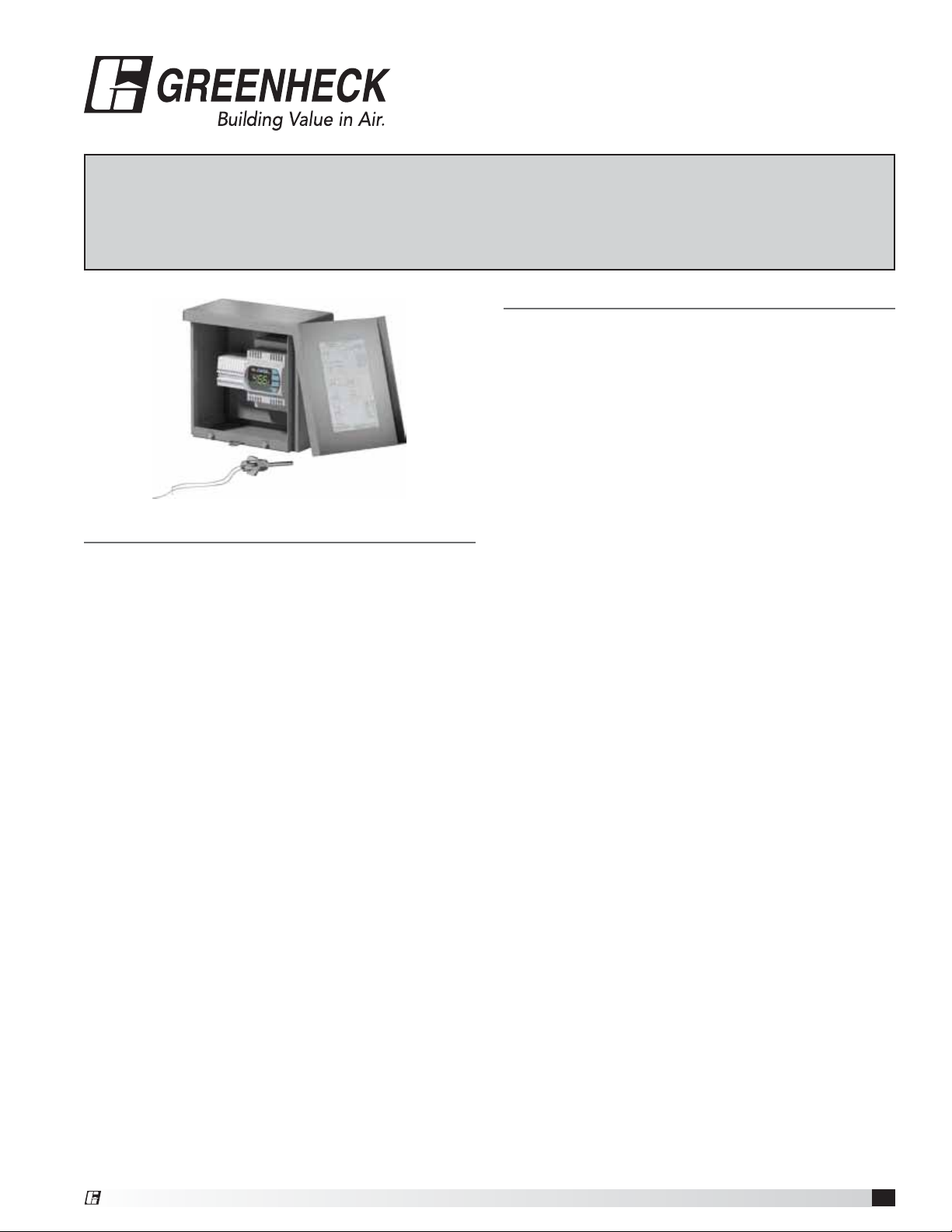
General Description
Description
The temperature interlock is designed to automatically
start kitchen hood exhaust fans and keep them
running while heat is being generated from the cooking
appliances. Hood systems should always be manually
started before equipment is turned on. If the fans are
forgotten to be turned on, the interlock will turn the fans
on once heat is detected. The interlock consists of a
temperature controller, resistive temperature detector
(RTD), junction box, Evergreen Compression Seal
Product Specification
Digital Temperature Interlock
International Mechanical Code (IMC) 2006 section
507.2.1.1 Compliant Electrical Package
Provide Greenheck Fan Corporation temperature
interlock electrical package as shown on plans and in
accordance with the following specification:
The temperature interlock(s) consists of a temperature
controller, resistive temperature detector (RTD), junction
box, fire proof/leak proof threaded fitting (Evergreen
Quik-Seal® and/or Evergreen Compression Seal), and
shall be a self-contained unit or as part of another preengineered electrical control package.
The temperature interlock package shall close a
relay powering the fans when the sensor detects the
temperature set point. The interlock shall hold the
circuit closed upon fan switch being turned off until the
temperature sensor detects a temperature below the set
point plus hysteresis. Once the temperature is below the
set point plus hysteresis, the fans shall shut down.
The temperature interlock package shall be constructed
by Greenheck Fan Corporation in accordance with
International Mechanical Code. The manufacturer shall
provide, upon request, the necessary data that confirms
compliance with the code listed above.
Due to continuous research, Greenheck Fan
Corporation reserves the right to change specifications
without notice.
threaded fitting, and is contained in a stand alone box or
can be added to a pre-engineered fan control center.
Purpose
To meet IMC 2006 section 507.2.1.1, interlock between
exhaust fans and cooking equipment. This system will
utilize a temperature sensor in the exhaust duct collar
or in capture area of hood to detect heat generated
from cooking operations and automatically activate the
exhaust fans if not already turned on. Field wiring may
be required depending on location of components.
Product Application
The temperature interlock is designed to be used
with Type I and Type II hoods. It is not to be used in
conjunction with exhaust fire dampers. Greenheck
recommends using one interlock per hood system
(activates all fans linked to system simultaneously).
Performance Goals
Automatically energize the exhaust fans when cooking
equipment generates heat. Basic controls will be
provided with a temperature sensor and will consist
of an 8x8 electrical box with controls and a labeled
terminal strip to hook-up incoming power and fan
starters. A temperature controller is used to keep the
exhaust fans running when the temperature controller
initially closes to prevent the fan from cycling on and
off at startup and shut down. Fans will shut down
automatically once the temperature has gone below the
set point plus hysteresis. The hysteresis can be adjusted
based on jobsite requirements.
®
Digital Temperature Interlock
1
Page 2
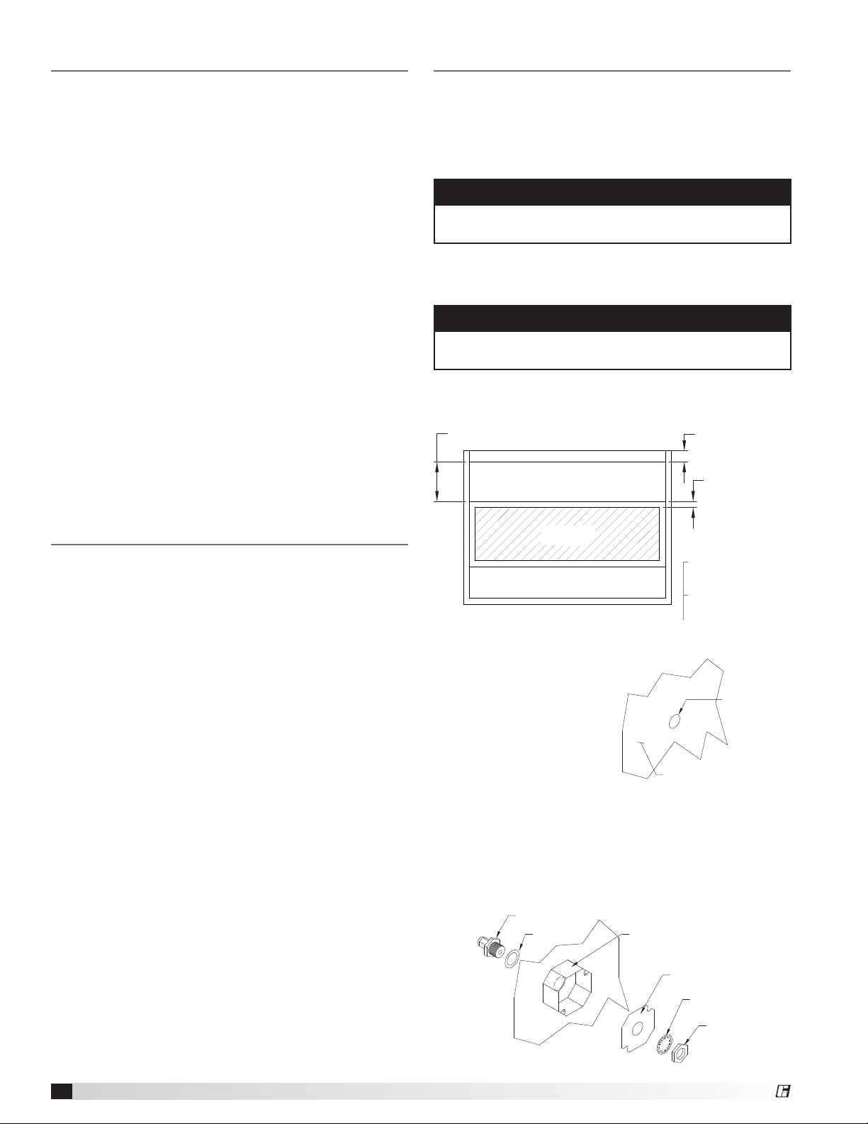
Table of Contents
0.75 to 0.875 inch
(19.0 to 22.2 mm)
diameter hole
Hood Surface
3 inch air space
19.525 inches
Sensor Install
(cutout area)
Exhaust Area
Supply Area
(optional)
P.O.BOX 410 SCHOFIELD, WI
TITLE
INSTR, ADJ. T
Installation
Product Specification ........................1
General Description ..........................1
Receiving and Handling .......................2
Installation
Hood Mounting .........................2-3
Duct Collar Mounting ......................3
Electrical Connections
Sensor Connections .......................3
Switch Connections to Control Box
or Fan Control Center ....................3
Circuit Connections .......................3
Calibration ...............................4
Factory Selected Parameters
Setting Parameters ....................3-4
Control Circuit Diagrams ....................5-6
Testing ...................................7
Operation ..................................7
Troubleshooting .............................7
Maintenance ...............................7
Frequently Asked Questions ...................8
Replacement Parts ..........................8
Codes and Standards Compliance ..............8
Our Commitment ............................8
Control Box Mounting
Locate an area with enough space to mount the control
box and fasten to the wall. Avoid installing the control
box in environments with high magnetic and/or radio
frequency interference.
NOTE
Control box may be factory mounted. If so, continue
to the next section.
Resistive Temperature Detector(s)
Hood Mounting
NOTE
Resistive temperature detector(s) may be factory
installed. If so, continue to the next section.
1. Locate flat area(s) at the top interior of the hood in
front of the filters, towards the front of the hood.
2 inch typical
Receiving and Handling
Upon receiving the equipment, check for both obvious
and hidden damage. Check to be sure that all parts of
the shipment, including accessories, are accounted for.
Make sure the equipment does not suffer any heavy
vibrations or knocks.
Storage
If a temperature interlock must be stored prior to
installation, it must be protected from dirt and moisture.
Indoor storage is recommended. For outdoor storage,
cover the control package with a tarp to keep it clean,
dry, and protected from UV (ultraviolet) radiation
damage.
Improper storage which results in damage to the unit
will void the warranty.
Top View of Exhaust Hood
2. Cut a 3/4 to 7/8-inch diameter
hole in the flat spot of the
capture tank. Make
sure the resistive
temperature detector(s)
will not interfere with fire
system nozzles and is
not within 12inches of
light fixtures.
3. Place the J-box plate inside of the octagon extension
ring and place over the hole.
4. Disassemble the compression seal and place
through hole and J-box plate as shown. Tighten the
nut inside the octagon extension ring.
Compression Seal
PN 463570
Gasket
Octagon Extension
PN 830125
Digital Temperature Interlock
2
J-Box Plate
PN 732396
Lock Washer
Nut
®
Page 3
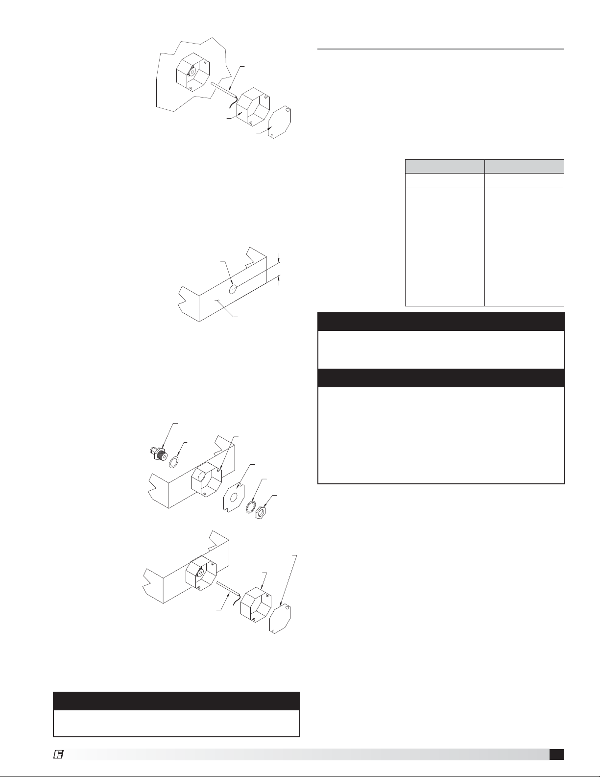
5. Place the resistive
temperature
detector through
the compression
Resistive Temperature
Detector (RTD)
PN 384925
seal and tighten
the compression
fitting.
6. Refer to Electrical
Connections
Octagon Extension
PN 830125
Octagon Cover
PN 380926
section for
instructions on wiring the temperature sensor.
7. Install the cover for the octagon box.
Resistive Temperature Detector(s)
Duct Collar Mounting
1. Locate the exhaust duct on top of the hood. A 3/4 to
7/8-inch (19.0 to 22.2 mm) diameter hole must be cut
into the duct 2inches
(50.8 mm) above the
hood top. Center the
hole along the side
of the duct. Make
sure that the resistive
temperature detector
will not interfere with
any fire system nozzles, or other items installed in
the exhaust duct. If an exhaust fire damper is present
the hood exhaust collar, it must be removed prior to
temperature sensor installation.
2. Place the J-box plate inside of the octagon extension
ring and place over the hole in the exhaust collar.
3. Disassemble the
compression
seal and place
through hole in
duct collar and
J-box plate as
shown. Tighten
the nut inside
the octagon
extension ring.
4. Place the
resistive
temperature
detector
through the
compression
seal and
tighten the
compression
fitting.
5. Refer to Electrical Connections section for
instructions on wiring the temperature sensor.
6. Install the cover for the octagon box.
All field installation and wiring of electrical equipment
must be done to meet NEC and local codes.
0.75 to 0.875 inch
(19.0 to 22.2 mm)
diameter hole
1/4-inch Compression Seal
PN 463570
Quik Seal
Gasket
Resistive Thermostat
Detector (RTD)
PN 384925
NOTE
Hood Exhaust Collar
Front Side
Octagon Extension
PN 830125
J-Box Plate
PN 732396
Lock Washer
Octagon Cover
PN 380926
Octagon Extension
PN 830125
2 inches
(50.8 mm)
Nut
Electrical Connections
Sensor Connections
1. Run two 18 awg stranded thermostat wires from
each temperature sensor to the appropriate electrical
circuit connections. (See Step 3 for connection
options).
2. In junction box, connect leads on RTD to the 18awg
conductors using appropriate size wire nuts.
• Wires are interchangeable with one another.
3. Choose
the final
connection
option
based on:
Do not connect temperature sensor in series with fan
power. This will result in damage to the temperature
sensor and will require replacement.
Separate as much as possible the probe and digital
input cables from inductive loads and power cables,
to avoid any electromagnetic disturbance. Never lay
power and probe cables in the same cable conduits
(including those for the electrical panel). Loosen
every screw and insert the cable end, next tighten
the screws and gently pull the cables to check their
tightness.
Switch Connections to Control Box or
Fan Control Center
Connect a Single Pole Single Throw (SPST) switch
to terminals S1H and S1. This is the same whether
temperature interlock is in a separate control box or
integrated in a kitchen fan control center.
Circuit Connections
1. Standard Interlock Control
• 120VAC, 10 or 15 amp circuit to terminals
H1 and N1
• 120VAC, 24VAC or other control circuit for fan
starter activation (factory separated from main
power connection shown in previous bullet)
- Control circuit power to terminal CP1
- Terminal CP2 to fan starter coils (hot)
2. Kitchen Fan Control Center Integration (KFCC)
• 120VAC, 15 amp circuit to H1 and N1 in fan
control center
- No additional control circuits are required
- Fan starters are factory-wired.
Sensor Terminals
First Sensor T1-A and T1-B
Others
(if applicable)
T2-A and T2-B
T3-A and T3-B
T4-A and T4-B
T5-A and T5-B
T6-A and T6-B
T7-A and T7-B
T8-A and T8-B
T9-A and T9-B
T10-A and T10-B
T11-A and T11-B
T12-A and T12-B
CAUTION
NOTE
®
Digital Temperature Interlock
3
Page 4

Calibration
The temperature controller is preset by the factory to
turn the fans on at 95°F. This is controlled by the set
point on the temperature controller. The temperature set
point may have to be adjusted slightly depending on
both ambient and cooking conditions. The adjustment is
made through the buttons on the temperature controller.
The controller is capable of monitoring two separate
sensors. If more than one sensor is utilized with a single
controller, two set points can be adjusted. To adjust,
follow these instructions:
1. If setting set point 1 (St1), press Set. The display
shows St1 and then the current value of St1.
If setting set point 2 (St2), press Set twice, slowly.
The display shows St2 and then the current value of
St2.
2. Press the S or T to change the set point.
3. Press Set to confirm the new value of either St1 or
St2.
4. Check system operation before making additional
adjustments.
Factory Selected Parameters
The factory will pre-program the controllers to be
properly integrated into the control panel. Except for
the set points, the other parameters should never need
adjusting. However, there are three different types of
parameters that are accessible on the controller. Access
differs depending on the type: set point; frequently used
parameters (P); and configuration parameters (c, d, F).
NOTE
The controller is pre-programed at the factory to
operate with the digital temperature interlock
components. No further parameter changes should
be necessary.
Setting type P parameters
Type P parameters (frequents) are indicated by a code
beginning with the letter P, followed by one or two
numbers.
Prg
1. Hold the
shows the firmware revision code (e.g. r2.1) is
shown, after 5 seconds (in the event of alarms, first
the buzzer is muted) the code of the first type P
modifiable parameter, P1.
2. Press S or T until reaching the desired parameter.
3. Press Set to display the associated value.
4. Increase or decrease the value using S or T
respectively, until reaching the desired value.
5. Press Set to temporarily save the new value and
return to the display of the parameter code.
6. Repeat operations from 4 to 5 to set other
parameters.
7. To permanently save the new values of the
parameters, press
the parameter setting procedure.
button, after 3 seconds the displays
mute
Prg
for 5 seconds, thus exiting
mute
Setting type c, d, F parameters
Type c, d or F (configuration) parameters are indicated
by a code beginning with letters c, d, F respectively,
followed by one or two numbers.
1. Press
seconds. The display shows the number 0.
Prg
and Set together for more than 5
mute
2. Press S or T until displaying the password: 77
3. Confirm by pressing Set
4. If the value entered is correct, the first modifiable
parameter c0 will be shown, otherwise the standard
display will resume.
5. Press S or T until reaching the parameter to be
modified.
6. Press Set to display the associated value.
7. Increase or decrease the value using S or T
respectively, until reaching the desired value.
8. Press Set to temporarily save the new value and
return to the display of the parameter code.
9. Repeat operations from 5 to 8 to set other
parameters.
10. To permanently save the new values of the
parameters, press
the parameter setting procedure.
Prg
for 5 seconds, thus exiting
mute
Factory Selected Parameters
Parameter Description Factory Setting
St1 Set Point 1 95
St2 Set Point 2 95
c0 Operating Mode 1
P1 Set Point Differential 5.0
P2 Set Point Differential 5.0
P3 Dead Zone Differential 0
c6 Delay between two outputs 0
c9 Minimum relay on time 5
c10 Probe alarm output status 1 1
d10 Probe alarm output status 2 1
c11 Output Rotation 4
c13 Probe Type 3
P14 Probe 1 Calibration 0
P15 Probe 2 Calibration 0
c18 Unit of Measure 1
c19* Function of probe 2 0 or 7
*Parameter c19 is factory set at 0. If controller is connected to two
sensors, then the parameter is factory set at 7..
Displaying the Inputs
1. Press T. The current input will be displayed,
alternating with the value:
b1 : probe1
b2 : probe 2
di1 : digital input 1
di2 : digital input 2
St1 : set point 1
St2 : set point 2
2. Press S or T to select the input to be displayed.
3. Press Set for three seconds to confirm.
Digital Temperature Interlock
4
®
Page 5

Control Circuit Diagram (Standard Control)
This is an example of a generic wiring diagram for standard control. This diagram has 12 sensors
which provide temperature interlock function for two exhaust fans and one supply fan.
(All starters provided by others, external to this control box).
Wiring for additional sensors (optional)
This Control Panel only provides control power to
signal operation of supply and exhaust starters.
Starters are NOT provided by manufacturer.
Starters to be provided by, wired and mounted by others.
®
Digital Temperature Interlock
5
Page 6

Control Circuit Diagram (Fan Control Center)
This is an example of a generic wiring diagram for temperature interlock integration into a KFCC.
This diagram has 2 sensors that provide temperature interlock function for one exhaust fan and one supply fan.
To see your job specific drawing, look on the inside panel of the KFCC cabinet.
12 inches
LIGHTS
FANS
18 inches
6 inches
Digital Temperature Interlock
6
®
Page 7

Testing
Troubleshooting
1. Turn fan switch on, then off to ensure proper fan
operation before cooking equipment is started. Once
this is verified, testing can proceed.
2. Heat up cooking equipment with fans off. Once the
temperature reaches the set point of the temperature
controller the fans will start within 5minutes. If the
fans take more than 5 minutes to start, decrease the
temperature set point by adjusting the set point on
the temperature controller (see Calibration).
3. If an adjustment was made in Step 2, repeat now.
4. After verification of fan start-up, shut down cooking
equipment. The fan switch should still be in the off
position. Once cooking equipment has cooled below
the set point plus hysteresis, the fans will shut down.
CAUTION
The probes should never be exposed to direct flame.
The probes are rated up to 250°F.
CAUTION
EXPOSING THE SENSOR TO DIRECT FLAME MAY
RENDER THE SENSOR INOPERABLE AND WILL
VOID THE WARRANTY.
NOTE
During testing, if fans do not start automatically in
the first 10 minutes of cooking equipment activation,
manually start fans to avoid accidental fire system
dump due to heat build-up.
1. Controller(s) display E01 or E02 and fans will
not shut off.
• E01 and E02 represent probe faults
• Check probe resistance between the two leads
when disconnected from the system. At room
temperature (77°F), the probe will read 1025 ohms
• Check wiring connections between the sensor
and control cabinet
2. Fans do not turn on automatically upon
cooking equipment activation.
• Check wiring to control panel or relay box
• Multiple sensors must be wired separately
• Temperature set point too high, decrease set point
• No power to fans, check breakers/starters/relays
3. Fans do not shut off.
• Check the controller to determine if there is a
probe error of E01 or E02. If yes, refer to the
controller display error message, item 1 above.
• Switch must be in the off position
• Cooking equipment hot, wait for it to cool
• Temperature set point too low, increase set point
• Ensure wires are connected to appropriate control
circuit
4. Fans do not turn on quick enough.
• Decrease temperature set point
Maintenance
Operation
1. Turn fans on and off using the fan switch. It is normal
for the fans to remain running after the switch is
turned off. The exhaust temperature controller will
open after heat is no longer present under the hood
and the temperature is below the set point plus
hysteresis, the fans shall shut down.
2. In the event that the cooking equipment is started
without turning the fans on manually, the fans will
turn on automatically and remain running with
the presence of heat under the hood. Once the
temperature is below the set point plus hysteresis,
the fans shall shut down.
Daily
Clean the temperature sensor with cloth and degreaser.
Keep clean for best performance.
Weekly
Dependant on grease production and grease filter type,
clean temperature sensor.
Seasonal
May have to change temperature setting on the
temperature controller if ambient kitchen temperatures
fluctuate between summer and winter seasons.
Whom to call
Contact your local Greenheck representative.
What to have ready for the call
Sales order, serial number and description of product.
Sales Order Number ________________________
Serial Number ______________________________
®
Digital Temperature Interlock
7
Page 8

Frequently Asked Questions
Replacement Parts
What temperature is the temperature controller set
to from the factory?
95º Fahrenheit.
Will the temperature interlock automatically start/
stop the fans?
When connected properly to fan starters the
temperature interlock will automatically control
the fans without input from the user. However, the
intended use of the temperature interlock is as backup to manual control.
May I connect the power going to my fan directly
through the control box?
No, the control box should only use control voltage
only (24-120V), and a separate 120V power source
is required to run the temperature interlock controls.
Greenheck recommends the use of starters sized for
each fan.
Can I use one control box for multiple hood systems?
This can be done, however, it is not recommended.
Any one of the temperature controllers would turn on
all hoods running on that control box. It is better to
have one hood/fan per control box, plus a significant
energy savings can be obtained if one or more of the
hoods is not in operation.
Can I still turn my fan on and off?
Yes, the temperature interlock is designed to be
operated with a typical on/off switch. The fan may not
turn off directly after turning the fan switch off, it will
sense when the cooking operations have cooled and
then turn off.
Part
Number
384925
384920
830125
732396 J-Box Plate
380926
384905
384908
463570
Temperature Sensor (RTD)
MAMAC TE-700-0-3-A
Temperature Controller
CAREL iR33-DN33 DN33W7HR20
Extension, Octagon (drilled)
SC55151-1/2 (380928)
Cover, Octagon Box
SC#54-C-1RACO 722
Terminal Block, Single Pole,
DIN-RAIL MT, ABB ZS6
Jumper, DIN-RAIL
Terminal Block Two Pole ABB JB6-2
Evergreen Compression Seal
1/4-inch, #302
Description
Codes and Standards Compliance
• UL 710
• National Fire Protection Association (NFPA 96)
• International Mechanical Code (IMC) 2006
Section 507.2.1.1
Our Commitment
As a result of our commitment to continuous improvement, Greenheck reserves the right to change specifications
without notice.
Specific Greenheck product warranties are located on greenheck.com within the product area tabs and in the
Library under Warranties.
AMCA Publication 410-96, Safety Practices for Users and Installers of Industrial and Commercial Fans, provides additional safety
information. This publication can be obtained from AMCA International, Inc. at www.amca.org.
®
Phone: (715) 359-6171 • Fax: (715) 355-2399 • E-mail: gfcinfo@greenheck.com • Website: www.greenheck.com
474750 • Digital Temperature Interlock, Rev. 3, November 2012 Copyright 2012 © Greenheck Fan Corporation
8
 Loading...