

Page 1
Part #471738
®
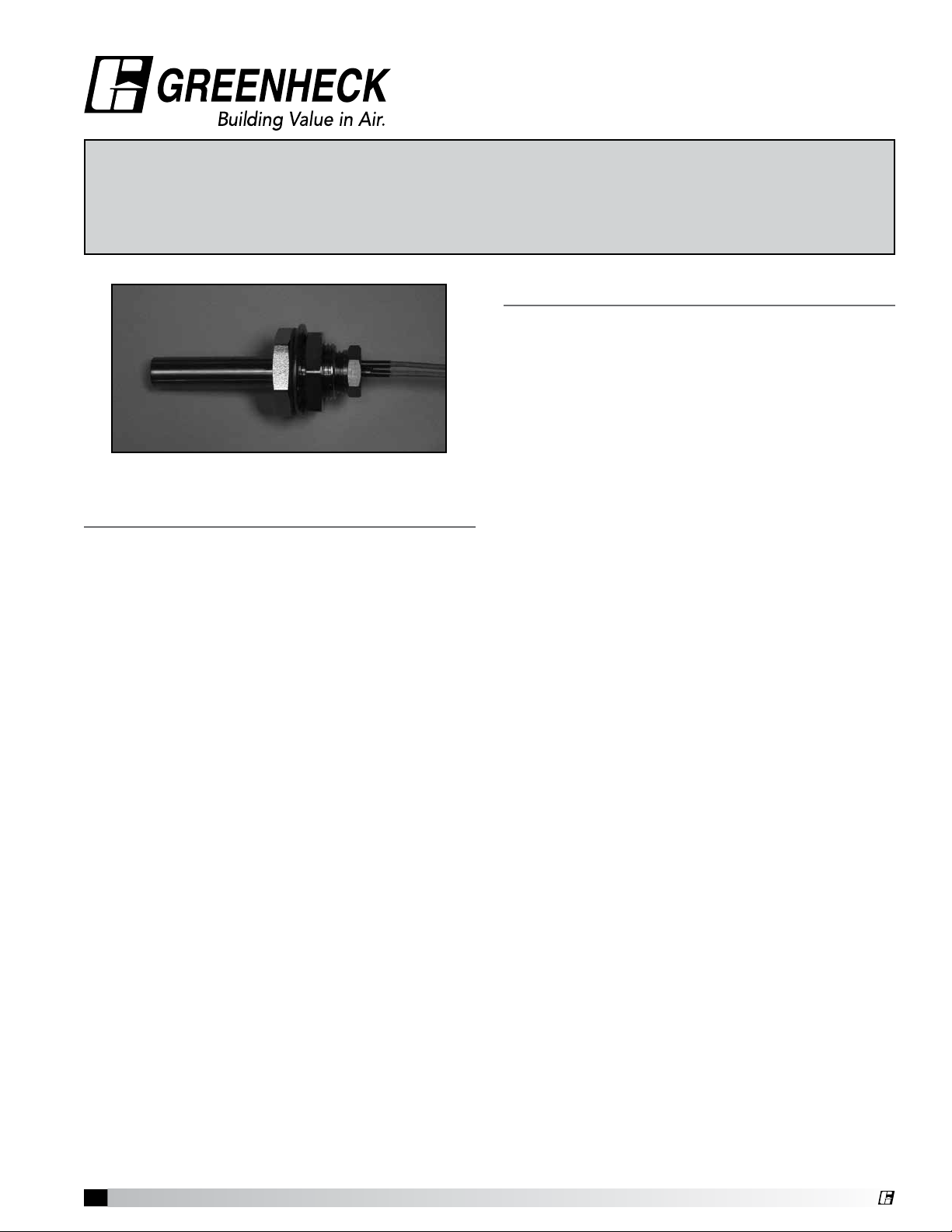
Temperature Interlock
Installation, Operation and Maintenance Manual
Please read and save these instructions. Read carefully before attempting to assemble, install, operate or maintain the
product described. Protect yourself and others by observing all safety information. Failure to comply with instructions
could result in personal injury and/or property damage! Retain instructions for future reference.
General Description
Description
The temperature interlock is designed to automatically
start kitchen hood exhaust fans and keep them
running while heat is being generated from the
cooking appliances. Hood systems should always be
manually started before equipment is turned on. If the
fans are forgotten to be turned on, the interlock will
turn the fans on once heat is detected. The interlock
consists of an adjustable thermostat, junction box,
Evergreen Quik-Seal threaded fitting, and is contained
Product Specification
Temperature Interlock
International Mechanical Code (IMC) 2006 section
507.2.1.1 Compliant Electrical Package
Provide Greenheck temperature interlock electrical
package as shown on plans and in accordance with
the following specification:
The temperature interlock(s) consists of an adjustable
thermostat, junction box, fire proof/leak proof
threaded fitting (Evergreen Quik-Seal® and/or
Evergreen Compression Seal), and shall be a selfcontained unit or as part of another pre-engineered
electrical control package.
The temperature interlock package shall close a
relay powering the fans when the set temperature is
reached at the thermostat. The interlock shall hold the
circuit closed upon fan switch being turned off until
the temperature at the sensor decreases below the
set point at which point the timed relay will begin a
countdown. Once the countdown has expired and as
long as the temperature has remained below the set
point, the fans shall shut down.
The temperature interlock package shall be
constructed by Greenheck in accordance with
International Mechanical Code. The manufacturer
shall provide, upon request, the necessary data that
confirms compliance with the code listed above.
Due to continuous research, Greenheck reserves the
right to change specifications without notice.
in a stand alone box or can be added to a preengineered fan control center.
Purpose
To meet IMC 2006 section 507.2.1.1, interlock
between exhaust fans and cooking equipment. This
system will utilize a temperature sensor in the exhaust
duct collar or in capture area of hood to detect heat
generated from cooking operations and automatically
activate the exhaust fans if not already turned on.
Field wiring may be required depending on location of
components.
Product Application
The temperature interlock is designed to be used
with Type I and Type II Hoods. It is not to be used in
conjunction with exhaust fire dampers. Greenheck
recommends using one interlock per hood system
(activates all fans linked to system simultaneously).
Performance Goals
Automatically energize the exhaust fans when cooking
equipment generates heat. Basic controls will be
provided with a thermostat and will consist of an 8x8
electrical box with controls and a labeled terminal
strip to hook-up incoming power and fan starters.
An adjustable delay is used to keep the exhaust fans
running when the thermostat initially closes to prevent
the fan from cycling on and off at startup and shut
down. Fans will shut down automatically 20 minutes
after the thermostat opens its contact. The time delay
can be adjusted from 1-100 minutes based on jobsite
requirements.
Temperature Interlock
1
®
Page 2

Table of Contents
Product Specification . . . . . . . . . . . . . . . . . . . . . . . . 1
General Description . . . . . . . . . . . . . . . . . . . . . . . . . 1
Receiving and Handling . . . . . . . . . . . . . . . . . . . . . . 2
Installation
Hood Mounting . . . . . . . . . . . . . . . . . . . . . . . . . . 3
Duct Collar Mounting . . . . . . . . . . . . . . . . . . . . . . 3
Electrical Connections
Thermostat Connections . . . . . . . . . . . . . . . . . . . 4
Breaker Panel to Control Box or
Fan Control Center . . . . . . . . . . . . . . . . . . . . . . 4
Circuit Connections . . . . . . . . . . . . . . . . . . . . . . . 4
Calibration . . . . . . . . . . . . . . . . . . . . . . . . . . . . . . . . . 4
Control Circuit Diagrams . . . . . . . . . . . . . . . . . . . 5-6
Testing . . . . . . . . . . . . . . . . . . . . . . . . . . . . . . . . . . . 7
Operation . . . . . . . . . . . . . . . . . . . . . . . . . . . . . . . . . 7
Troubleshooting . . . . . . . . . . . . . . . . . . . . . . . . . . . . 7
Maintenance . . . . . . . . . . . . . . . . . . . . . . . . . . . . . . . 7
Frequently Asked Questions . . . . . . . . . . . . . . . . . . 8
Replacement Parts . . . . . . . . . . . . . . . . . . . . . . . . . . 8
Codes and Standards Compliance . . . . . . . . . . . . . 8
Warranty . . . . . . . . . . . . . . . . . . . . . . . . . . . . . . . . . . 8
Receiving and Handling
Upon receiving the equipment, check for both obvious
and hidden damage. If damage is found, record all
necessary information on the bill of lading and file
a claim with the final carrier. Check to be sure that
all parts of the shipment, including accessories, are
accounted for.
Storage
If a temperature interlock must be stored prior
to installation it must be protected from dirt and
moisture. Indoor storage is recommended. For
outdoor storage, cover the hood with a tarp to keep it
clean, dry, and protected from UV (ultraviolet) radiation
damage.
Improper storage which results in damage to the unit
will void the warranty.
Temperature Interlock
2
®
Page 3
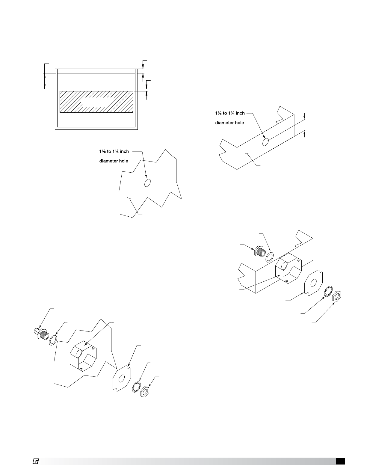
Installation – Hood Mounting
Gasket
Compression Seal
PN 452614
Nut
Lock Washer
Octagon Extension
PN 830125
Junction Box Plate
PN 732396
19.525 inches
3 inch air space
2 inch typical
Exhaust Area
Supply Area
(optional)
Sensor Install
(cut out area)
Gasket
Compression Seal
PN 452614
Nut
Lock Washer
Octagon Extension
PN 830125
Junction Box Plate
PN 732396
Gasket
1/2 inch Quik-Seal
PN 451168
Recommended thermostat mounting location is in
the flat interior of the hood and at least 8 inches
(20.32cm) from light fixture.
Duct Collar Mounting
1. Locate the exhaust duct on top of the hood. A
11⁄8to 1¼-inch (28.58 to 31.75 mm) diameter hole
must be cut into the duct 2inches (50.8 mm)
above the hood top. Center the hole along the
side of the duct. Make sure that the thermostat
will not interfere with any fire system nozzles, or
other items installed in the exhaust duct. If an
exhaust fire damper is present the hood exhaust
collar, it must be removed prior to thermostat
installation.
Hood Plan View
1. Locate the flat
area(s) at the
(28.58 to 31.75 mm)
top interior of
the hood in front
of the filters,
towards the front
of the hood. A
11⁄8 to 1¼ inch
(28.58 to 31.75
mm) diameter
Hood Surface
hole must be cut
into the top of the capture tank. Make sure the
thermostat will not interfere with the fire system
nozzles and is not within 8 inches (20.32cm) of
the light fixtures.
2. Insert the Evergreen Compression Seal fitting into
the hole from the inside of the hood, making sure
the gasket is placed on the fitting before inserting
it into the hole. Install the lock washer and 11⁄2inch
(38mm) nut on the threaded portion of the
compression seal fitting and tighten securely.
Compression Seal
PN 452614
Gasket
Octagon Extension
PN 830125
(28.58 to 31.75 mm)
Hood Exhaust Collar
(front side)
2. Insert the Evergreen Quik-Seal fitting into the
hole from the inside of the duct, making sure the
gasket is placed on the fitting before inserting it
into the hole. Install the lock washer and 1
(38.1mm) nut on the threaded portion of the
Evergreen Quik-Seal fitting and tighten securely.
Gasket
1/2 inch Quik-Seal
Octagon Extension
PN 451168
PN 830125
Junction Box Plate
PN 732396
Lock Washer
Exploded View (Components)
2 inches
(50.8 mm)
Nut
1
⁄2inch
3. Place the junction box provided over the fitting on
4. Thread the thermostat into the compression seal
Junction Box Plate
PN 732396
Lock Washer
Nut
Exploded View (Components)
top of the hood, keeping the fitting centered in the
box.
fitting and tighten to 35 ft-lbs. (4.84 m-kgs).
®
3. Place the junction box provided over the fitting
and tack weld the junction box to the exhaust duct
keeping the fitting centered in the box. (Welding
optional).
4. Thread thermostat into Evergreen Quik-Seal fitting
and tighten to 35 ft-lbs (4.84 m-kgs).
Temperature Interlock
3
Page 4

Electrical Connections
Thermostat Connections
1. Run two 14 awg, 90° minimum conductors, black,
in conduit from each thermostat to the appropriate
electrical circuit connections. (See Step 3 for
connection options).
2. In junction box, connect leads on thermostat to
the 14 awg conductors using appropriate size
wire nuts.
• Wires are interchangeable with one another.
• Wire thermostats in parallel if there are multiple
exhaust ducts.
3. Choose the final connection based on:
• Terminals T1 & T2 in fan control center (KFCC).
• Terminals 5 & 6 in control box on top of hood/
utility cabinet.
CAUTION
Do not connect thermostat in series with fan power.
On/off cycling of the fans will result during startup and shutdown periods. Use the thermostat for
control wiring only.
Calibration
Thermostat is preset by factory to 95°F and has a
slow make and break contact. It will make contact on
a temperature rise and break contact on temperature
fall. The temperature set point may have to be
adjusted slightly depending of both ambient and
cooking conditions. The adjustment knob is located
on the back of the thermostat. Use a small blade
screwdriver to make the adjustments.
1. Turn counterclockwise to increase the temperature
set point, turn clockwise to decrease the
temperature set point.
2. Quarter revolution in either direction corresponds
to a 22.5°F adjustment. Be sure to make small
adjustments, about 1/16 of a turn (≈6°F) or less at
one time.
3. Do not exceed more than one-half revolution in
either direction.
4. Check system operation before making additional
adjustments.
Breaker Panel to Control Box or Fan Control
Center
1. Connect a Single Pole Single Throw (SPST) switch
to one of the following based on application:
• Terminals 3 & 4 in the control box.
• Terminals S1 & S1H in the fan control center.
Circuit Connections
1. Standard Interlock Control
• 120V, 10 or 15 amp circuit to terminals 1 & 2
• Control voltage for fan starter activation
• 120V, 24V or other control circuit
(drawing on page 8)
• Control circuit power to terminal 7
• Terminal 8 to fan starter coils
• 120V only control circuit
(drawing on page 9)
• Terminals 7 & 8 to fan starter coils
2. Fan Control Center Integration (KFCC)
• Power to H1 & N1 in fan control center
• No additional control circuits are required fan
starters are factory wired
Temperature Interlock
4
®
Page 5

BK
YW
YW
WT
OR OR
RD
RD
CONTROL INPUT: 120VAC, 10AMPS FROM BREAKER
CONTROL VOLTAGE FROM BREAKER
OPTIONAL EXHAUST ON IN FIRE
FAN STARTERS
L1
N
G
Painted Only
NEMA 3R
L1
N
G
2
TS1
TS2
5
6
1
7 3 4 8
S1
C
1
6
2
NO
NO NC
ST
ST
ST
COM
EXHAUST
FS
FIRE SYSTEM
MICROSWITCH
383271 (OFF DELAY 1-100 MINUTES)
THERMOSTAT(S)
EXHAUST
SUPPLY
GREENHECK
Control Circuit Diagram (Standard Control)
TS1
TS2
COM
THERMOSTAT(S)
FAN STARTERS
ST
EXHAUST
ST
EXHAUST
ST
SUPPLY
L1
YW
1
BK
RD
7 3 4 8
OPTIONAL EXHAUST ON IN FIRE
CONTROL INPUT: 120VAC, 10AMPS FROM BREAKER
5
YW
6
1
C
OR OR
S1
6
383271 (OFF DELAY 1-100 MINUTES)
2
NO
FS
FIRE SYSTEM
MICROSWITCH
NO NC
RD
WT
8.0
G
N
GREENHECK
2
Painted Only
NEMA 3R
8.0
4.0
L1
CONTROL VOLTAGE FROM BREAKER
Thermostat factory set at 95ºF (35ºC)
Do not turn adjustment screw more than
1/2 revolution in either direction.
1/8 turn equals 12ºF (6.7ºC)
Counterclockwise = increase temperature setting
Clockwise = decrease temperature setting
G
N
ADJUSMENT
SCREW
THERMOSTAT
CONNECTIONS
Circuit
Control
Fan Switch
Connection
Thermostat
Connection
Fan Starter
Control Circuit
FIELD
Torque to 18 in-lbs.
120/1 - 10 A
NEUTRAL
S1
H
MUA EX EX
N
T2T1
1
2
3
4
5
6
7
8
®
Temperature Interlock
Part #471503
5
Page 6

closed w/power at H1/N1 & fire system armed
Control Circuit Diagram (Fan Control Center)
L1
CONTROL INPUT: 120VAC, 15AMPS FROM BREAKER
H1
TYP. 1 SENSOR PER
TS1
EXHAUST COLLAR
TS2
WIRED IN PARALLEL
FACTORY MOUNTED SWITCH
LT1
S1N
R
ST1
A1ORA2
OL1
96
RD
T1
S1H
6
T2
R8
1
2
(Off Delay 1-100 minutes)
NOC
S1
S1
FACTORY WIRING TO SWITCH
OR
N
G
N1
WH
WH
95
INPUT POWER
3 WIRE
208/3 PHASE
FROM BREAKER
INPUT POWER
3 WIRE
208/3 PHASE
FROM BREAKER
12.0
LIGHTS
FANS
18.0
6.0
L1
L2
L3
L1
L2
L3
CONTROL PANEL
Installation Location:
Ship Loose
"LIGHTS" SWITCH
"FAN" SWITCH
OL1 ST1
T1
T1
L1
L2
L3
L1
L2
L3
T2
T2
T3
T3
OL2 ST2
T1
T1
T2
T2
T3
T3
Exh
FAN 1
Supply
FAN 2
Panel Mark:
Hood Mark(s):
F1-E EF-1 1.5 208 3 5.7 14 ga 15 amp
F2-S SF-1 1 208 3 4.6 14 ga 15 amp
Qty. Fan Switches (0-3)
1
Qty. Light Switches (0-3)
1
Qty. Temp. Switches (0-1)
0
One Switch for L & F
Temperature Interlock
X
Mounted Sensors - Factory
0
Mounted Sensors - Field
1
Heat Switch
Cool Switch
G
AD Switch
Remote Switches
Audible Alarm
Gas Reset
Power for Gas Solenoid
Power for Shunt Trip
G
Spare Fire Switch Contact
(dry contacts for building alarm)
Spare Relay Contacts
(can be used for shunt trip, alarms, etc.)
A
B
open w/power at H1/N1 & fire system armed
A
closed on fire or no power
B
open on fire or no power
RD
OR
R1
R1
YW
1
3
4
1
ST2
A1YWA2
OL2
96
WH
95
Fan MarkMotor HP
RD/RD
C2
BR/BK
NC2
BK/YW
NO2
RD
C3
BR
NO3
BK
NC3
Mark 1
Volt
Tempering SW
Gas Off w/Fans
NC
C
NO
4
R2
1
3
WirePH FLA Breaker
Exhaust in Fire
X
MUA Interface
Lights Out in Fire
Fire Relay (#1)
X
Extra Fire Relay (#2)
Extra Fire Relay (#3)
DPDT Relay w/SF
DPDT Relay w/EF
Off Delay Relay
SF Failure Light
EF Failure Light
Fan Failure Light (Appl.)
Damper
Aux. Supply Contact
Tie in WWCP
Ansul / Amerex
RD/RD
BR/BK
FS2
BK/YW
(activated by FS1)
RD
C4
BR
NO4
A
B
NC4
5
BK
6
R2
8
RD
C1
THERMOSTAT
RD(RD)
ADJUSTMENT
SCREW
FS1
BR(BK)
NC
C
BK(YW)
NO
NC1
NO1
BR
R1
2
7
THERMOSTAT CALIBRATION
FACTORY SETTING AT 95°F (35°C)
DO NOT TURN ADJUSTMENT SCREW MORE THAN
1/2 REVOLUTION IN EITHER DIRECTION
1/8 TURN = 12°F (6.7°C)
INCREASE TEMPERATURE = COUNTERCLOCKWISE
DECREASE TEMPERATURE = CLOCKWISE
Switches Mounting - On Control Package
L1
BK
H2
WH
R2
7
2
LIGHT INPUT: 120VAC,
15AMPS FROM BREAKER
S-1
B2
LT
1400W max.
LT
W2
WH
N
N2
TORQUE:
TERMINAL STRIPS = 18 IN/LB.
GROUNDING BAR = 20 IN/LB.
LABEL DESCRIPTION
Exhaust Fan
EF
Supply Fan
SF
Starter
ST
OverLoad
OL
Contactor
C
Ground
G
Switch
S
Light
LT
Fire Switch
FS
Relay
R
Air Flow Switch
AF
Gas Solenoid
SV
STB
Shunt Trip Breaker
Damper
D
PushButton
PB
Evap Cooler
EC
NOTES:
Drawing shown de-energized at L1 (term. #H1),
w/ Fire System armed (non-fire mode).
(normal operation, R1 & R2 are energized) If wall
mounted prewire, or field installed fire system,
the fire system microswitches must be field wired.
UL LISTED
Wiring Diagram #
UNDER SUBJECT 891
FIELD WIRING:
USE MINIMUM
60° Copper Wire
FACTORY WIRING
FIELD WIRING
ALL WIRING 90°C 14 GA.
UNLESS SPECIFIED
WIRE COLOR
BK - black
BL - blue
BR - brown
OR - orange
PR - purple
RD - red
YW - yellow
WT - white
FILE #E200616
T110-2-311
Temperature Interlock
6
®
Page 7

Testing
Troubleshooting
1. Turn fan switch on, then off to ensure proper fan
operation before cooking equipment is started.
Once this is verified, testing can proceed.
2. For testing only, locate the time delay relay. Turn
the time adjustment knob counterclockwise to the
first mark in order to expedite the testing process.
Make a note as to where the timer was originally
set.
3. Heat up cooking equipment with fans off. Once
the duct temperature reaches the set point of the
thermostat the fans will start, preferably within
5minutes. If the fans take more than 5 minutes
to start, decrease the temperature set point by
turning the adjustment screw 1/16 turn clockwise.
Do not apply direct flame to the thermostat
4. If an adjustment was made in Step 3, repeat now.
5. After verification of fan start-up, shut down
cooking equipment. The fan switch should still be
in the off position. Once cooking equipment has
cooled, the thermostat will open triggering the
timer to begin. Once time has expired, the fans will
shut down. Thermostat operation can be verified
by checking voltage (120V) between T2 and
neutral on either the control box or KFCC. 120V
will be present when the thermostat senses heat.
6. Once proper operation has been verified, set
the dial on the timer relay to its original setting
(approximately 20 minute delay).
NOTE
During testing, if fans do not start automatically in
the first 10 minutes of cooking equipment activation,
manually start fans to avoid accidental fire system
dump due to heat build-up.
Fans do not turn on automatically upon cooking
equipment activation.
• Check wiring to control panel or relay box,
thermostats must be wired in parallel
• Temperature set point to high, decrease set point
• No power to fans, check breakers/starters/relays
Fans do not shut off.
• Switch must be in the off position
• Cooking equipment hot, wait for it to cool
• Temperature set point too low, increase set point
• Ensure wires connected to appropriate control
circuit
• Time delay too great, turn down timer
Fans cycle off to on when turned off.
• Cooking equipment not cooled enough, retry in
5minutes
Fans do not turn on quick enough.
• Decrease temperature set point
Maintenance
Daily
Clean thermostat with cloth and degreaser. Keep
clean for best performance. (Can clean weekly
depending upon grease accumulation).
Weekly
Dependant on grease production and grease filter
type, clean thermostat.
Seasonal
May have to change temperature setting on back of
thermostat if ambient kitchen temperatures fluctuate
between summer and winter seasons.
Operation
1. Turn fans on and off using the fan switch. It is
normal for the fans to remain running after the
switch is turned off. The exhaust duct thermostat
will open after heat is no longer present under
the hood which will activate the timer to begin
its countdown. Once time has expired, fans will
shut down. The timer is adjustable from 1-100
minutes. The recommended time delay setting is
approximately 20 minutes.
2. In the event that the cooking equipment is started
without turning the fans on manually, the fans
will turn on automatically and remain running
with the presence of heat under the hood. The
exhaust duct thermostat will open after heat is no
longer present under the hood which will activate
the timer to begin its countdown. Once time has
expired, fans will shut down.
®
Whom to call
Contact your local Greenheck representative.
What to have ready for the call
Sales order, serial number and description of product.
Sales Order Number _______________________
Serial Number _____________________________
Temperature Interlock
7
Page 8

Frequently Asked Questions
Replacement Parts
What temperature is the thermostat set from the
factory?
95º Fahrenheit.
Will the temperature interlock automatically start/
stop the fans?
When connected properly to fan starters the
temperature interlock will automatically control the
fans without input from the user. However intended,
use as a back-up to manual control.
May I connect the power going to my fan directly
through the control box?
No, the control box should only use control voltage
only (24-120V), and a separate 120V power source
is required to run the temperature interlock controls.
Greenheck recommends the use of starters sized for
each fan.
What is the purpose of the timer in the control box?
The timer is used to delay the shut down of the fans
to prevent fan on/off cycling while the temperature
in the exhaust duct can reach steady state. Without
the delay, cycling could occur both on startup
or shutdown of cooking equipment. The delay is
typically set at 20 minutes.
Can I use one control box for multiple hood systems?
This can be done, however, it is not recommended.
Any one of the thermostats would turn on all hoods
running on that control box. It is better to have one
hood/fan per control box, plus a significant energy
savings can be obtained if one or more of the hoods
is not in operation.
Can I still turn my fan on and off?
Yes, the temperature interlock is designed to be
operated with a typical on/off switch. The fan may
not turn off directly after turning the fan switch off, it
will sense when the cooking operations have cooled
and then turn off.
Quantity
1 383923
1 451168
1 830125
1 380926
1 381460
3 382859
2 382858
1 383271
1 452614
Part
Number
Description
Thermostat, Vulcan 1C2B9
5/8-inch Type C
Evergreen Quik-Seal, 1/2-inch
#171 (1-1/8 inch hole size)
Ext, Octagon (drilled)
SC55151-1/2 (380928)
Cover, Octagon Box
SC#54-C-1RACO 722
Encl, 8X8X4 NEMA3R
ELMATE RC-884-SC3R
Terminal Block, 3 pole,
DIN-RAIL MT, BUS NDN3-WH
Jumper, DIN-RAIL Terminal
Block #JNDN3
Timer SSAC #KRDB424 SPST
1-100 min.
Evergreen Compression Seal,
5/8-inch, #302
Codes and Standards Compliance
UL 710
•
• National Fire Protection Association (NFPA 96)
• International Mechanical Code (IMC) 2006
Section 507.2.1.1
Warranty
Greenheck warrants this equipment to be free from defects in material and workmanship for a period of one year from
the shipment date. Any units or parts which prove defective during the warranty period will be replaced at our option
when returned to our factory, transportation prepaid. Motors are warranted by the motor manufacturer for a period of
one year. Should motors furnished by Greenheck prove defective during this period, they should be returned to the
nearest authorized motor service station. Greenheck will not be responsible for any removal or installation costs.
As a result of our commitment to continuous improvement, Greenheck reserves the right to change specifications
without notice.
AMCA Publication 410-96, Safety Practices for Users and Installers of Industrial and Commercial Fans, provides additional
safety information. This publication can be obtained from AMCA International, Inc. at: www.amca.org.
®
Phone: (715) 359-6171 • Fax: (715) 355-2399 • E-mail: gfcinfo@greenheck.com • Web site: www.greenheck.com
471738 • Temperature Interlock, Rev. 1, April 2010 Copyright 2010 © Greenheck Fan Corporation
8
 Loading...