

Page 1
Technical Instructions
Document No. 152-013P25
April 28, 2003
Powers™ Controls
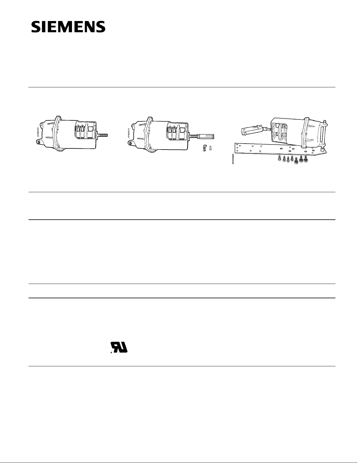
No. 6 Pneumatic Damper Actuator
Basic Actuator Typical Actuator with Clevis and Pin Actuator with Extended Shaft and
Description
Features
The No. 6 Pneumatic Damper Actuator is a heavy-duty, rolling diaphragm, spring return
actuator designed to drive large dampers, centrifugal fan inlet vanes, and other
applications requiring a large effective diaphragm area and long stroke.
• Replaceable ozone-resistant silicone rubber rolling diaphragm
• Safe for use in automotive industry applications
• Pivot mounting for extended shaft or frame mounting
OEM Literature
Frame Mounting Accessories
Product Numbers
Application
• Positioning relay (optional)
• Adjustable forward travel stops (optional)
• Three spring ranges
See Table 1
The No. 6 Pneumatic Damper Actuator is recommended for control of outdoor, return air,
exhaust, face and bypass, and fan discharge dampers. It is recommended for
heavy-duty applications using multi-section dampers where either unison or sequence
operation is required.
Certain actuators in Table 1 are UL Recognized Components under UL’s
Damper Actuator category (EMKU2). This category covers pneumatic
damper actuators used on fire dampers and fire/smoke leakage rated
dampers. Complies with UL's 400°F heated air requirements.
Siemens Building Technologies, Inc.
Page 2

Technical Instructions Powers™ Controls No. 6 Pneumatic Damper Actuator
Document Number 152-013P25
April 28, 2003
Table 1. Product Numbers for No. 6 Pneumatic Damper Actuators.
Description
Basic Actuator only Pivot 331-2793 331-2794
Basic Actuator only (Marine Finish) Pivot 331-2884
Actuator, with forward travel stops (Figure 1) Pivot – 331-2796 331-2988
Pivot Mount Actuator with clevis, clevis pin, and hitch
pin clip
Same as above with positioner (Figure 6) Pivot – – 332-2856
Actuator and manufacturing assembly for extended
shaft and frame mounting
Same as above with positioner (Figure 6) Universal kit with
Mounting Style
3-8 psi
(21-55 kPa)
Pivot 331-2857 331-2858
Universal kit 331-3012 331-3013
– – 332-3011
positioner
Part Number
Nominal Spring Range
3-13 psi
(21-90 kPa)
8-13 psi
(55-90 kPa)
331-3060*
331-2856*
331-3011*
* UL Recognized Component.
NOTE: Kits must be ordered separately from damper manufacturer.
Specifications
Effective Diaphragm Area 17.9 inch2 (115 cm2)
Stroke 4 inch (102 mm)
Housing Aluminum
Shaft Stainless steel
Diaphragm Ozone-resistant silicone rubber
(contains no migrating silicone lubricant)
Maximum Air Pressure 30 psig (210 kPa)
Nominal Spring Ranges 3 to 8 psi (21 to 55 kPa)
3 to 13 psi (21 to 90 kPa)
8 to 13 psi (55 to 90 kPa)
Ambient Temperature Range
Operating -20°F to 200°F (-29°C to 93°C)
Storage
Air Connection 1/8-inch NPT
Type of Mounting Pivot
Thrust and Torque Rating See Table 2
Dimensions See Figure 3 through Figure 6
Agency Approvals Complies with UL555 and UL555S
400°F heated air requirem ents
Table 2. Thrust Torque Ratings.
Nominal
Spring
Range
15psi
(103 kPa)
3-8 psi
(21-55 kPa)
3-13 psi
(21-90 kPa)
8-13 psi
(55-90 kPa)
* With maximum hysteresis of 2.5 psi (17.2 kPa) @ 90° rotation.
Page 2 Siemens Building Technologies, Inc.
125 (556) 179 (796) 304 (1352)
36 (160) 89 (396) 214 (952) 54 (240) 50 (5.6) 50 (5.6) 75 (8.5) 75 (8.5)
36 (160) 89 (396) 214 (952) 144 (640) 50 (5.6) 50 (5.6) 125 (14) 202 (23)
Maximum Thrust lbs. (N) Torque Rating* lb-in (Nm)
Full Stroke Forward 2-Position Operation
Spring
Return
18 psi
(124 kPa)
25 psi
(172 kPa)
(No Stroke)
0 psi (0 kPa)
54 (240) 50 (5.6) 75 (8.5) 75 (8.5) 75 (8.5)
Gradual
Operation
15 psi
(103 kPa)
or Positioner
18 psi
(124 kPa)
25 psi
(172 kPa)
Page 3

Powers™ Controls No. 6 Pneumatic Damper Actuator Technical Instructions
Document Number 152-013P25
April 28, 2003
NOTE: The No. 6 Pneumatic Damper Actuator does not require any periodic cycling. However, it is strongly
suggested that all systems are functionally checked periodically, and per local codes and ordinances.
Accessories
Damper shaft extension kits:
1/2-inch (13 mm) diameter (See TB-128) 331-631
1/2-inch (13 mm) diameter, 9-inch (229 mm) long,
hollow rod 333-184
1/2-inch (13 mm) diameter, 9-inch (229 mm) long 333-042
1-inch (25 mm) diameter, 11-5/8-inch (295 mm) long 333-194
Actuator shaft extensions:
10-1/8 inch (257 mm) long 331-434A
Adapter kit for 1/2 inch NPT pipe 333-030
Damper shaft extension kit adapter - 3/8 inch (9.5 mm) 331-632
Cranks—damper shaft:
3/8-inch (9.5 mm) - 1/2 inch (13 mm) diameter,
selectable radius 331-941
5/8-inch (16 mm) diameter 333-182
3/4-inch (19 mm) diameter 333-183
1-inch (25 mm) diameter 333-181
Cast iron crank with setscrews 333-078
Linkage kit (4-inch, 102 mm, link and crank) 331-958
Remote mounting kit (extended shaft) 331-618
Universal mounting plate
3/4-inch damper shaft 331-623
1-inch damper shaft (use with 333-194) 331-623A
Right angle mounting plate 333-208
Bearing 331-862
Positioning relay 147-2000
Positioning relay mounting kit 147-276
Mounting lug 331-569
Screws (three required for frame mounting lug) 034-123K
Offset mounting bracket 333-176
Travel stop rods 333-197
Service Kits
Siemens Building Technologies, Inc. Page 3
Diaphragms (Package of five) 333-572
Page 4

Technical Instructions Powers™ Controls No. 6 Pneumatic Damper Actuator
=
Document Number 152-013P25
April 28, 2003
Actuator Sizing
The quantity of actuators required depends on several torque factors. To determine
the quantity of actuators required for the installation:
• Obtain damper torque ratings (ft-lb/ft
2
) from the damper manufacturer.
• Determine the area of the damper.
• Calculate the total torque required to move the damper:
Total Torque = Torque Rating x Damper Area
• Calculate the total quantity of actuators required:
Number of Total Damper Torque Required
Safety Factor
Actuators
1
Safety Factor: When calculating the number of actuators required, a safety factor
SF1 x Actuator Torque (Table 2)
should be included for unaccountable variables such as slight misalignments, aging of
the damper, etc. A suggested safety factor is 0.80 (or 80% of the rated torque).
See AB-300 Damper Actuator Sizing and Selection Application Bulletin in the HVAC
Systems/Controls Reference Data (125-1853) for additional sizing information. See
TB-181 Powers™ Controls Maximum Thrust Ratings of Pneumatic Damper Actuators
Technical Bulletin (155-219P25) for additional torque requirements.
Operation
The air tubing from a controlling instrument is connected to the actuator’s upper housing.
With no control pressure to the actuator, the compression spring forces the spring seat
Standard Actuator
(Figure 1)
and actuator shaft toward the upper housing but is limited by the E”–ring. As the control
pressure increases, the spring compression is overcome and the actuator shaft
gradually moves outward. Conversely, as control pressure decreases, the spring returns
the shaft to the position at which the air pressure on the diaphragm balances the spring
tension. For each value of control pressure there is a corresponding position of the shaft
Table 3. Construction Components.
Item Part No. Description Qty. Material
1 047-061J Retaining E-ring 1 Steel
2 333-217 1 × 1-1/4 in. Hex Nut 1 Brass
3 — Spring Retainer 1 —
4 — Stem Guide Assembly 1 —
5 — Lower Housing 1 Aluminum
Diaphragm 1
5/16 in.-18 × 1
Large Hex Cap Screw
Piston Plate and Stem
Assembly
6 Steel
1
Silicone
rubber
Aluminum/
Stainless
Steel
Figure 1. Standard Actuator.
6
333-572
(pkg. of 5)
7 599-00413
8 — Upper Housing 1 Aluminum
9 — Helical Compression Spring 1
331-091 3 to 13 psi (21 to 90 kPa) —
331-208 3 to 8 psi (21 to 55 kPa) —
331-094 8 to 13 psi (55 to 90 kPa) —
10 —
11 — Retaining C-ring 1 Steel
12 333-197 Stop Kit (Optional) — Steel
Page 4 Siemens Building Technologies, Inc.
Page 5

Powers™ Controls No. 6 Pneumatic Damper Actuator Technical Instructions
Document Number 152-013P25
April 28, 2003
Operation,
Continued
Figure 2. Extended Shaft/Frame Mounting Actuator Assembly.
Table 4. Extended Shaft/Frame Mounting Assemblies.
Item Part No. Description Qty. Material
1 041-162J Nut 1 Steel
2 146-020K Lock washer 1 Steel
3 047-061K E-ring 2 Steel
4 331-565 Pivot post 1 Steel
5 041-142 Nut 1 Steel
6 333-207 Clevis 1 Zinc plated steel
7 331-293 Clevis pin 1 Zinc plated steel
8 331-807 Hitch pin 1 Zinc plated steel
9 331-941 Crank assembly 1 Zinc plated steel
10 331-623 Actuator mounting plate 1 Steel
— 034-283 Mounting screws 4 Steel
F 333-034 Rocker — Zinc plated steel
F 034-123K Mounting screws 3 Steel
F 041-230J Nut 2 Steel
F 030-510J Screws 2 Steel
“F” Parts for Frame Mounting.
Siemens Building Technologies, Inc. Page 5
Page 6

Technical Instructions Powers™ Controls No. 6 Pneumatic Damper Actuator
Document Number 152-013P25
April 28, 2003
Dimensions
Figure 3. Dimensions Shown in Inches (Millimeters).
Offset Mounting
Bracket
This bracket is designed to offset
the Universal Mounting Plate
331-623 or 331-623A from
ductwork.
NOTE: Depending on the
application, two
brackets may be
required to support the
actuator and universal
mounting plate.
Figure 4. Offset Mounting Bracket 331-176.
Dimension in Inches (Millimeters).
Figure 5. Actuator Mounting Plate.
Dimensions in Inches (Millimeters).
Page 6 Siemens Building Technologies, Inc.
Page 7

Powers™ Controls No. 6 Pneumatic Damper Actuator Technical Instructions
Document Number 152-013P25
April 28, 2003
Dimensions,
Continued
Figure 6. No. 6 Pneumatic Damper Actuator with the RL 147 Positioning Relay Mounted.
Dimensions in Inches (Millimeters).
Information in this publication is based on current specifications. The company reserves the right to make c hanges i n specifications and models as
design improvements are introduced. Powers is a trademark of Siemens Building Technologies, Inc. Other product or company names mentioned
herein may be the trademarks of their respective owners. © 2003 Siemens Building Technologi es, I nc.
Siemens Building Technologies, Inc.
1000 Deerfield Parkway
Buffalo Grove, IL 60089-4513
U.S.A.
Your feedback is important to us. If you have
comments about this document, please send
them to technical.editor@siemens.com
Document No. 152-013P25
Printed in the U.S.A.
Page 7
 Loading...