

Page 1
A111-3EN • 1/2009
VALV-POWR – VPVL double-opposed piston actuators
combine the benefits of high cycle life, a rugged construction, and an extremely compact and symmetrical
design with a unique range of features and options.
They are specifically designed for fast efficient operation of ball, butterfly, and other rotary type valves.
FEATURES
Single-Source Responsibility
■■
Valves,actuators, and accessories are designed to operate as a unit with the highest degree of compatibility.
■■
Valves, actuators, and accessories can be supplied
completely assembled to provide unit responsibility
from a single source.
Versatility
■■
Modular designs with same body and end caps for
double-acting and spring-return reduce inventory.
Springs can be added in the field to convert doubleacting to spring-return or for changes in supply pressure.
■■
Failure direction can be easily reversed from springto-open or spring-to-close orientation simply by
inverting the pistons.
■■
Actuator to valve attachments comply with ISO
5211/1 and EN 12116.
■■
Solenoid valve and accessory attachments comply
with NAMUR VDI/VDE 3845.
■■
A wide range of optional accessories and control
devices that include limit switches, solenoid valves,
and mechanical safety lockouts are available to satisfy
virtually all automated valve requirements.
■■
Several models of 180 degree VPVL’s are optionally
available.
High Cycle Life
■■
Bearings on all sliding and rotating moving parts to
ensure long life.
■■
Dual piston rack-and-pinion mechanism for simple
construction, high cycle life, and constant torque.
■■
Hard-anodized PTFE-coated extruded aluminum
body with honed internal surface for strength and
lower coefficient of friction.
■■
Mechanically multi-guided aluminum pistons for
precise movement, low friction, and high cycle life.
VALV-POWR® SERIES VPVL
MODEL C DOUBLE-ACTING
AND SPRING-RETURN RACKAND-PINION COMPACT
PNEUMATIC ACTUATORS
■■
Machined teeth on piston racks and pinions for
excellent rack and pinion engagement and maximum
efficiency.
Corrosion Resistant
■■
Hard-anodized PTFE-coated body, polyester-coated
end caps, and epoxy-coated springs, along with
internal and external stainless steel fasteners,
provide corrosion resistance in a variety of difficult
applications and environments.
Reliability
■■
Safety-contained multi-spring design with preloaded
and heavy-duty coated springs for simpler range
versatility,greater safety, and corrosion resistance.
■■
External adjustable stops in both directions assure
flexibility and accuracy when setting the valve in
the open and closed positions.
■■
As an added safety feature,the external adjustment
screws are slotted.The slot will indicate the presence
of internal pressure. Pressure will begin to vent
before the adjustment screws are completely
backed out of the actuator.
SPECIFICATIONS
Maximum Supply Range: 116 psi (8 bar)
Temperature Range:
Standard -4˚F to +175˚F (-20˚C to +80˚C)
Optional -40˚F to +300˚F (-40˚C to +150˚C)
Rotation Adjustment: -4˚ to +4˚; 86˚ to 94˚
Supply Media: Air, mineral-based hydraulic fluid
STANDARDS
Actuator to valve mounting: EN12116 ISO 5211/1
Actuator to solenoid mounting: Namur,VDI/VDE3845**
Actuator to accessory mounting: Namur, VDI/VDE3845*
* Except VPVL011 ** Except VPVL011,650,700, 800
Page 2
TECHNICAL BULLETIN 1/09
2
METSO A111-3EN
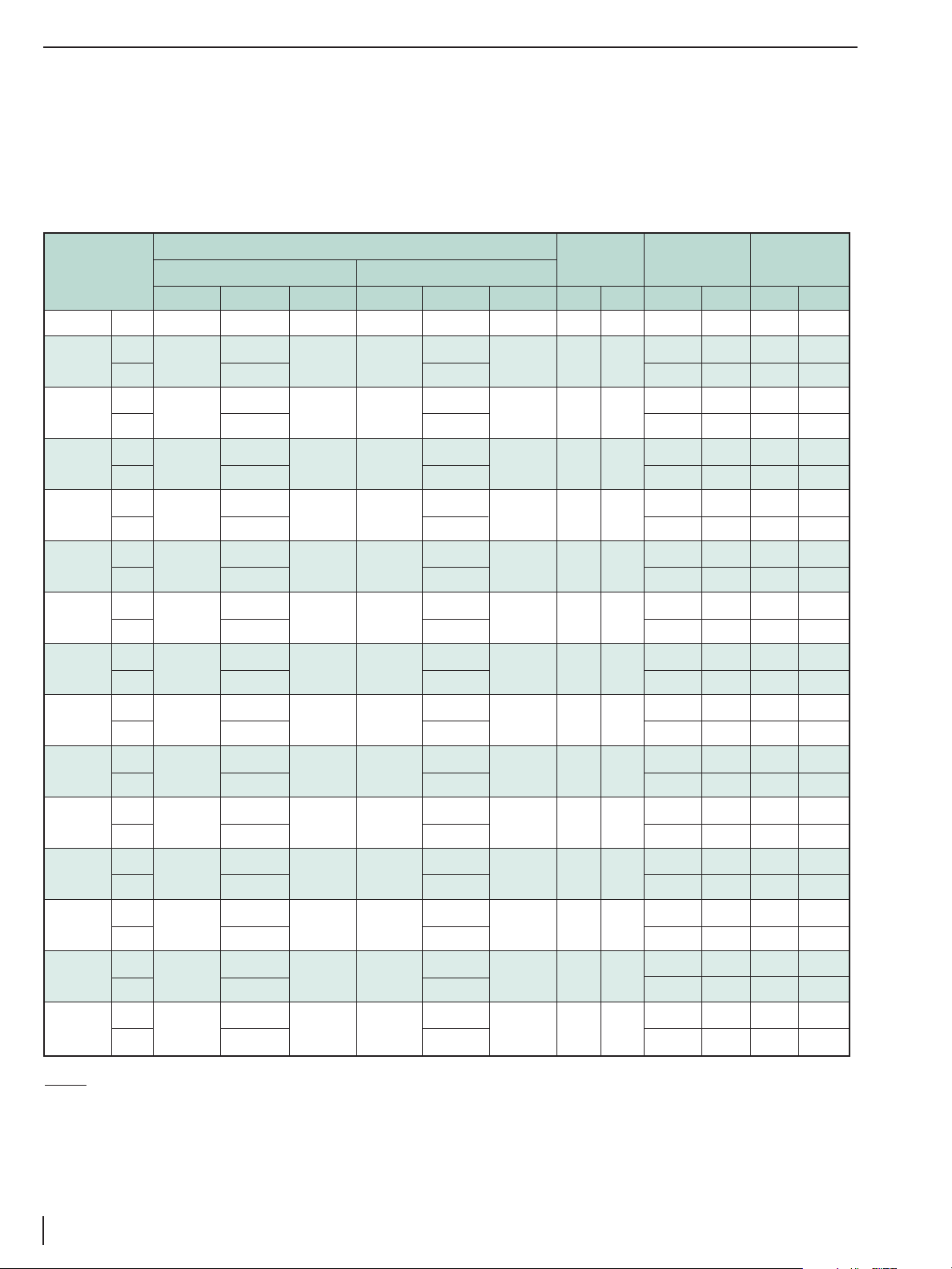
Air Volume
Moving Time
Actuator Model in.
3
ml
Bore Diam.
Seconds
1
Wei ght
Opening Closing Swept Opening Closing Swept in. mm Opening Closing lb. kg
VPVL011 DA 3.1 4 1.2 50.8 65.6 20.3 1.5 38 0.2 0.2 1.0 0.5
VPVL051
DA
5.5
9.2
3.4 90.1
150.8
55.5 1.97 50
0.2 0.3 2.1 1.0
SR – – 0.3 0.3 2.3 1.1
VPVL100
DA
9.8
15.9
6.0 160.6
260.6
97.8 2.48 63
0.3 0.3 3.3 1.5
SR – – 0.3 0.4 3.8 1.7
VPVL200
DA
18.9
29.9
11.8 309.7
490
194.1 2.95 75
0.3 0.4 5.9 2.7
SR – – 0.4 0.5 7.0 3.2
VPVL250
DA
31.1
47.6
18.6 509.6
780
305.4 3.46 88
0.4 0.5 8.4 3.8
SR – – 0.5 0.6 9.7 4.4
VPVL300
DA
43.3
67.7
27.1 709.6
1109
443.7 3.94 100
0.5 0.6 11.9 5.4
SR – – 0.7 0.9 14.3 6.5
VPVL350
DA
72.6
109.8
43.8 1190
1799
717.2 4.53 115
0.7 0.8 18.6 8.4
SR – – 0.9 1.1 21.7 9.8
VPVL400
DA
94
143
56 1540
2443
924 4.92 125
0.9 1.1 22.5 10.2
SR – – 1.2 1.4 27.8 12.6
VPVL450
DA
147
231
89 2409
3765
1451 5.71 145
1.2 1.4 32.0 14.5
SR – – 1.5 1.8 39.9 18.1
VPVL500
DA
192
300
116 3146
4916
1893 6.30 160
1.5 1.7 43.7 19.8
SR – – 1.8 2.1 52.9 24.0
VPVL550
DA
260
420
156 4261
6883
2556 7.09 180
2.0 2.2 55.1 25.0
SR – – 2.4 2.8 69.7 31.6
VPVL600
DA
362
577
217 5932
9455
3549 7.87 200
2.7 3.2 78.3 35.5
SR – – 3.5 4.0 99.4 45.1
VPVL650
DA
610
928
364 10000
15200
5963 9.45 240
3.5 4.0 115 53
SR – – 4.1 4.6 139 64
VPVL700
DA
885
1305
528 14503
21385
8655 10.43 265
4.0 4.5 183 83
SR – – 4.5 5.0 225 102
VPVL800
DA
1526
2441
917 25000
40000
15032 12.99 330
6.0 7.0 295 134
SR – – 7.5 8.5 373 169
To select an actuator for a particular valve and service,first
determine the maximum operating torque that will be
required from the applicable valve bulletin.Then refer to the
appropriate torque output table and select an actuator
that will, at the available supply pressure,provide a torque
output no less than the required operating torque for the
valve. For spring-return units, both the spring torque and
the air torque must be sufficient.In the event confirmation
is desired for the selection of an actuator under specific
service conditions,include full details on trim, seat materials,
and media characteristics.
ACTUATOR SELECTION
NOTES:
(1) The above times are based on the following conditions: A) Room temperature ,B) Solenoid valve orifice diameter of 4 mm (5/32 in.) and a flow rate
capacity of 400 L/min (14.1 cfm), C) Minimum inner piping diameter of 8 mm (5/16 in.),D) 5.5 bar (80 psi) air supply pressure, E) Without valve loading.
Page 3
TECHNICAL BULLETIN 5/08
3
VALV-POWR SERIES VPVL MODEL C DOUBLE-ACTING AND SPRING-RETURN RACK- AND-PINION COMPACT PNEUMATIC ACTUATORS
A111-3EN
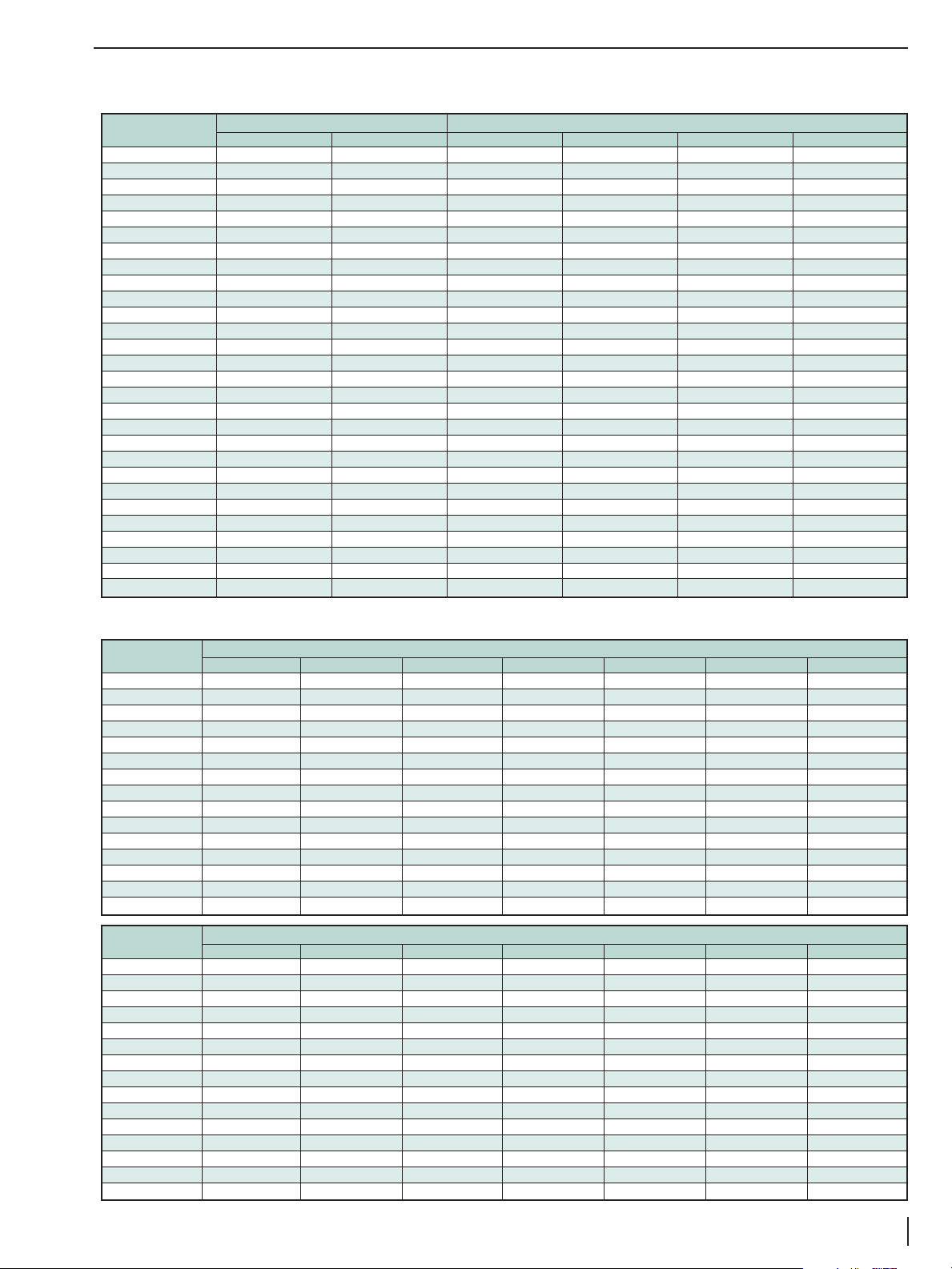
ACTUATOR SELECTION (CONTINUED)
SPRING RETURN
Actuator Spring-Return Torque Output Air Torque Output at Specified Supply Pressure
Model FT•LBS N•m FT•LBS, @ 60 psi N•m @ 4.2 bar FT•LBS @ 80 psi N•m @ 5.5 bar
051 SR4/5 4.5 6.1 3.7 4.9
051 SR6 6 8.1 4.9 6.6
100 SR4/5 7.4 10 6.7 8.5
100 SR6 9.8 13.3 8.9 12
200 SR4/5 14.7 19.9 12 17
200 SR6 19.6 26.5 16 22
250 SR4/5 24.3 33 17 24
250 SR6 32.5 44.5 23 32
300 SR4/5 33.6 45.6 28 40
300 SR6 44.9 60.8 38 51
350 SR4/5 54.4 73.8 44 62
350 SR6 72.6 98.4 58 79
400 SR4/5 69.7 95 59 84
400 SR6 93 126 79 107
450 SR4/5 109 148 94 133
450 SR6 146 198 126 169
500 SR4/5 149 202 126 178
500 SR6 199 269 168 225
550 SR4/5 210 285 153 278
550 SR6 280 379 204 274
600 SR4/5 282 383 231 327
600 SR6 376 510 308 414
650 SR4/5 479 649 399 541
650 SR6 638 865 532 721
700 SR4/5 724 981 520 737
700 SR6 966 1308 693 931
800 SR4/5 1221 1656 1105 1498
800 SR6 1628 2207 1473 1997
DOUBLE ACTING
Actuator Torque Output in FT•LBS - VPVL XXDA Double-Acting Actuator at Specified psi Supply Pressures
Model 40 psi 50 psi 60 psi 70 psi 80 psi 90 psi 100 psi
VPVL 011 DA 2.5 3.1 3.7 4.3 4.9 5.5 6.2
051 6.8 8.5 10.1 11.8 13.5 15.2 16.9
100 12 14.9 17.9 20.9 23.9 26.8 29.8
200 23.7 29.6 35 41 47 53 59
250 37.2 46.6 55 65 74 83 93
300 54 67.6 81 94 108 122 135
350 87.5 109 131 153 175 197 219
400 113 141 169 197 225 254 282
450 177 221 265 310 354 398 442
500 231 289 346 404 462 519 577
550 312 390 467 545 623 701 779
600 433 541 649 757 866 974 1082
650 727 909 1091 1272 1454 1636 1818
700 1055 1319 1583 1847 2111 2375 2638
800 1833 2291 2749 3207 3665 4123 4581
Actuator Torque Output in N•m - VPVL XXDA Double-Acting Actuator at Specified bar Supply Pressures
Model 2.7 bar 3.5 bar 4.2 bar 4.8 bar 5.5 bar 6.2 bar 6.9 bar
VPVL 011 DA 3.2 4.2 5.1 5.8 6.7 7.6 8.5
051 8.9 11.6 14 16 18.3 20.7 23
100 16 20.5 24.6 28.1 32 36 40
200 31 40 48 55 64 72 80
250 48 66 79 90 103 117 130
300 68 93 112 128 146 165 184
350 115 150 181 207 236 266 296
400 143 194 233 266 305 344 383
450 224 304 365 417 478 539 600
500 293 397 477 545 624 703 782
550 395 536 643 735 842 949 1056
600 575 745 893 1021 1170 1319 1468
650 986 1232 1479 1725 1971 2218 2465
700 1338 1815 2179 2490 2853 3216 3579
800 2485 3106 3727 4348 4969 5590 6211
Page 4

TECHNICAL BULLETIN 1/09
4
METSO A111-3EN
OPTIONS
Solenoid Valves
Direct-mounted solenoid valves are available in both 3-way
and 4-way configuration, which mount directly to the
actuator in accordance with NAMUR and VDI/VDE 3845
standards, excluding the VPVL011, 650, 700 and 800. In
general,3-way solenoids are used for spring-return actuators
and 4-way versions for double-acting.
NOTE: Please consult factory for other solenoid valves or additional options
including special voltages,double solenoids, special electrical connections,etc.
Mechanical Safety Lockout
To comply with the intent of OSHA requirements for locking actuators in position prior to performing maintenance,
an actuator can have the mechanical safety lockout option
added to it. Design of the stop cam allows for locking the
actuator in either the full-open or full-closed position.
Actuators equipped with this option have a special lockout
screw and a tamperproof cover attached to the housing of
the actuator with stainless steel wire. The lockout kits are
readily available to permanently lock the actuator in place
to prevent unwanted operation.
100% Adjustable Travel Stop
To limit the rotation on the stroke beyond the standard
±4˚ of a VPVL actuator, a stainless steel 100%-adjustable
travel stop option can be added.The stops, located in the
Direct-Mount Solenoid Valves
Part Number 031-0576-01 031-0580-01
Enclosure NEMA IV NEMA VII
Configuration 3 or 4-way
Pipe Size 1/4" Inlet, 1/8" Exhaust
Cv 0.7
Voltage Standard: 120 VAC 60 Hz (110/50)
Optional: 240 VAC 60 Hz, 12 VDC, 24 VDC
Body Material Black Anodized Aluminum
Power Consumption AC: 6.9 watts
DC: 6.3 watts
end caps, allow the valve position to be set anywhere
between full closed and full open. This option limits travel
of only the counter-clockwise stroke for standard doubleacting and spring-closed units. The 100% Adjustable Stop
option is specified in the actuator ordering code.
Special longer bolt used to
lock the actuator in one
position when needed.
Lockout Kits
VPVL051 LD78
VPVL100 LD79
VPVL200 LD80
VPVL250 LD81
VPVL300 LD82
VPVL350 LD83
VPVL400 LD84
VPVL450 LD85
VPVL500 LD86
VPVL550 LD87
VPVL600 LD88
VPVL650 LD89
VPVL700 LD90
VPVL800 LD91
100% Travel Stop Lengths
Actuator
L Min L Max
inch mm inch mm
VPVL051 6.2 158 7.3 186
VPVL100 7.2 184 8.5 216
VPVL200 9.5 242 11.3 286
VPVL250 11.0 280 13.0 330
VPVL300 11.9 303 14.1 359
VPVL350 14.0 356 16.7 424
VPVL400 14.5 368 17.5 444
VPVL450 17.7 449 21.1 537
VPVL500 18.1 461 21.9 555
VPVL550 20.9 531 24.8 631
VPVL600 24.7 628 29.1 739
VPVL650 25.7 653 30.9 785
VPVL700 30.0 762 36.1 918
VPVL800 35.8 910 42.8 1086
Stop Screw
Type A
VPVL051-300
Stop Screw
Type B
VPVL350-800
L Min. Approx.
L Max. Approx.
Page 5

TECHNICAL BULLETIN 5/08
5
VALV-POWR SERIES VPVL MODEL C DOUBLE-ACTING AND SPRING-RETURN RACK- AND-PINION COMPACT PNEUMATIC ACTUATORS
A111-3EN
Declutchable Manual Override
A side-declutchable manual override is available for VPVL
actuators. It consists of a manual gear actuator mounted
between the actuator and the valve.The device is normally
disengaged from the shaft. Upon engagement of the
override clutch, overriding the actuator is done with ease,
aided by the high-reduction ratio of the manual gear unit.
VPVL Actuator Declutchable
Approximate Dimensions - Inches
Model Override
Approx.
(DA or SR) Kit
BCDE FGHJ SWeight
lbs.
VPVL250 and VPVL300 DO-1 5.75 6.89 5.61 2.36 4.53 1.44 8.94 7.87 0.47 22
VPVL350 and VPVL400 DO-2 7.68 9.49 6.06 2.48 5.63 2.09 10.28 7.87 0.59 40
VPVL450 and VPVL500 DO-3 8.74 11.12 7.46 3.31 6.30 2.48 10.63 11.81 0.79 50
VPVL550 and VPVL600 DO-4 9.84 12.84 9.00 4.23 6.77 2.36 13.31 19.69 0.79 84
VPVL650 and VPVL700* DO-5 10.87 14.45 10.16 5.00 7.48 2.68 14.41 35.43 0.98 141
VPVL800 DO-6 13.39 16.69 12.32 6.06 8.07 3.07 15.63 39.37 0.98 201
VPVL Actuator Declutchable
Approximate Dimensions - mm
Model Override
Approx.
(DA or SR) Kit
BCDE FGHJ SWeight
kgs.
VPVL250 and VPVL300 DO-1 146 175 142 60 115 37 227 200 12 10
VPVL350 and VPVL400 DO-2 195 241 154 63 143 53 261 200 15 18
VPVL450 and VPVL500 DO-3 222 282 190 84 160 63 270 300 20 23
VPVL550 and VPVL600 DO-4 250 326 228 107 172 60 338 500 20 38
VPVL650 and VPVL700* DO-5 276 367 258 127 190 68 366 900 25 64
VPVL800 DO-6 340 424 313 154 205 78 397 1000 25 91
* The VPVL700 DA unit may be used if the air pressure required to produce the needed output torque is lower than 95 psi.
* The VPVL700 DA unit may be used if the air pressure required to produce the needed output torque is lower than 6.5 bar.
Actuator
Mounting
Side
F B
G
J
S
H
E
D
C
DIMENSIONS
Page 6

TECHNICAL BULLETIN 1/09
6
METSO A111-3EN
DIMENSIONS
Model VPVL 051 – 800
C
L
I
H
C
4
Z
B
M
L
M
B
4
BottomView ISO5211
T Connection
Detail X
Detail X
Port 4
Port 2
R
S
D
M5xE
G
F
N
M6x12
N
P
4
12
M6
12
X P Y
A
45˚
45˚
W
CH
Q
Model VPVL011
B1
R
S
D
Port 2
Port 4
Port 2
Port 4
VPVL 011, 650 – 800VPVL 051 – 600
Page 7

TECHNICAL BULLETIN 5/08
7
VALV-POWR SERIES VPVL MODEL C DOUBLE-ACTING AND SPRING-RETURN RACK- AND-PINION COMPACT PNEUMATIC ACTUATORS
A111-3EN
Size
Dimensions- inches / lb.
ISO Weight
A B B1 C D E F G H I L M N O P Q R S W X Y T NPT
Flange
CH Z
DA SR
011 4.50 1.70 0.00 1.70 M5x4 0.28 1.97 0.98 0.79 0.39 0.80 0.80 0.43 - 0.79 1.40 0.94 1.26 M5 0.57 0.32 1/8 F03 0.35 1.57 1.0 -
051 5.53 2.72 1.36 2.32 M5x8 0.16 3.15 1.18 0.98 0.47 1.14 1.63 0.43 1.04 0.79 1.40 1.26 0.94 M5 0.57 0.31 1/8 F03 0.43 1.57 2.1 2.3
100 6.24 3.35 1.67 2.83 M5x8 0.31 3.15 1.18 1.38 0.63 1.42 1.85 0.43 1.18 0.79 1.97 1.26 0.94 M6 0.57 0.31 1/8 F05 0.55 1.57 3.3 3.8
200 8.29 4.02 2.01 3.33 M5x8 0.31 3.15 1.18 1.38 0.63 1.67 2.05 0.67 1.20 0.79 1.97 1.26 0.94 M6 0.57 0.31 1/8 F05 0.55 1.57 5.9 7.0
250 9.74 4.53 2.26 3.84 M5x8 0.31 3.15 1.18 2.17 0.83 1.95 2.24 0.67 1.28 0.79 2.76 1.26 0.94 M8 0.57 0.31 1/8 F07 0.75 1.57 8.4 9.7
300 10.57 5.00 2.50 4.37 M5x8 0.31 3.15 1.18 2.17 0.83 2.20 2.64 0.67 1.48 0.79 2.76 1.26 0.94 M8 0.57 0.31 1/4 F07 0.75 1.57 11.9 14.3
350 12.40 5.71 2.85 5.00 M5x8 0.31 3.15 1.18 2.76 0.94 2.52 3.03 1.06 1.67 1.18 4.02 1.26 0.94 M10 0.96 0.57 1/4 F10 0.87 2.20 18.5 21.7
400 13.58 6.18 3.09 5.35 M5x8 0.31 3.15 1.18 2.76 0.94 2.74 3.23 1.06 1.77 1.18 4.02 1.26 0.94 M10 0.96 0.57 1/4 F10 0.87 2.20 22.5 27.8
450 16.08 6.97 3.88 6.16 M5x8 0.31 3.15 1.18 3.35 1.38 3.15 3.60 1.06 1.85 1.18 4.92 1.26 0.94 M12 0.96 0.57 1/4 F12 1.06 2.56 32 40
500 17.22 7.72 3.86 6.65 M5x8 0.31 3.15 1.18 3.35 1.38 3.46 3.90 1.06 2.05 1.18 4.92 1.26 0.94 M12 0.96 0.57 1/4 F12 1.06 2.56 44 53
550 19.17 8.68 4.39 7.51 M5x8 0.31 5.12 1.18 3.94 1.57 3.90 4.13 1.42 2.28 1.97 5.51 1.26 0.94 M16 1.75 0.79 1/4 F14 1.42 3.15 55 70
600 21.38 9.65 4.80 8.39 M5x8 0.31 5.12 1.18 3.94 1.57 4.33 4.41 1.42 2.44 1.97 5.51 1.26 0.94 M16 1.75 0.79 1/4 F14 1.42 3.15 78 99
650 24.45 11.75 5.93 9.88 M6x10 0.31 5.12 1.18 5.12 1.89 5.16 5.16 1.42 3.09 1.97 6.50 1.57 1.77 M20 1.75 0.79 3/8 F16 1.81 4.53 115 139
700 26.93 12.99 6.50 11.75 M6x10 0.31 5.12 1.18 5.12 1.97 6.44 6.54 1.42 6.50 1.97 6.50 1.57 1.77 M20 1.75 0.79 1/2 F16 1.81 4.53 183 225
800 34.39 16.14 6.50 15.08 M6x10 0.31 5.12 1.18 7.87 2.24 8.03 8.43 1.42 7.28 1.97 10.00 1.57 1.77 M16 1.75 0.79 1/2 F25 2.17 4.53 295 373
Size
Dimensions- mm / kg
ISO Weight
A B B1 C D E F G H I L M N O P Q R S W X Y T NPT
Flange
CH Z
DA SR
011 114 43 0.0 43 M5x4 7 50 25 20 10 20 20 11 - 20 36 24 32 M5 14.5 8.0 1/8 F03 9 40 0.45 -
051 140 69 34.5 59 M5x8 4 80 30 25 12 29 41 11 26 20 36 32 24 M5 14.5 8.0 1/8 F03 11 40 0.95 1.04
100 158 85 42.5 72 M5x8 8 80 30 35 16 36 47 11 30 20 50 32 24 M6 14.5 8.0 1/8 F05 14 40 1.5 1.7
200 211 102 51.0 85 M5x8 8 80 30 35 16 42 52 17 30 20 50 32 24 M6 14.5 8.0 1/8 F05 14 40 2.7 3.2
250 247 115 57.5 98 M5x8 8 80 30 55 21 50 57 17 33 20 70 32 24 M8 14.5 8.0 1/8 F07 19 40 3.8 4.4
300 268 127 63.5 111 M5x8 8 80 30 55 21 56 67 17 38 20 70 32 24 M8 14.5 8.0 1/4 F07 19 40 5.4 6.5
350 315 145 72.5 127 M5x8 8 80 30 70 24 64 77 27 42 30 102 32 24 M10 24.5 14.5 1/4 F10 22 56 8.4 9.8
400 345 157 78.5 136 M5x8 9 80 30 70 24 70 82 27 45 30 102 32 24 M10 24.5 14.5 1/4 F10 22 56 10 13
450 408 177 98.5 156 M5x8 8 80 30 85 35 80 91 27 47 30 125 32 24 M12 24.5 14.5 1/4 F12 27 65 15 18
500 437 196 98.0 169 M5x8 8 80 30 85 35 88 99 27 52 30 125 32 24 M12 24.5 14.5 1/4 F12 27 65 20 24
550 487 220 111.5 191 M5x8 8 130 30 100 40 99 105 36 58 50 140 32 24 M16 44.5 20.0 1/4 F14 36 80 25 32
600 543 245 122.0 213 M5x8 8 130 30 100 40 110 112 36 62 50 140 32 24 M16 44.5 20.0 1/4 F14 36 80 35 45
650 621 298 150.5 251 M6x10 8 130 30 130 48 131 131 36 78 50 165 40 45 M20 44.5 20.0 3/8 F16 46 115 53 64
700 684 330 165.0 298 M6x10 8 130 30 130 50 164 166 36 165 50 165 40 45 M20 44.5 20.0 1/2 F16 46 115 83 102
800 876 410 165.0 383 M6x10 8 130 30 200 57 204 214 36 185 50 254 40 45 M16 44.5 20.0 1/2 F25 55 115 134 169
Page 8

TECHNICAL BULLETIN 1/09
8
METSO A111-3EN
No. Unit Qty Part Description Material Specifications
Corrosion
Protection
1 1 Octi-Cam (Stop Arrangement) Stainless Steel
1
EN 10088-3/ISO 1083
1
2 2 Stop Cap Screw Stainless Steel ASTM A193
3 2 Washer (Stop Cap Screw) Stainless Steel ISO 3506
4 2 Nut (Stop Cap Screw) Stainless Steel ISO 3506
5* 2 Bearing (Piston Back) Polyphthalamide Amodel ET1001HS
6* 1 Bearing (Pinion Top) Polyetherimide Stanyl TW300
7* 1 Bearing (Pinion Bottom) Polyetherimide Stanyl TW300
8* 2 Thrust Bearing (Pinion) Polyphthalamide Amodel ET1001HS
9* 2 Plug (Transfer Port) Nitrile Rubber NBR 70Shore A
10 1 Thrust Washer (Pinion) Stainless Steel EN 10088-3
11* 2 O-ring (Stop Cap Screw Seal) Nitrile Rubber NBR 70Shore A
12 2 Piston Guide Polyphthalamide GF Amodel AS1145
13 8/12/
2
Cap Screw (End Cap) Stainless Steel ISO 3506
14* 2 O-ring (End Cap) Nitrile Rubber NBR 70Shore A
15* 2 Bearing (Piston Head) Polyphthalamide Amodel ET1001HS
16* 2 O-ring (Piston) Nitrile Rubber NBR 70Shore A
17 min. 4/ max.12 Spring (Cartridge) Alloy Steel DIN 17223 Part2 Epoxy Coated
18 1 Spring Clip (Pinion) Carbon Steel DIN 17222 ENP
19 1 Position Indicator Polypropylene GF Hostalen PPN
20* 1 O-ring (Pinion Bottom) Nitrile Rubber NBR 70Shore A
21* 1 O-ring (Pinion Top) Nitrile Rubber NBR 70Shore A
30 1
3
Right End Cap
3
Aluminum UNI 5075 Polyester-Coated
31 1
3
Left End Cap
3
Aluminum UNI 5075 Polyester-Coated
39 1 Cap Screw (Indicator) Stainless Steel ISO 3506
40 2 Pistons Aluminum UNI 5075 Anodized
41 1 Actuator Identification Label Polyester Aluminum
42 2 End Cap Label Polyester Aluminum
50 1 Body Aluminum ASTM B221
Anodized
PTFE-Coated
60 1 Drive Shaft Carbon Steel Plated ASTM A105 ENP
5*
BILL OF MATERIALS AND PARTS LIST
50
41 10 18
39
19
8*
30
11*
3
2
4
17
7*
60
6*
21*
1
9*124016*
15*
14*
8*
31
42
13
20*
* Suggested Spare Parts
for Maintenance
* Suggested spare parts for maintenance
Notes: (1) AISI 420 for models VPVL-051 through 300; GS400-15 for models VPVL-350 through 800
(2) Qty 8 pieces for models VPVL-051 through 600; Qty 12 pieces for model VPVL-700
(3) For models VPVL500 through VPVL700, right and left end-caps are symmetric
Page 9

TECHNICAL BULLETIN 5/08
9
VALV-POWR SERIES VPVL MODEL C DOUBLE-ACTING AND SPRING-RETURN RACK- AND-PINION COMPACT PNEUMATIC ACTUATORS
A111-3EN
HOW TO ORDER
To specify a complete VALV-POWR VALUE-LINE Actuator, simply make a selection from the code boxes below.
EX
AMPLE: VPVL 400 SR4/5 B AS C, shown below, is a 59 FT•LBS 60-psi (84 N•m @ 4.2 bar) spring-return actuator with
spring-to-close rotation, hard-anodized PTFE-coated body, polyester-coated end caps, standard temperature rating, and
100% adjustable travel stops.
1
Product Group
VPVL VALV-POWR VALUE-LINE Double-Opposed Piston Actuator
4
Exterior Protection*
B
Hard-Anodized PTFE-Coated Body &
Polyester-Coated End Caps
123456
VPVL 400 SR4/5 B AS C
3
Series+
DA VALV-POWR VALUE-LINEDouble-Opposed Piston Actuator
SR4/5 Spring-Return 60-psi (4.1 bar) Spring-to-Close (CW Rotation)
SR6 Spring-Return 80-psi (5.5 bar) Spring-to-Close (CW Rotation)
2
Size
011, 051,
100, 200,
250, 300,
350, 400,
Select from torque table
450, 500,
550, 600,
650, 700,
800
5 Options
– Standard Temperature Rating: -4˚F to +175˚F (-20˚C to +80˚C)
HT High-Temperature Rating: -4˚F to +300˚F (-20˚C to +150˚C)
LT Low-Temperature Rating: -40˚F to +175˚F (-40˚C to +80˚C)
LX Low-Temperature Rating:-60˚F to +175˚F (-51˚C to +80˚C)
FO Spring-to-Open (CCW Rotation)
AS 100% Travel Stop
LD Mechanical Safety Lockout
NOTE: for multiple options, specify them in order as listed in Item 5, for example:VPVL400 SR4/5 B HT AS Model C.
+ Other spring rates on application
* Consult factory for other protection options.
6
Model
C Model C
7
Modifier Code
– Standard
XB ATEX Approval
7
—
Note* “LX” option must be ordered complete from the factory.
Page 10

Subject to change without prior notice.
Metso Automation Inc.
Europe, Levytie 6, P.O. Box 310, 00811 Helsinki, Finland.
Tel. +358 20 483 150. Fax +358 20 483 151
North America, 44 Bowditch Drive, P.O. Box 8044, Shrewsbury, MA 01545, USA.
Tel. +1 508 852 0200. Fax +1 508 852 8172
Europe, 6-8 rue du Maine, 68271 Wittenheim Cedex, France.
Tel. +33 (0)3 89 50 64 00. Fax +33 (0)3 89 50 64 40
South America, Av. Independéncia, 2500- Iporanga, 18087-101, Sorocaba-São Paulo
Brazil. Tel. +55 15 2102 9700. Fax +55 15 2102 9748/49
Asia Pacific, 238A Thomson Road, #25-09 Novena Square Tower A, 307684 Singapore.
Tel. +65 6511 1011. Fax +65 6250 0830
China, 19/F, the Exchange Beijing, No. 118, Jianguo Lu Yi, Chaoyang Dist, 100022 Beijing, China.
Tel. +86-10-6566-6600. Fax +86-10-6566-2575
Middle East, Roundabout 8, Unit AB-07, P.O. Box 17175, Jebel Ali Freezone, Dubai,
United Arab Emirates. Tel. +971 4 883 6974. Fax +971 4 883 6836
www.metso.com/automation
 Loading...