

Page 1
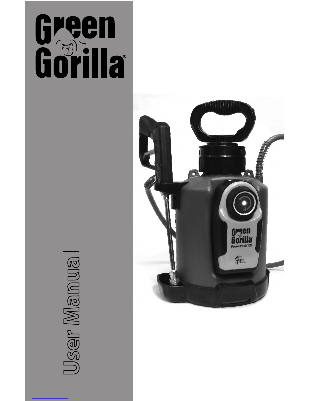
ProLine Em Industrial System
User Manual
#C-08-PL-00557
*P-01-PL-00528 shown, your system may vary
Page 2

Table of Contents
Safety Rules
System Compatibility
PowerPack Components
Tank Components
Wand & Tip Assembly
Wand Styles
Wand Handle Assembly
Wand Extension Assembly
AC70 Extension Assembly
Pro31 Extension Assembly
Tip Styles
Tip Assembly
Pro31 Tip Assembly
PS30 Tip Assembly
PowerPack Operation
PowerPack Attachment
PowerPack Removal
PowerPack Charging
PowerPack Usage
Tank Operation
Filling
Pressure Relief System
Cleaning & Maintenance
Tank Replacement Parts
PowerPack Replacement Parts
Warranty & Contact Information
2
3
3
4
5
5
6
6
6
7
8
8
9
10
11
11
11
12
13
14
14
15
16
17
18
19
Section Title Page
Pg. 1
Page 3

Congratulations on purchasing the rst intelligent compressed air spray system. With
the Green Gorilla ProLine Spray System you now have precision control when applying your product. Your Green Gorilla ProLine tank is equipped with a patented
Quick-Connect tting that allows the PowerPack to easily attach to the tank,
completely automating the pressurization process and precisely controlling the
pressure using Smart Pressure Technology (SPT™).
The instructions and maintenance tips provided in this owner's guide will assist you in
the care of your Green gorilla ProLine tank. Be sure to read all warnings and follow all
instructions before using the sprayer.
Warning and Cautionary Statements
Warning: When using solvent based products ensure the area is well ventilated with no open ames.
Fumes generated by certain products can be injurious to your health. Always operate the sprayer in
well ventilated areas and don protective equipment per the manufacturer’s recommendations for the
product being delivered. Never spray solvent based products in an enclosed area.
Warning: Never charge the PowerPack in temperatures below 32° F or above 110° F. This can result in
battery damage and/or re.
Warning: It is imperative that the original charger for the Green Gorilla system is used as dierent
chargers may not have the built in protection necessary to ensure a safe charging condition.
Warning: Do not pressurize the tank with anything other than genuine Green Gorilla parts and
accessories.
Warning: Do not use mechanical devices to pressurize tank other than recommended Green Gorilla
Power Packs and accessories.
Warning: Do not stand over tank while tank is pressurized. Securely tighten hand pump as instructed; a
loose pump could be forcibly ejected.
Warning: Do not alter or plug Quick-Connect valve, sprayer could explode. This is a safety device.
Caution: Do not ll tank above listed operating capacity.
Caution: Do not pressurize sprayer until ready to use or leave pressurized sprayer unattended.
Caution: Do not lift or carry sprayer by hose.
Caution: Do not use solutions hotter than 105° F. Damage may occur.
Important: Triple rinse tank and pressure relief valve between chemical change outs to ensure no cross
contamination.
Caution: Do not store outdoors or leave PowerPack in the rain. PowerPack is water resistant
but not water proof.
Warning: Do not charge the PowerPack in the rain or damp location. Charge in warm, dry location only.
Pg. 2
!
!
!
!
!
!
!
!
Safety Rules
Page 4
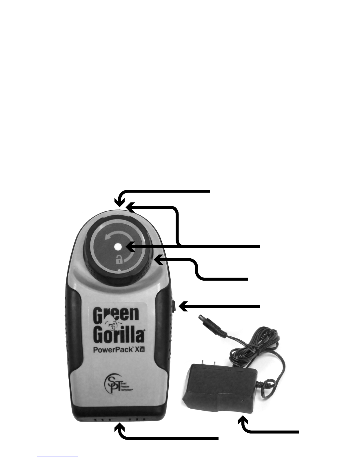
PowerPack Components
System Compatibility
PowerPack
Release Knob
PowerPack On/Off Switch
Charger with
Indicator Light
Charging Port & Cover
Battery Level Indicators
Carefully unpack the tank, PowerPack, and all loose items from the carton
and assemble as outlined in this guide.
Pg. 3
g. 1
Air Inlet Vents
IMPORTANT! This system should not be used with petroleum based solvents as
accelerated damage to the seals will occur. This system includes EPDM seals that
are most appropriate for acetone and water based products. Solvents such as
Xylene and Naphtha SHOULD NOT BE USED with the seals in this system.
Acetone based products should only be used in a well ventilated area.
Page 5

Tank Components
Carefully unpack the tank, PowerPack, and all loose items from the carton
and assemble as outlined in this guide.
Tank Body
Manual Pump Handle
Strain Relief
Springs
Hose Quick
Disconnect
Wand Holder
Wand Extension
Strongback Seals
Tank Base
g. 2
Pg. 4
Varies by
System
Wand Handle
Varies by
System
Size Varies
by System
(2.5 Gal. Shown)
Quick Connect Adaptor
& Pressure Relief Valve
PowerPack
Mounting Recess
Page 6

Your system can be congured with one of three dierent wand types, Figure 3
below identies each wand style. To complete the wand extension and tip
assembly you will need a 13/16" and 9/16" open end wrench. Note: Some systems
are pre-assembled, and require no additional assembly.
Wand & Tip Assembly
Pro31 PS30 AC70
Pro31: The Pro31 wand handle incorporates a shuto valve at the handle and is
typically equipped with an 8” curved end extension for the 1.5 gallon tank size
and the 18” curved end extension for the 2.5 gallon tank This wand incorporates
a strainer at the end of the wand extension as outlined in Figure 18 and requires
periodic maintenance to clean the lter/strainer. Figures 4 & 5 and Figures 7-11
detail the assembly process of the extension and tank hose.
PS30: The PS30 wand is a drip-less style wand with a positive shuto valve at the
tip. The shuto is controlled by a solid rod that runs down the length of the wand
extension. The wand extension is assembled at the factory and tested. The 1.5
gallon tank size typically comes with an 8” wand extension and the 2.5 gallon tank
size with an 18” wand extension. Figures 21 - 25 detail the assembly steps for the
tip.
AC70: TheAC70 is an all poly trigger valve style wand and can be equipped with
many dierent straight extension lengths. This wand commonly comes with the
15” straight wand extension. Figure 6 details the wand extension assembly.
Pg. 5
Wand Handle Styles
g. 3
Page 7
AC70: TheAC70 wand extension is assembled to the AC70 wand handle as outlined
in Figure 6. The tip will be preinstalled.
Pro31: Figures 16 - 20 detail the assembly of the Style A or B tip to the Pro31 wand
extension. The Pro31 wand extension is assembled to the Pro31 wand handle as
outlined in Figures 7 - 11.
PS30: The PS30 Wand extension is assembled at the factory and tested. No assembly is required.
Wand Extension Assembly
AC70 Extension
Assembly
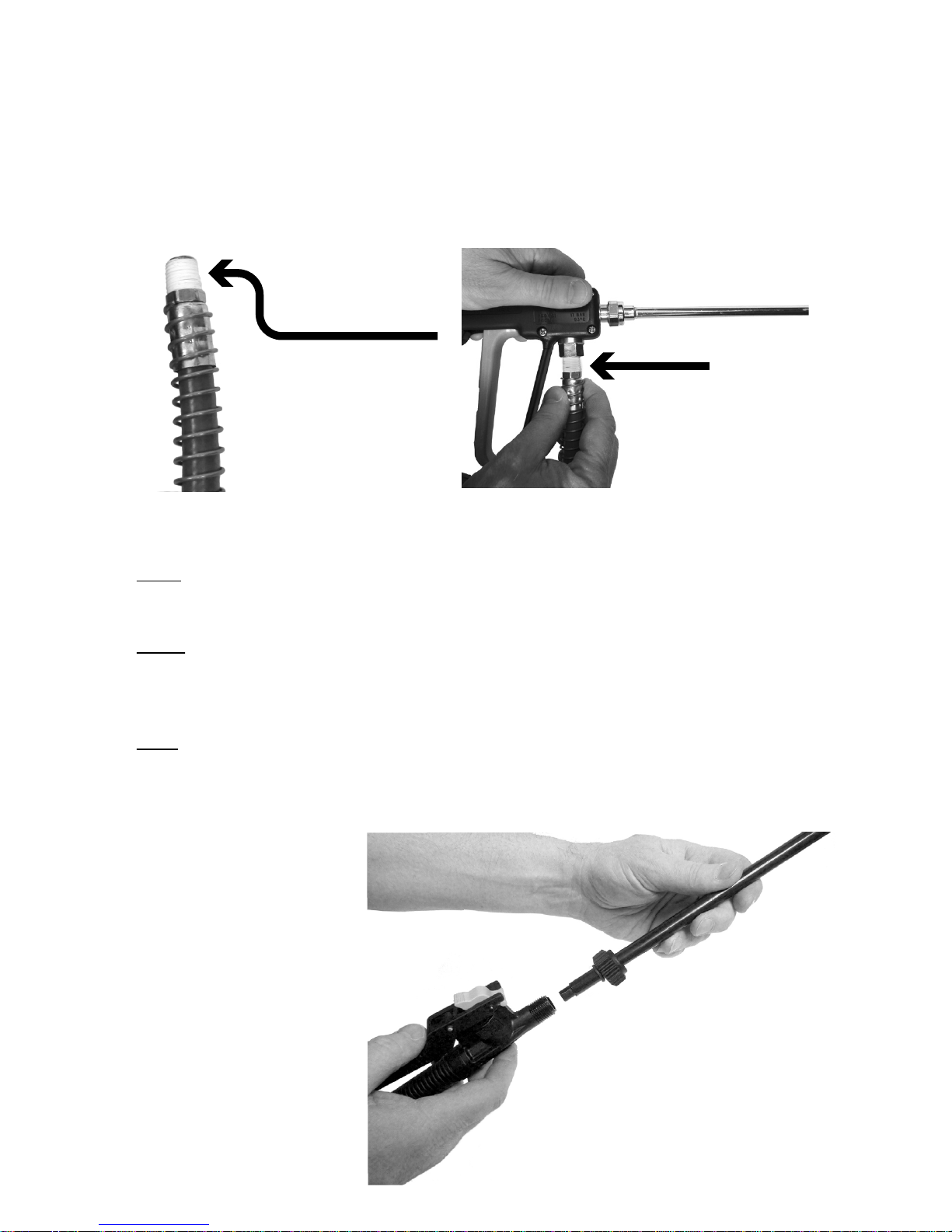
Assemble the wand
extension to wand handle.
Tighten the wand extension nut by hand in the
clockwise direction to
ensure a tight seal
between seating surfaces.
Securely hold the wand
handle in place while
tightening.
Do not over tighten.
Pg. 6
Wand Handle Assembly
To attach your wand handle to the tank, a 9/16” wrench is required. The 1/4” NPT
wand hose tting is pre-wrapped with Teon tape to ensure a leak tight joint.
Thread the wand hose tting into the end of the wand handle and tighten in a
clockwise direction using the 9/16” wrench. All Green Gorilla tank hoses and wand
handles use the standard 1/4” NPT tting.
Wand Hose Fitting
g. 4
g. 5
g. 6
Page 8
Pro31 Extension Assembly
Set Teon shuto at extension opening, while keeping the plunger drawn back
(as shown in gure 9).
Pg. 7
g. 7 g. 8
g. 9 g. 10
g. 11
Rest the o-ring on the Teon shuto, while keeping plunger drawn back (as
shown in gure 10)
Lastly, thread on the wand extension and securely tighten in
the clockwise direction (as shown in gure 11), and work the
spray trigger 2-3 times before nally releasing it. Tighten the
brass nut using a 13/16” wrench.
Assemble wand extension to wand handle. Draw back spray handle trigger to
retract the shuto valve at the extension opening (as shown below in gures 7 &
8). Hold trigger in place and assemble the Teon seal and o-ring as shown in
gures 9 & 10.
Page 9
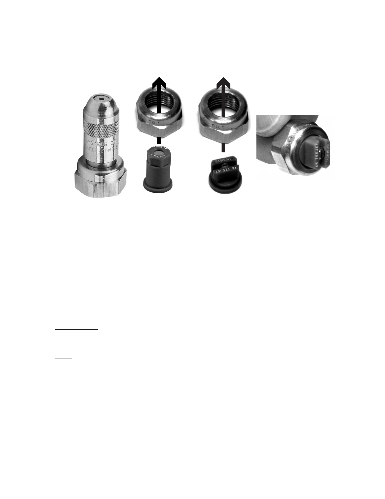
There are two styles of tip assemblies; Style A - adjustable pin to cone (Figure 12)
and Style B -pattern specic (Figures 13 & 14). The Style B pattern specic tip
assembly is detailed in Figure 15 (typical).
Tip Styles
Tip Assembly
For the style B tip shown in gures 13 & 14 (which includes specialty tips such as
fan patterns, cone patterns, and directional patterns), ensure that the tip aligns
and seats correctly into the brass nut.
IMPORTANT! The clearance between the brass nut and the tip is close. Care
should be taken when inserting the tip into the brass nut for proper seating.
TJ66 & Pro31: Figures 16 - 20 detail the Style A or B tip assembly to the TJ66 or
Pro31 wand extension.
PS30: Figures 21 - 25 detail the style A or B tip assembly to the PS30 wand extension.
Pg. 8
g. 12 g. 13 g. 14
g. 15
Page 10
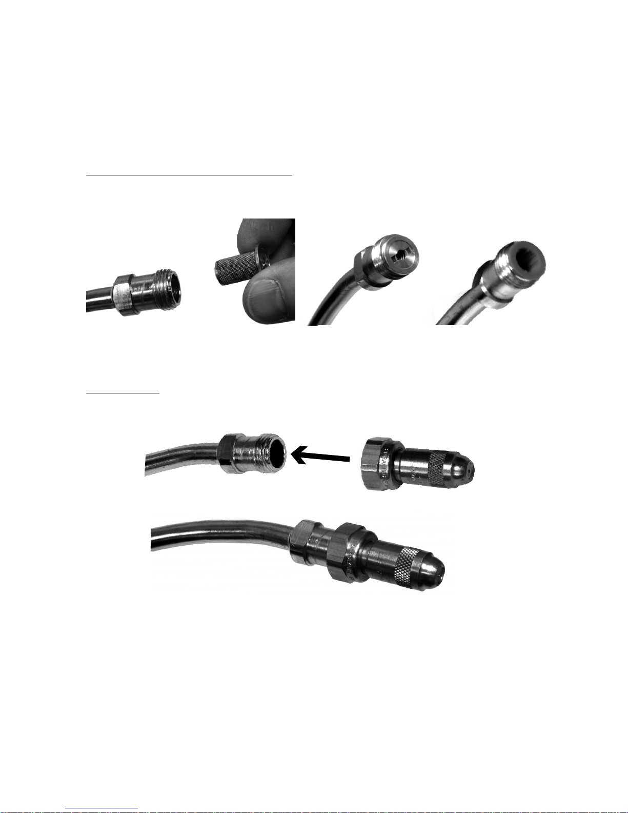
TJ66 & Pro31 Tip Assembly
Assembly of the tip and optional strainer is identical for both the TJ66 and the
Pro31 wand handle assembly.
Optional Strainers & Strainer/Shutos: Assemble optional strainer (if so equipped),
by inserting strainer into the end of the wand extension, as shown in gures 16 - 18.
Pg. 9
Strainer/Shutoff Strainer
g. 16
g. 17 g. 18
g. 19
g. 20
Tip Assembly: Thread the 13/16” brass nut onto the end of the wand extension
and tighten in the clockwise direction using a 13/16” wrench.
Page 11
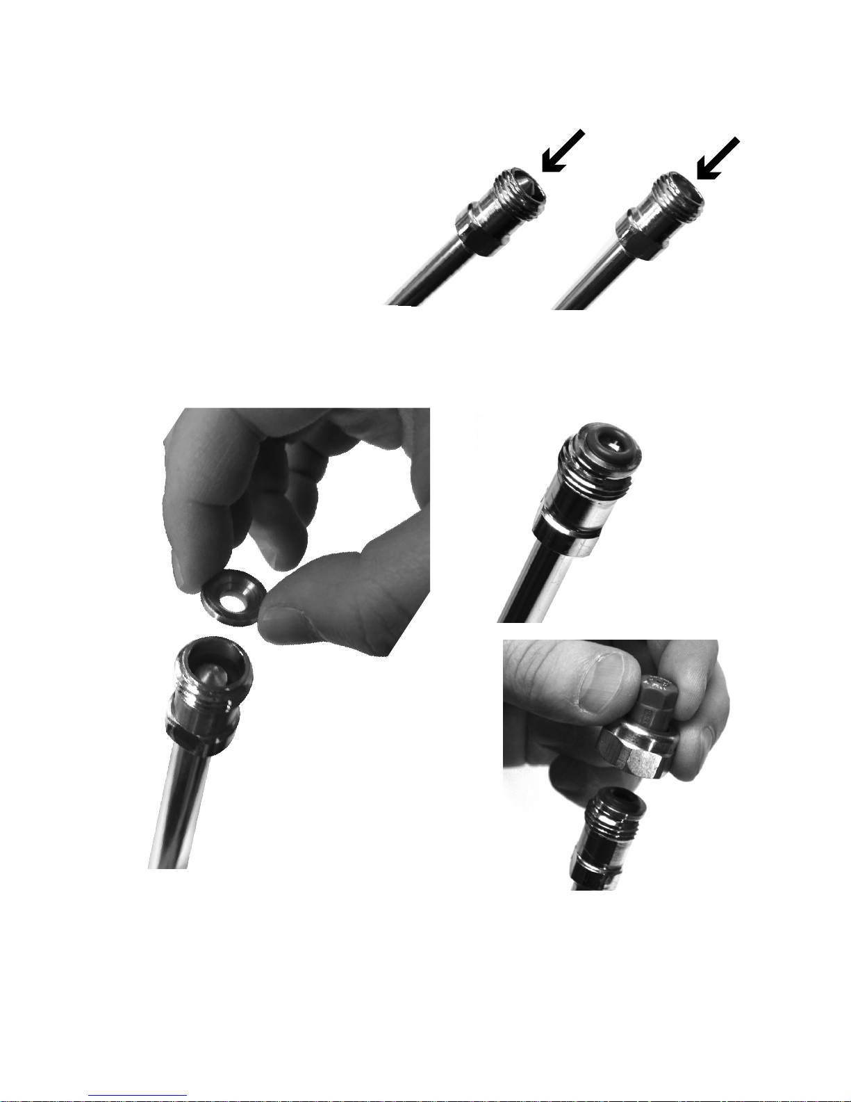
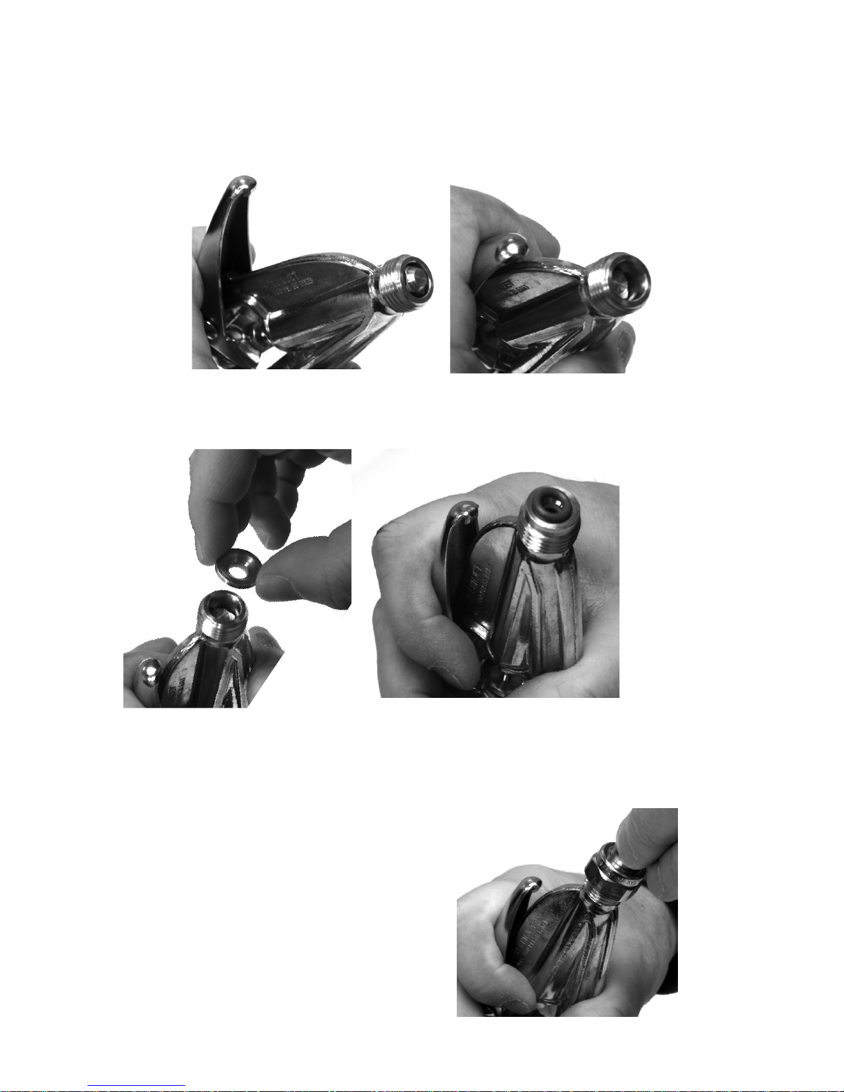
To assemble the tip to the extension,
draw back spray handle trigger to
retract plunger at the extension end
(as shown in gures 21 & 22). Hold in
place until the tip is securely fastened.
Set Teon shuto at extension opening, while keeping the plunger retracted (as
shown in gure 23).
Rest the o-ring on the Teon shuto, while keeping plunger drawn back (as
shown in gure 24)
Lastly, thread on the tip securely (as shown in gure 25), and work the spray
trigger 2-3 times before nally releasing it. Tighten the brass nut in the clockwise
direction using a 13/16” wrench.
Pg. 10
PS30 Tip Assembly
g. 21
g. 22
g. 23
g. 24
g. 25
Page 12
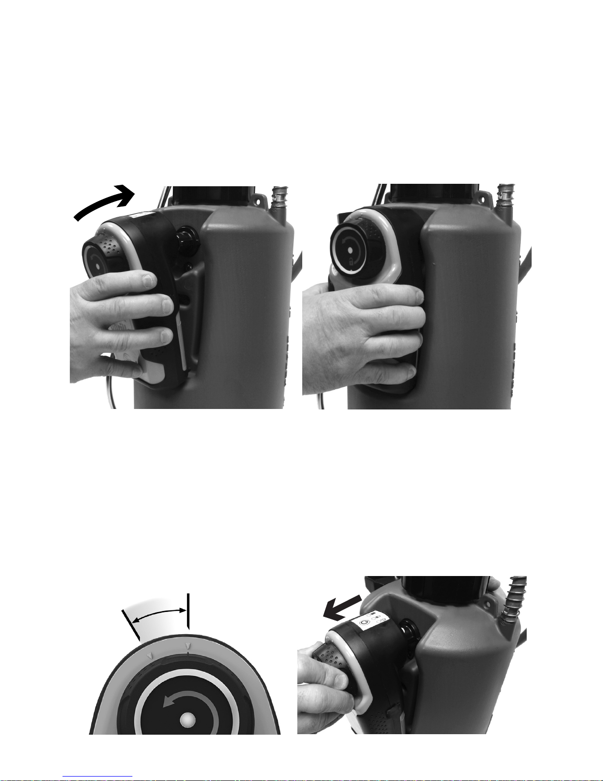
Rest the bottom of the PowerPack on the bottom of the tank’s PowerPack mounting recess (as shown above in gure 26) and tilt upwards into the pocket and
engage the quick connect tting (as shown below in gure 27), until a positive
click is heard. PowerPack is now ready for use.
Pg. 11
PowerPack Operation
g. 26 g. 27
PowerPack Removal
PowerPack Attachment
30°
g. 28
g. 29
The PowerPack MUST be removed correctly or damage may occur. To remove the
PowerPack from the tank, rotate the release knob in the COUNTERCLOCKWISE
direction until the knob indicator is in-line with the arrow on the housing (gure 3).
Pull the PowerPack away from the tank to fully remove (gure 29).
DO NOT attempt to pull the PowerPack o without rst rotating the knob.
Note: the knob is spring loaded, and will automatically reset when released.
Page 13
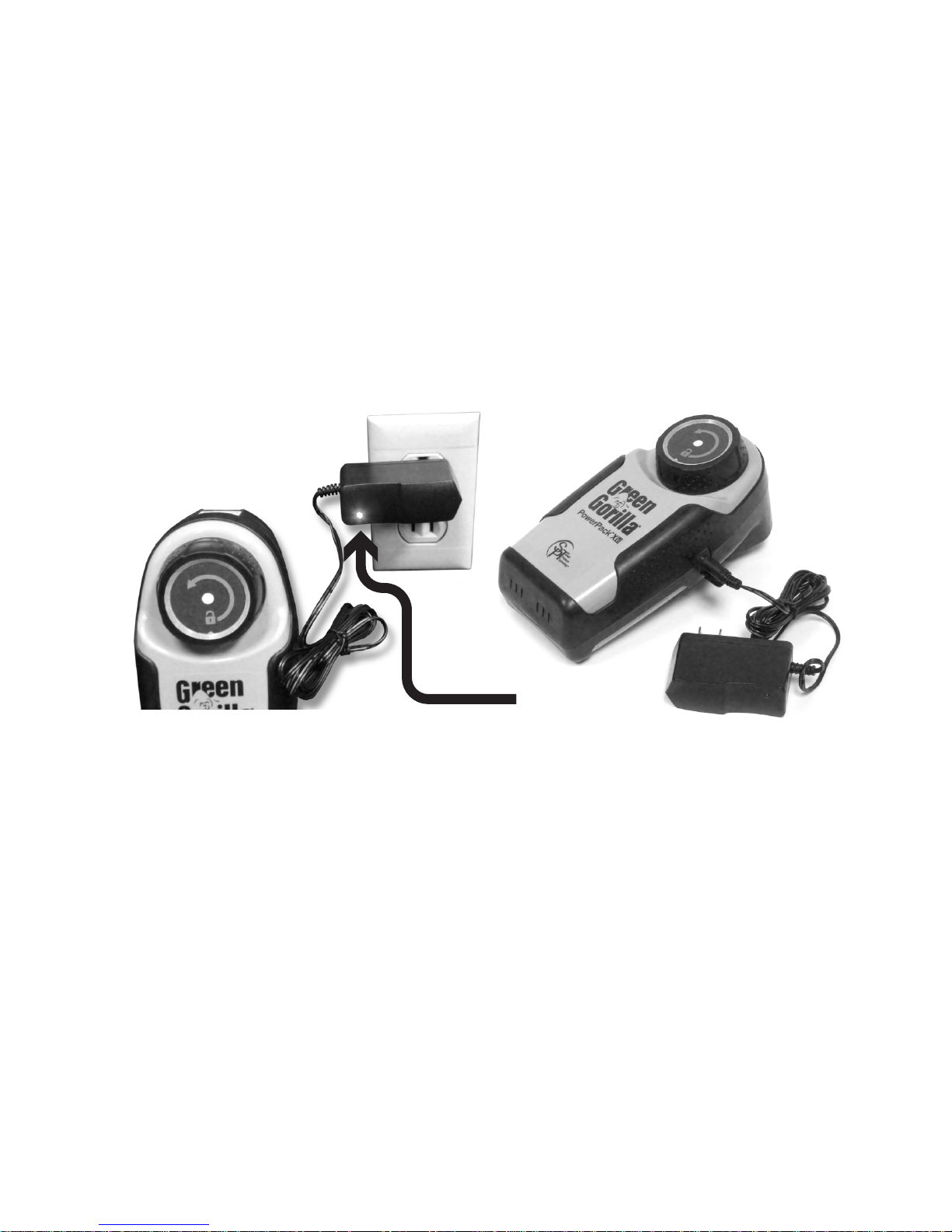
PowerPack Charging
Pg. 12
1. Insert the Green Gorilla standard wall charger into a 110 Vac wall outlet.
2. Locate the charging port cover on your PowerPack X. The charging port cover is
located on the right side of the PowerPack as shown in Figure 31.
3. The charging port is protected by a ip open cover. Gently pull up on the tab to
expose the charging port.
4. Firmly insert the wall charger plug into the port.
5. The wall charger indicator light will turn green when the lithium ion cells are fully
charged. Charge time is approximately 3-5 hrs.
6. After fully charging, remove the charger plug from the PowerPack charging port
and push the protective cover back into place.
7. Ensure that the PowerPack X battery level indicator shows green when the unit is
turned on.
IMPORTANT! If the PowerPack fails to turn on after charging, pull back the
protective cover and gently reinsert. A built-in safety interlock system that
prevents usage while charging may have become engaged due to over- insertion
of the protective cover.
g. 31
g. 30
This unit is equipped with the latest in lithium ion power technology. Ensure that
you are only using the Green Gorilla 110Vac charger that came with this unit. The
charger has been matched to the solid state electronics within the PowerPack itself
to ensure safe and reliable charging.
IMPORTANT! A safety interlock system incorporated into this system will not allow
the PowerPack to operate when the charger plug is engaged.
The wall charger is equipped with an indicator light that indicates when your system
is fully charged. The indicator light (as shown in Figure 30) is red during charging
periods and turns green when the lithium ion cells are fully charged. The following
steps should be used when charging your PowerPack.
Indicator
Light
Page 14
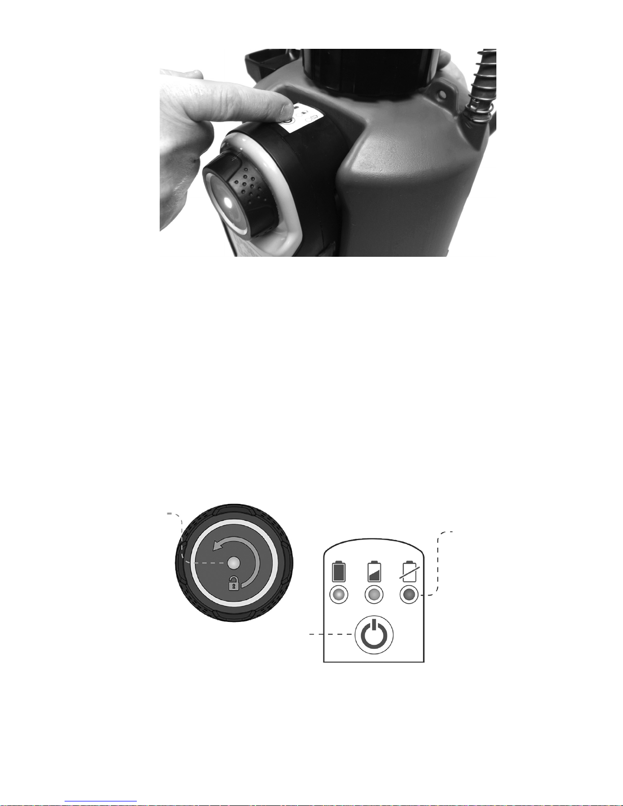
PowerPack Usage
Turn PowerPack on by depressing the on/o power button on the top surface of the
PowerPack as shown above (gure 32).
If fully charged, a green light will display on both the top surface and the center of the
knob. Both the knob indicator light and the power level indicator are synchronized to
indicate power depletion during normal operation. Green = Full Charged, Yellow = Half
Charge, Red = Low Battery (gures 33 & 34).
During normal operation, the PowerPack will automatically cycle to maintain the
factory pressure set point as necessary. The Power Level Indicator Lights will remain on
to indicate the PowerPack is in pressure sensing mode.
IMPORTANT! After lling and pressurizing the system purge air from the wand and
wand hose by spraying product into a container until no air or air bursts are detected.
Inadequate purging of the system may initially result in uneven spray pattern or a
longer than expected ow after the wand trigger has been released.
Pg. 13
Power Level
Indicator
Power Level
Indicator
On / O
g. 32
g. 33
g. 34
Page 15
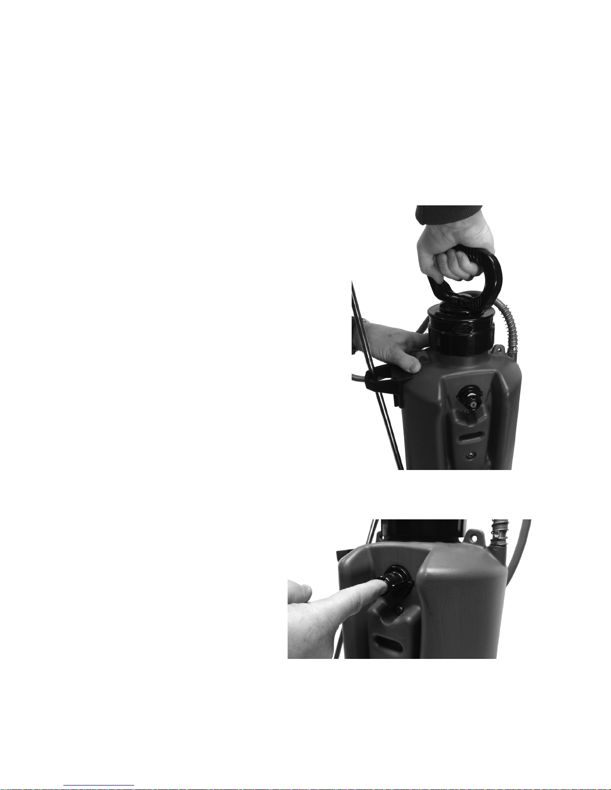
Tank Operation
Filling
Prior to rst use, it is highly recommended that an initial rinsing of the tank be
preformed. This is to ensure that any debris resulting from manufacturing has
been removed prior to running liquid through the wand. This will minimize
clogging of the strainer or wand tip and ensure proper wand operation.
Pg. 14
Seat the pressure relief valve by
depressing the red pin on the Quick
Connect Adaptor 2-3 times as
shown in gure 36. Completion of
this step is to ensure seating of the
internal seals.
Attach PowerPack (see page 11,
PowerPack Attachment).
Prior to lling, disconnect the PowerPack, to
reduce solution spills onto the unit (see page
11, PowerPack Removal).
Mix your solution as directed by the manufacturer’s instructions, and ll tank to desired
level (careful not exceed the maximum
working volume of your tank).
Assemble the manual pump and handle onto
the top of the tank by engaging threads and
rotate clockwise until the o-ring seal [underside of cap] is fully seated (gure 35).
Lock handle in place by rotating the pump
handle 90 degrees clockwise until a positive
click is felt.
IMPORTANT! Do not carry the tank by the
handle until the handle is in the locked
position. Damage may occur.
g. 35
g. 36
Page 16
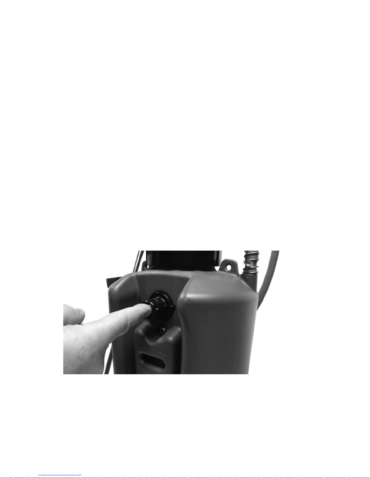
Pressure Relief System
The Green Gorilla ProLine sprayer is equipped with a patented Quick Connect
Adaptor, see gure 2. In addition to the quick connect functionality, the Quick
Connect Adaptor serves as both a manual and automatic pressure relief system.
During operation of the system, if the pressure in the tank exceeds the system
design pressure the pressure relief valve will automatically open and depressurize the system to the system design pressure. The pressure relief valve will reset
automatically when the tank pressure is returned to the system design pressure.
This functionality works with or without a PowerPack attached to the Quick
Connect Adaptor. This is a safety feature of the Green Gorilla system and should
not be altered or disabled.
At any time, you may manually release the tank's pressure by depressing the red
pin in the center of the Quick Connect Adaptor. (gure 37) Always keep your
face clear of the Quick Connect Adaptor when releasing pressure and wear
protection as recommended by the chemical manufacturer.
IMPORTANT! Prior to removing the manual pump cap, release the pressure
manually at the Quick Connect Adaptor (depress red pin). Releasing pressure by
this method allows for easier removal of the manual pump cap.
Pg. 15
g. 37
Page 17

Cleaning and Maintenance
1. If tank is pressurized, RELEASE AIR PRESSURE by depressing the red pin in the
Quick Connect Adaptor. (gure 37) Push red pin in rmly and hold to allow all
pressure to escape.
2. Loosen manual pump slowly (gure 35) and remove by rotating in the
counter-clockwise direction. (You may need to push down on the handle
slightly to unlock it.) Properly store any remaining spray solution per the
manufacturer’s recommendation. Triple rinse all parts thoroughly with clean
water.
3. To ush the hose and wand, leave a small amount of clean water in tank,
pressurize and ush by depressing spray handle trigger for approximately 30
seconds. Release the pressure as outlined in step 1.
4. Drain the wand handle, extension, and hose by holding the wand handle
above the tank and depressing the trigger. This will allow all trapped water to
drain back into the depressurized tank.
5. Clean the spray wand's nozzle orices using a small cleaning brush set.
6. Always store tank indoors and empty and with the manual pump loose. If the
tank is to be stored outdoors, during freezing temperatures, the tank and
wand should be ushed with RV/Marine Anti-freeze to prevent equipment
damage.
7. If Quick Connect Adaptor pressure relief valve (gure 37) is dirty, clean with
fresh water.
IMPORTANT! Do no store tank under pressure for extended periods.
Pg. 16
Page 18
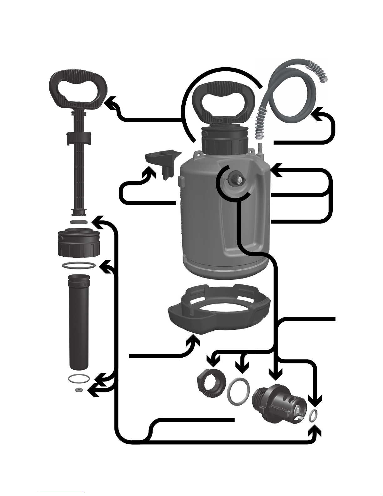
48” Hose
1.5 Tank w/ Connector
Easy-Twist
Quick-Connect
(full assembly)
Manual Pump
(full assembly)
Wand Holder
Tank Base w/ Drip Cup
Tank (w/Pump & Connector)
Seal Kit
2.5 Tank w/ Connector
Tank Replacement Parts
Pg. 17
g. 38
P-08-XX-00166
P-08-PL-00156
P-08-PL-00504
P-08-PL-00151
P-08-PL-00152
P-08-PL-00155
P-08-PL-00179
P-08-PL-00224
Page 19
Pg. 18
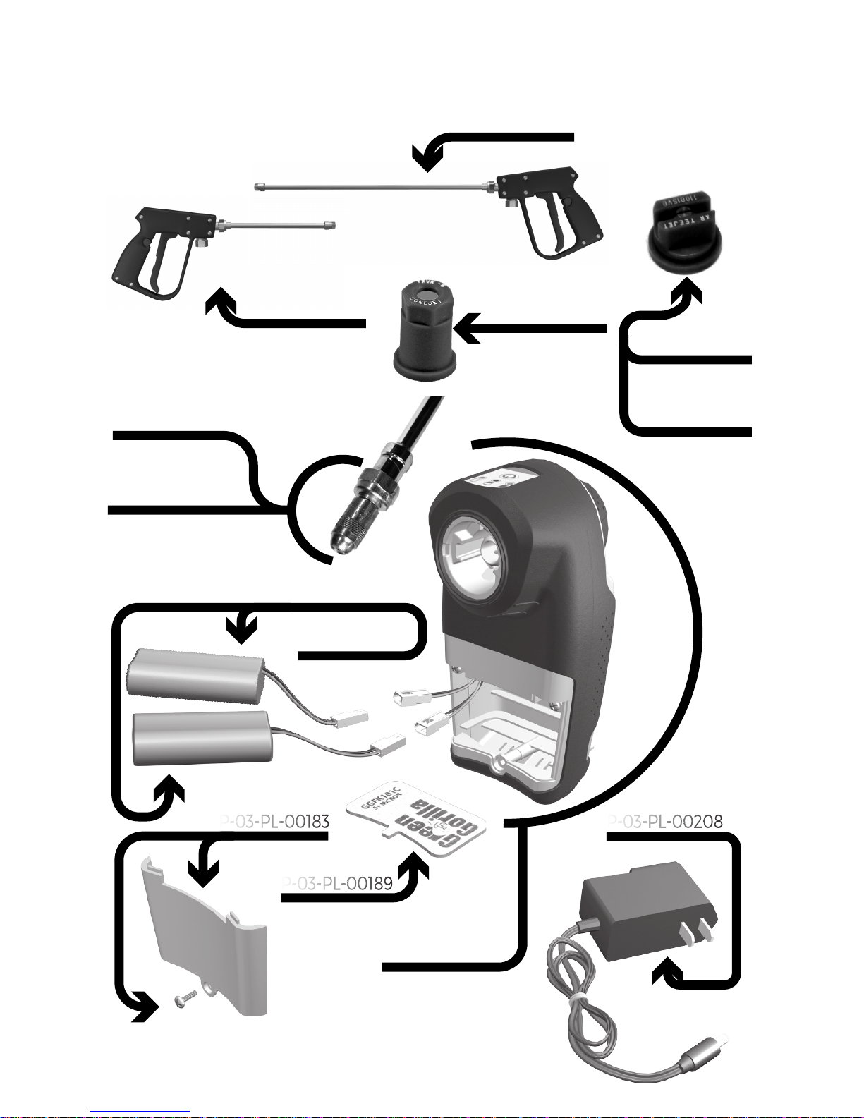
PowerPack Replacement Parts
g. 39
PowerPack X Vi
(full assembly)
Air Filter
Battery
(set of two)
#8 ConeJet® Brass
#10 ConeJet® Brass
AA30 w/18” Ext.
AA30 w/8” Ext.
Battery Door
& Screw
Wall Charger
P-08-XX-00016
P-06-XX-00589
P-08-XX-00008
P-08-XX-00013
P-03-PL-00187
P-03-PL-00189
P-03-PL-00208
P-08-PL-00204
P-03-PL-00183
P-08-XX-00136
#1 Fan Tip
w/brass nut
#6 ConeJet®
w/brass nut
P-08-PL-00630
P-08-XX-00137
#15 Fan Tip
w/brass nut
Page 20

ForeFront Product Design LLC warrants its ProLine™ Spray System
for a period of one year from the date of original purchase. We
will repair or replace at our option, any part or parts of the product and accessories covered under this warranty which examination proves to be defective in workmanship or material during the
warranty period.
For repair or replacement return the complete system or accessory, transportation prepaid, to ForeFront Product Design LLC, 568
Braddock Ave, East Pittsburgh, PA 15112, USA, or to an alternate
address provided by customer support.
Proof of purchase may be required. This warranty does not apply
to repair or replacement required due to misuse, abuse, normal
wear and tear or repairs attempted or made by other than or
Service Center.
Under no circumstances will ForeFront Product Design LLC be
liable for incidental or consequential damages resulting from
defective products.
This warranty is ForeFront Product Design's sole warranty and sets
forth the customer's exclusive remedy, with respect to defective
products; all other warranties, expressed or implied, whether of
merchantability, tness for purpose, or otherwise, are expressly
disclaimed by ForeFront Product Design, LLC.
ForeFront Product Design, LLC
PO Box 18273
Pittsburgh, PA 15236
Customer Service
+1 800 866 2122
www.green-gorilla.com
LIMITED WARRANTY
(USA & Canada Only)
Pg. 19
 Loading...