

Green Gorilla GG015B, GG025B Owner's Manual
CLEANING AND MAINTENANCE INSTRUCTIONS
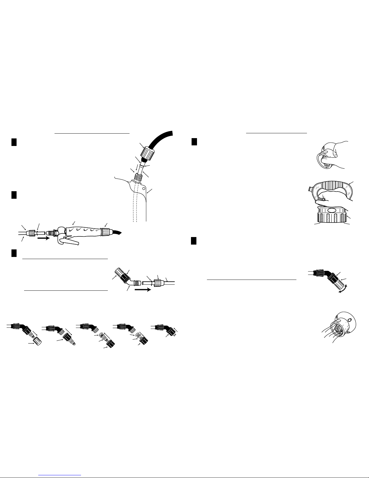
RELEASE AIR PRESSURE by depressing the red pin in the Easy-Twist Quick-Connect™. (Figure 4a) Push in firmly and
hold to allow all pressure to escape.
Loosen manual pump slowly (Figure 4b) and remove. (You may need to push down on the handle slightly to unlock it.)
Properly dispose of or store any remaining spray solution. Rinse all parts thoroughly with clean water.
Leaving a small amount of clean water in tank, pressurize and flush the equipment by depressing spray handle trigger
approximately 30 seconds.
RELEASE REMAINING PRESSURE by depressing the red pin in the Easy-Twist Quick-Connect™. (Figure 4a) Push in
firmly and hold to allow all pressure to escape; remove manual pump. (Figure 4b) Rinse tank again and empty water.
Clean the spray wand's nozzle cap orifice using a small object, like a toothpick.
Always store tank empty and with the manual pump loose.
If spray wand trigger is sluggish, flip the trigger to the open-locked position and apply several drops of oil into trigger base.
If pressure relief valve and Easy-Twist Quick-Connect™ (Figure 5b) are dirty, flush with fresh water.
WARNING: If, at anytime, you find that the Easy-Twist Quick-Connect™ and pressure relief valve, OR the manual pump
assembly has suffered damage, discontinue use immediately and contact our customer service. Garden sprayers can be
dangerous if improperly maintained or damaged.
The Green Gorilla
®
Advanced Spray Systems, Premium Sprayer is built to give years of trouble free service. A small amount
of care will repay you in long life and efficient operation.
LIMITED WARRANTY
(USA and Canada only)
ForeFront Product Design, LLC.
P.O. Box 18273
Pittsburgh, PA 15236
Customer Service
1-800-866-2122
ForeFront Product Design LLC warrants to the original consumer purchaser of this product at retail that it is free from
problems in materials and workmanship for the period of 2 years from the original date of purchase. This warranty does not
apply to damage to the product resulting from accident, misuse, neglect, alteration, modification, tampering, or failure to
follow instructions supplied with the product. This warranty does not cover normal wear and tear of o-rings or seals.
If the product or any part of it should malfunction with the warranty period, telephone our CONSUMER HELP LINE at
1-800-866-2122 for fast service.
We will, at our discretion, repair or replace any problem parts free of charge. We retain the option of requiring the prepaid
return of the product, along with original proof of purchase, to ForeFront Product Design LLC, P.O Box 18273, Pittsburgh
PA 15236, USA, or to an alternate address provided by customer support.
This warranty applies in the United States and Canada. You must retain your original sales receipt as proof of the date of
purchase and include the original or a copy with any product returns. ANY IMPLIED WARRANTIES, INCLUDING ANY
IMPLIED WARRANTY OF MERCHANTABILITY OR FITNESS FOR CONSUMER USE, ARE LIMITED TO 2
YEARS. FOREFRONT PRODUCT DESIGN LLC EXCLUDES LIABILITY UNDER THIS WARRANTY FOR ANY
AND ALL INCIDENTAL AND CONSEQUENTIAL LOSS OR DAMAGES.
Some states do not allow limitations on how long an implied warranty lasts or the exclusion or limitation of incidental or
consequential loss or damages, so these limitation or exclusions may not apply to you. This warranty gives you specific legal
rights, and you may also have other rights that vary from state to state.
OWNER’S GUIDE
#GG015B, #GG025B
Green Gorilla
®
Premium Sprayer
NON-CORROSIVE, POLYETHYLENE,
SPRAY TANK
PLEASE READ AND FOLLOW ALL INSTRUCTIONS BEFORE USING SPRAYER
WARNING
FAILURE TO HEED ALL SAFETY INSTRUCTIONS AND WARNINGS COULD RESULT IN SERIOUS BODILY INJURY.
DO NOT USE ANY FLAMMABLES IN THIS SPRAYER, this could cause the sprayer to explode and cause SERIOUS INJURY.
DO NOT USE ANY CAUSTICS OR ACIDS IN THIS SPRAYER, this could weaken the sprayer parts and cause SERIOUS INJURY.
Always inspect your sprayer and accessories thoroughly before each use.
Be sure hose is securely attached and in good condition before pressurizing tank.
Always tighten the manual pump assembly securely by hand. An improperly tightened manual pump could be forcibly ejected and cause
serious injury.
Always test with water at beginning of each season.
Always follow directions on spray material containers and accessories. Read them thoroughly and follow them carefully.
DO NOT pressurize the tank with anything other than a recommended Green Gorilla® manual pump or Green Gorilla® accessory.
DO NOT use solutions hotter than 105oF.
DO NOT damage, plug or alter the function of the Easy-Twist Quick-Connect™ & pressure relief valve; this could cause sprayer to explode.
DO NOT pressurize sprayer until ready to use. Do not leave pressurized sprayer unattended.
DO NOT lift or carry sprayer by the hose or spray wand.
Clean tank and pressure relief valve thoroughly with soap and water after herbicides or other chemicals have been used.
Read and follow all instructions for this sprayer before use.
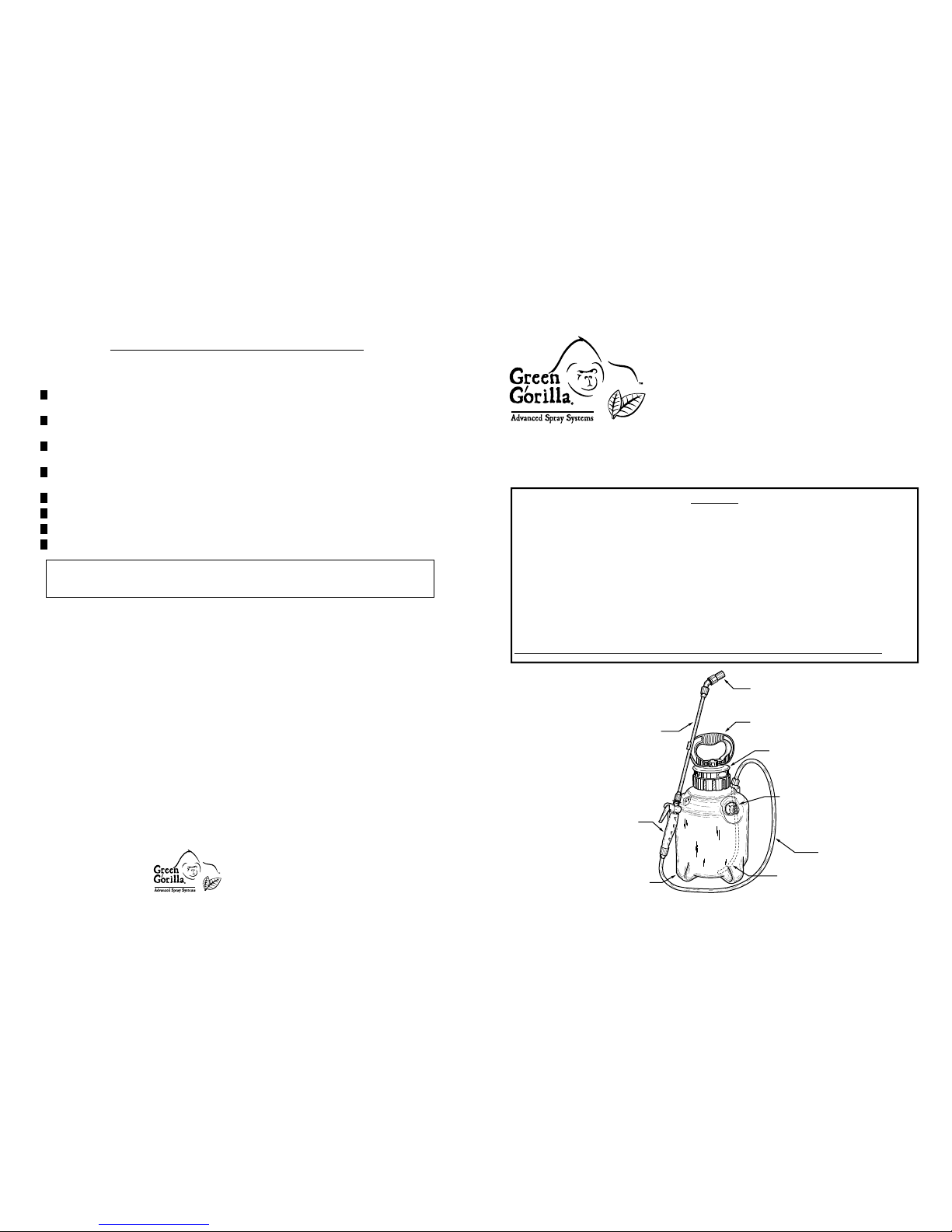
Green Gorilla® Advanced Spray System
Premium Sprayer Overview
©2013 ForeFront Product Design LLC. All rights reserved.
Wand
Handle
Manual Pump
Handle
Manual Pump
Assembly
Spray Wand
Spray Nozzle
Supply Tube
Spray Hose
Tank Body
Easy-Twist Quick-Connect™
& Pressure Relief Valve
Thank you for purchasing the Green Gorilla
®
Advanced Spray Systems, Premium Sprayer. With a small amount of care this
spray system will repay you with efficient operation and last for many spray seasons. The instructions and maintenance tips
provided in this owner’s guide are to assist you in the care of your Green Gorilla® Premium Sprayer. Be sure to read all warnings
and follow all instructions before using the sprayer.
1
2
3
4
5
6
7
8
5
Figure 5a
Nozzle
Cap
Nozzle
Nut
5a. Manually pressurize the tank by pumping until desired pressure is reached. Then, push the pump handle down
completely into the slots in the pump base and rotate the handle to the locked position (as indicated on the base). To
unlock the handle for further pumping or to remove the cap, press down slightly on the handle and rotate (as indicated
on the base).
(If optional Power Pack accessory is being used, refer to pressurization directions included with the Power Pack.)
NOTE: For proper operation, ensure that debris DOES NOT enter the
opening where the pump handle meets the pump base.
5b. Ensure that black nozzle nut is fully tightened, before adjusting nozzle cap.
Tighten cap for a fine mist spray or loosen for a coarser spray or a solid stream. (Figure 5a)
WARNING: Once a solid stream is reached, DO NOT continue loosening any further. Loosening cap
too far will result in the cap falling off, allowing spray material to spray back at you.
Pressurizing and Spraying
Figure 5b
The Green Gorilla® Premium Sprayer is equipped with a built in pressure relief valve
(Figure 5b). The pressure relief valve is part of the Easy-Twist Quick-Connect™ system
and will prevent the tank from becoming over pressurized. The pressure relief valve will
function with or without accessories attached to the tank.
If a hissing sound is detected through the pressure relief valve, the sprayer is over
pressurized. The pressure relief will reset automatically when the tank pressure is returned
to safe operating limits. The tank may become over pressurized by manually over pumping
or by increased pressure due to heating of the tank contents from environmental conditions.
NOTE: For proper operation keep pressure relief valve clean of dirt and debris.
At any time, you may manually release the tank's pressure by depressing the red pin in the
center of the Easy-Twist Quick-Connect™ valve. (Figure 4a) Always keep your face clear
of the Easy-Twist Quick-Connect™ and pressure relief valve when releasing pressure.
Pressure Relief System
4
Figure 4a
Filling Your Sprayer
4a. Before every filling, first depress the manual pressure relief valve on the Easy-Twist
Quick-Connect™ by placing your thumb on the red pin, fully covering the opening in
the center of the pin. (Figure 4a) Depress it firmly and hold to manually release any
pressure and then repeat several times to clear any debris and to ensure the pressure
relief valve is functioning properly.
DO NOT have your face near the Easy-Twist Quick-Connect™ valve whenever
releasing pressure, as debris could be blown back at you.
4b. Loosen the manual pump assembly by grasping the bottom of the handle. (Figure 4b)
Once loosened, fully unscrew the manual pump assembly by the pump handle or
pump base. (You may need to press down slightly on the handle to unlock it.)
4c. Mix spray solution in separate receptacle, following manufacturers' directions
for the spray solutions.
4d. Strain solution through fine cheesecloth or household strainer to remove particles
that could clog nozzle. Use any amount of liquid up to the tank's maximum capacity
(1½ gallons or 2½ gallons depending on sprayer model). DO NOT over-fill.
4e. Replace manual pump assembly and screw it back down by the base or handle till
you feel resistance. Finish tightening the pump assembly by grasping the base of the
handle, as pictured in Figure 4b, to ensure it is snug and has made a good seal.
Ensure that the pump handle is in the locked position before carrying.
NOTE: Sprayer should only be carried by the manual pump handle (when in locked position) or with approved
accessories. Never carry tank by the hose, spray wand, or unlocked pump handle.
Figure 4b
Pump
Handle
Pump
Base
HOW TO USE YOUR SPRAYER
(Skip this step if nozzle is already attached to the end of the spray wand.)
Firstly, ensure that black nozzle nut is fully tightened to nozzle elbow.
3b. Unscrew red nozzle cap fully to remove and set aside. (Figure 3b)
3c. Unscrew black nozzle nut. (Figure 3c)
3d. Remove the yellow filter and red spray tip and set aside. (Figure 3d)
3e. Insert fan tip into nozzle nut, followed by the filter. (Figure 3e)
Caution: Be careful to replace the filter in the direction pictured.
3f. Hand tighten the nozzle nut back onto the wand (Figure 3f).
Figure 3b
Nozzle
Cap
Figure 3f
Nozzle
Nut
Figure 3e
Fan
Tip
Nozzle
Nut
Filter
Figure 3d
Filter
Spray
Tip
Nozzle
Nut
Figure 3c
Nozzle
Nut
Attach Spray Nozzle
Optional: Install Spray Wand Fan Tip
3a. Attach spray nozzle to spray wand by inserting wand into open end
of spray nozzle. Tighten the wand nut securely by hand. (Figure 3a)
NOTE: Never use tools to tighten connection nuts.
3
Figure 3a
Nozzle
Elbow
Nozzle
Cap
Spray
Wand
Wand
Nut
O-Ring
Nozzle
Nut
Attach spray wand to wand handle by inserting wand into open end of handle.
Tighten the wand nut securely by hand.
NOTE: Never use tools to tighten connection nuts. DO NOT over tighten
Wand & Wand Handle Nuts. Small gaps between the nuts and the handle are
normal.
Figure 2
Wand
Nut
O-Ring
Wand Handle
Spray
Wand
Wand Handle
Nut
Attach Spray Wand to Wand Handle Assembly
2
HOW TO ASSEMBLE YOUR SPRAYER
Attach Spray Hose and Wand Handle Assembly to the Tank
1a. Feed the supply tube into the threaded hose port on the tank, until the o-ring
has engaged the inside of the hose port. (If necessary, apply a small amount
of liquid soap or petroleum jelly to the o-ring to aid in assembly.)
NOTE: Ensure that the o-ring does not roll up as you engage the hose port. If it
does, remove it and press back in. This should let the o-ring slide back into the
groove in the supply tube holder.
1b. Hand tighten the hose nut onto threaded hose port until snug.
NOTE: Never use tools to tighten connection nuts.
1
Figure 1
Hose
Port
Supply
Tube
Holder
Hose
Nut
Supply
Tube
Spray
Tank
O-Ring
(apply liquid soap
or petroleum jelly
to aid assembly)
(Skip this step if hose is already attached to the spray tank.)
 Loading...