

Page 1
RDX Quick Start Guide
Page 2

Green-GO RDX
Quick Start Guide
Product description
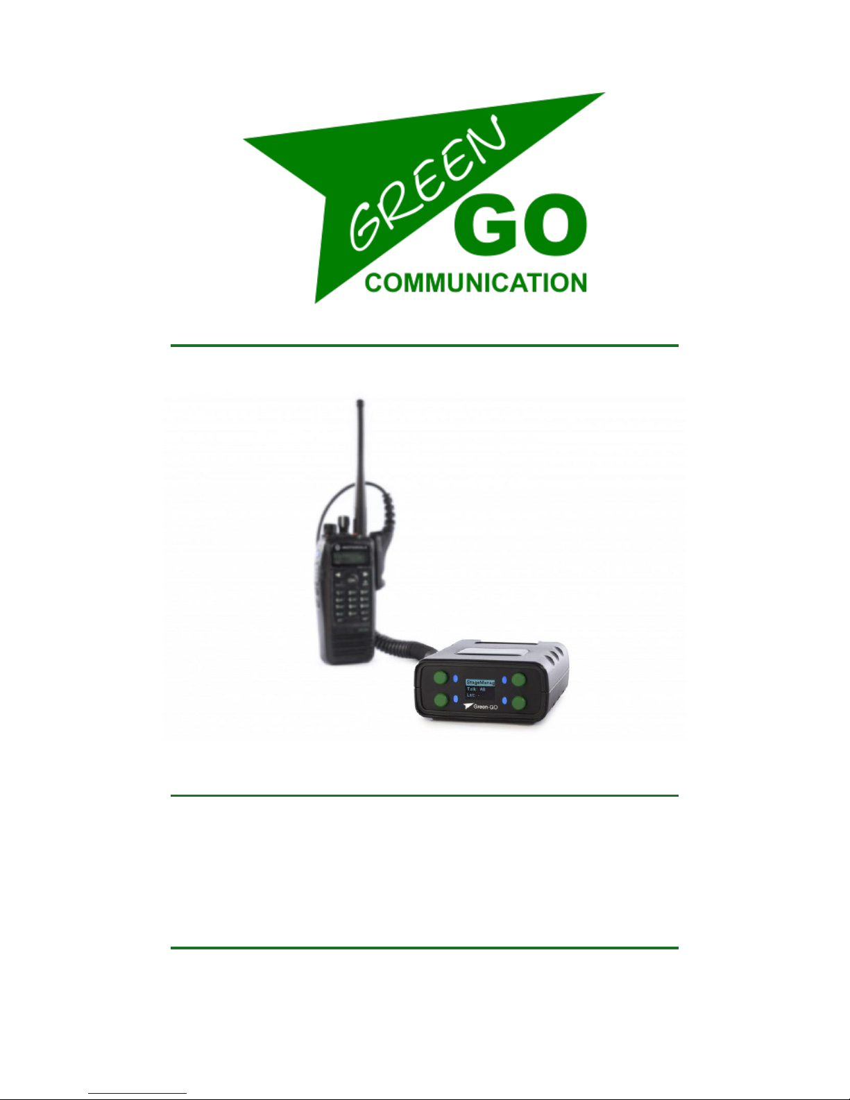
With the Green-GO Radio Interface you can connect your radio to the Green-GO
network through a D-SUB 9 connector.
Features
• Connect your (Walkie-Talkie) radio to the Green-GO network
• Push-To-Talk function to remotely operate the (Walkie-Talkie) radio
• One radio channel becomes one group of the Green-GO network
• Powered by PoE (802.3af-2003 standard) from Ethernet port
Page 3

Setup menu navigation
Pressing the two buttons on the left-hand side of the screen simultaneously will open
the RDX setup menu. Once in the menu, the button on the top left will act as the
selection and confirmation button. The button on the bottom left will take you one
step back out of the currently selected option or menu.
Using the two buttons on the right-hand side, you can scroll through the menu.
Having selected an editable parameter, these buttons will let you either raise or
lower the parameter’s value.
Setup menu overview
The setup menu offers a range of different settings to modify your RDX.
The menu sections and their supplementary options are described in detail below.
Modifying the program audio parameters
Program In
Src Select the program audio source.
This will open up a list of sources that can be selected as the program audio
source (Stage, Sound, Light, Video, etc.).
Vol Set the volume of the program audio. The range of the volume can be altered
between 12dB and -36dB. To mute the program audio, scroll past -36dB and
the MUTE value will show up.
Dim Dim the program audio during communication. Dimming range can be altered
from 0dB to -12dB to -24dB, and a mute option when you scroll past -24dB.
Assigning groups and users to channels
Channel Assignment
1-32 Select one of the 32 available channel to assign a user or group to.
ID ID of the user or group assigned to the channel
Group Assign a group to the channel
User Assign a user to the channel
None Remove assigned group/user from the channel
Page 4

Set Label Set a different label for the channel
Group Select a group label
User Select a user label
Clear Clear the label set
Talk Set the way the Talk button acts when pressed
Latch / Momentary Short press: Latch / Long press: Momentary
Latch Pressing the Talk button enables talking, pressing again
disables talking
Momentary Talk button must be kept pressed to enable talking
Disabled Disable talking for this channel
Listen On / Listen Off
Listen On Enable listening to this channel
Listen Off Display will still indicate talking, but audio will be off
Volume Set the volume for this channel. The range of the volume can be
altered between 12dB and -36dB. To mute the program audio, scroll past 36dB and the MUTE value will show up.
High Priority / Normal Priority / Low Priority Set the priority level of the
channel - see also Priority dim in the Options menu
Call Send Enabled / Disabled Enables or disables the ability to send calls
from the channel
Call Receive Enabled / Disabled Enables or disables the ability to receive
calls on the channel
Enhanced / Normal Bandwidth Set the bandwidth of the channel
An Assign group to be handled as Announce Channel
Em Assign group to be handled as Emergency Channel
AutoTalk
Ch1-32 / Off
Page 5

Modifying the audio settings
Audio Settings
Volume Set the volume for the RDX. The volume range can be altered between
-10dB and -60dB.
AutoGain Set the dynamic amplification to avoid distortion.
Available settings are Slow – Med – Fast – Off. If AutoGain is turned off the Max Gain
option is disabled.
MaxG Set the maximum gain of the input signal - editable range is 30 – 70dB.
Thld Set the threshold level required for the input signal to be transmitted –
editable range is -40 to -20dB.
General options
Options
Active Time Set the time for a channel to be active after the last audio activity.
Editable range is 0.5 – 45.0 seconds.
Isolate On/Off Determines whether or not all other channels will be muted when
you enable Talk on a channel
Buzzer On/Off Enable/disable the buzzer that will sound when an alert is received
Tone Set the level of the audio signal used for Alert, Cue, Connection Status and
Battery status – range is MAX, -1dB to -48dB, MUTE
No Listen on Talk / Listen on Talk Determines whether or not a muted channel is
allowed to be temporarily unmuted when enabling Talk on the channel
Answer Enabled / No Answer Enable or disable the ability to answer a call
Popup Select the popup behavior
Popup All All popups are shown
Popup Cue + Direct Popups for Cue signals and direct Talk only
Popup Cue Popups for Cue signals only
No Popup No popups
Priority Dim Set the dimming level of a lower priority channel if a higher priority
channel becomes active / Range: 0dB -24db, MUTE
Direct Priority Set the priority for direct channels: Low / Normal / High
Direct Volume Set the volume for direct channels / Range: 12db -36dB, MUTE
AutoTalk Ch1-32 / Off
Page 6

User selection
Set User Selection of the designated user of the RDX device
StageManager
FOH
Monitor
Director
etc.
Configuration cloning
Clone Config Clone a configuration file from the network
Configuration File A Load configuration file A
Configuration File B Load configuration file B
etc.
Factory Default Load the factory default configuration file
Connection configuration
Connection Set the type of connection to be used
Local Connection Use local connection
Remote Connection Use remote connection
Password Set the password
Generate password Generate a new password
Remote Port Set the remote port to be used
Remote IP Set the remote IP to be used
Backup
OFF / 0.0.0.1
SndBuf
Default / Small / Normal / Large
RecvBuf
Auto / Small / Normal / Large
Save Save the current Remote Connection setup
Latency Connection Use latency connection
Audio
Normal / Compressed
FEC Set the Forward Error Correction type used
--- / On / Compressed
Latency
Save Save the current Latency Connection setup
Page 7

Network settings
Dynamic
ON Use a dynamic IP
OFF Use a static IP
IP address Set the IP address to be used
Netmask Set the netmask to be used
Gateway Set the gateway to be used
Save Save the current network setup
Device options
Device Options
Flip Selects parts of the display or the entire display to be turned upside down
Both Flip menu and main screen
Menu Flip only the setup menu
Main Flip only the main screen
Off Do not flip anything
Scr Saver Set the amount of time since the last activity before the display turns off
Range: Always On – 10 sec – 30 sec – 1 min – 10 min – 30 min – 1 hour – 2 hours
Scr bright Set the brightness of the RDX screen / Range: 0 – 15
LED bright Set the brightness of the LEDs / Range: Off – 1 – 2 – 3 – 4 – 5 - 6 – Max
Device information
Info Shows general information about the RDX
SN: xxx Serial number of the RDX
TD Radio 4a49 Firmware information
TD Radio 4a49 Firmware version
Aug 2 2017 Date of firmware build
17:18:57 Time of firmware build
IP: xxx.xxx.xxx.xx IP address of the RDX
Mac: xx:xx:xx:xx:xx:xx Mac address of the RDX
Reset All Settings Resets all IP, Audio, User and Channel settings.
Pairings are not affected and configuration file is not changed.
Page 8
Connecting a radio to the RDX
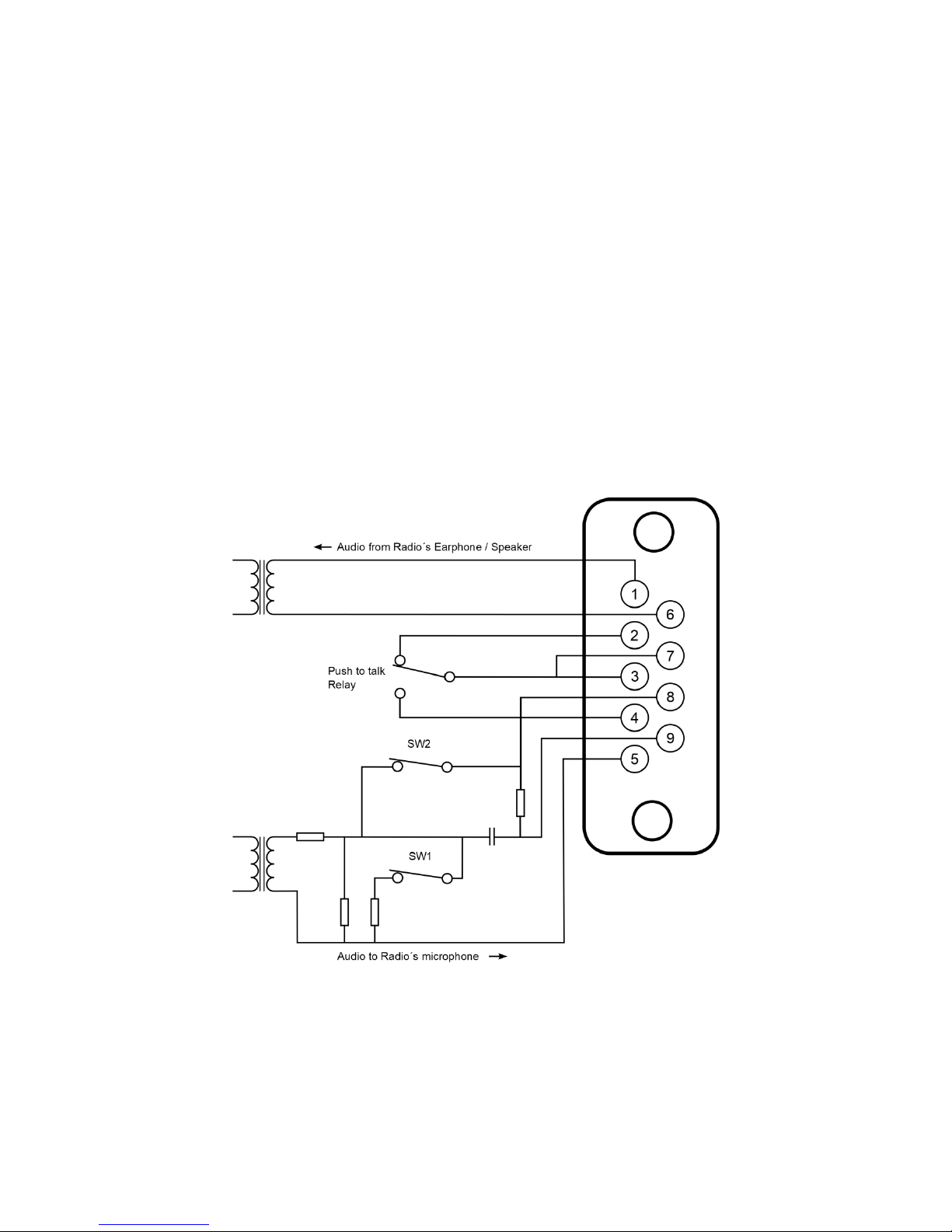
The Green-GO RDX can be connected to a broad range of two-way radios.
Using the diagrams below, you can create a connector cable for the radio type that
you wish to use. This cable needs to be connected to the D-SUB 9 pin connector
located on the back of the RDX.
The RDX is able to provide precise level matching to practically any two-way radio.
Upon detection of audio on the Green-GO network by the RDX, a Push-To-Talk relay
is activated that takes care of the keying of the radio. A suitable connector cable
(detailed below) - together with the relay contacts - makes sure that the transmitter
will be properly keyed to a radio.
The diagram below shows the D-SUB 9 connections for linking the Green-GO RDX to a
radio base station.
Page 9
Cable connections
A connector cable is required to connect a (Walkie-Talkie) radio to the RDX. This cable
should consist of single conductor shielded wire and should not be longer than 1.5 m
to prevent signal loss. The radio base station can be linked to the RDX by attaching
molded connectors (obtained from e.g. an external microphone or earphone) to the
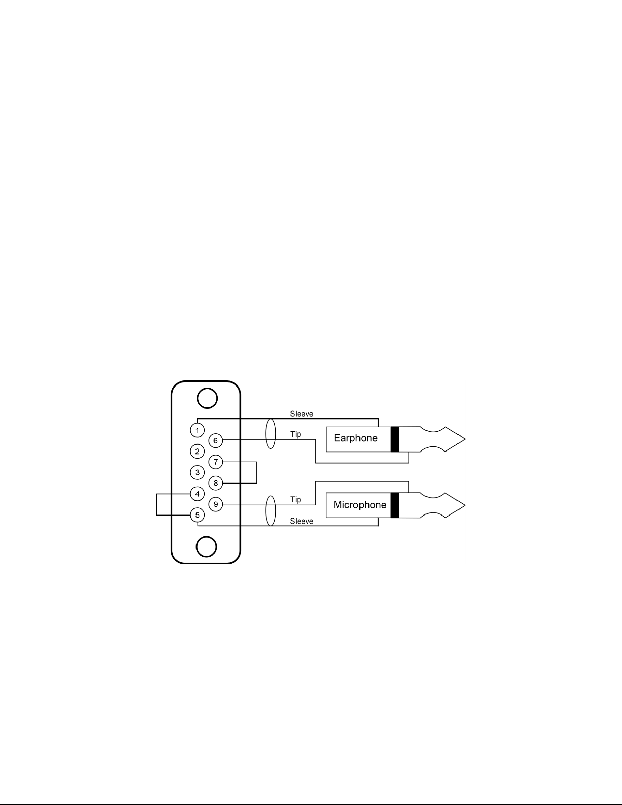
connector cable. The following diagram illustrates how the cable should be
connected to the D-SUB 9 pin connector.
After connecting the cable, the microphone type and level need to be set up. The
internal jumpers of the RDX can be configured - according to the three diagrams
pictured below - to accommodate specific microphone types.
Because each type of radio has a different way of keying the transmitter, it can be a
challenge to correctly key the specific radio you will be using. Knowing which type of
external microphone your radio uses helps to verify the correct jumper settings and
connector wiring. The diagrams below show the most commonly used setups.
Relay shunting the microphone
( e.g. Motorola Radius, GP300, SP-50, Sport 7X )
Jumper settings
SW2 off (DC path for microphone)
SW1 on (attenuator)
Page 10
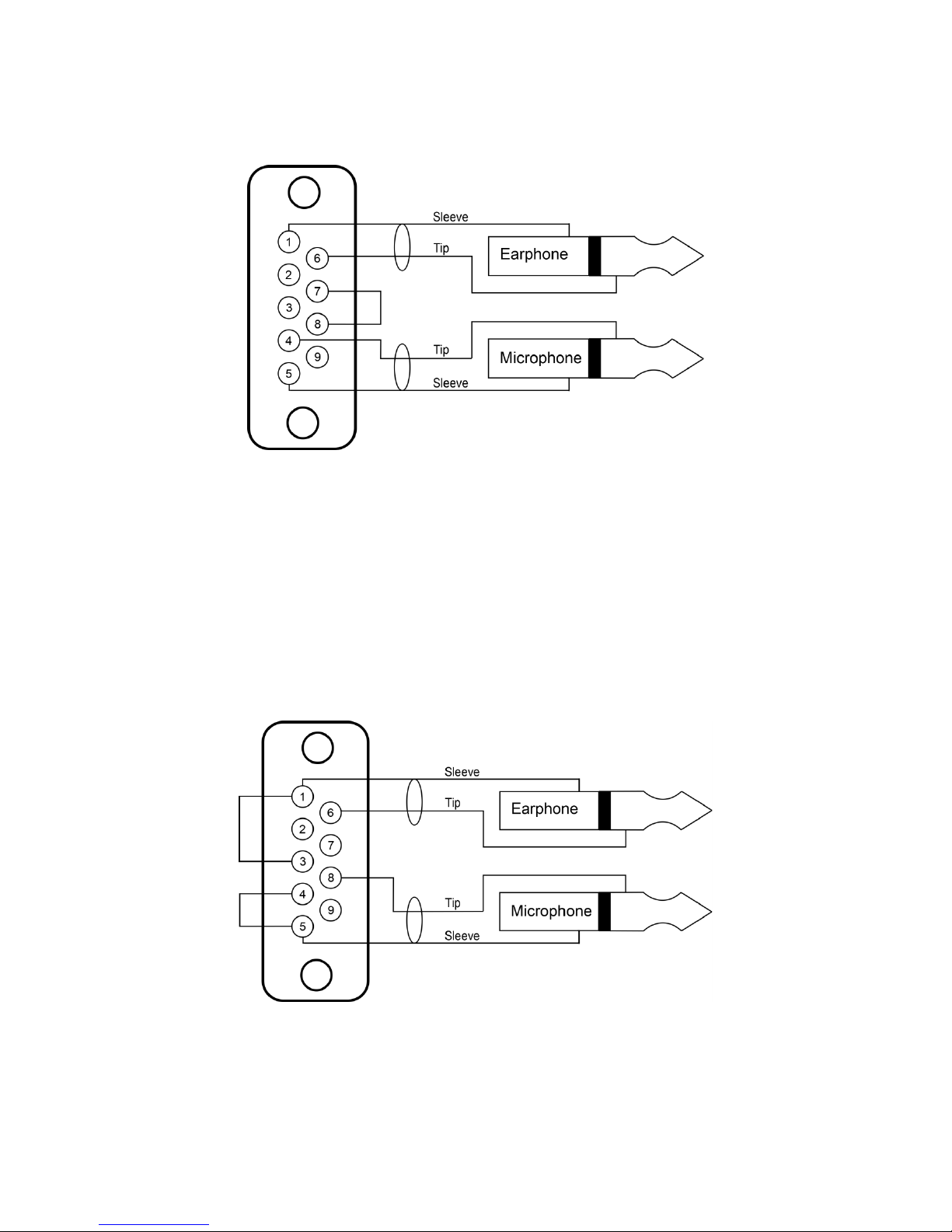
Relay in series with microphone
Jumper settings
SW2 on (DC path for microphone)
SW1 on (attenuator)
Relay across microphone sleeves & earphone connector sleeves
( e.g. Uniden SPH, Motorola Radius P-50 )
Jumper settings
SW2 on (DC path for microphone)
SW1 on (attenuator)
Page 11

General safety instructions
Read all instructions - especially the safety requirements - in the user manual before use.
- Keep these instructions - the safety and operating instructions should be retained for
future reference. - Carefully follow all instructions.
Cleaning
Disconnect all connected supply and signal cables before cleaning the unit. - Clean with a dry cloth. Do not use any liquid or spray on the unit.
Usage
Do not use the unit near water or moisture. - Do not block any ventilation openings, they are
necessary for the essential airflow within the unit and protect it against overheating. - Install in
accordance with the manufacturer’s instructions. – Do not insert any objects through the ventilation
slots of the unit, as these could get in contact with live parts or could cause short circuits. This could
cause electric shock and / or fire. - Do not install near any heat sources such as radiators, stoves or
other apparatus (including amplifiers) that produce heat. - Unplug this apparatus during lightning
storms or when unused for long periods of time. Do not place the unit on unstable surfaces
Service
Refer all servicing to qualified service personnel. Servicing is required when the apparatus has been
damaged in any way, such as power-supply cord or plug is damaged, liquid has been spilled or
objects have fallen into the apparatus, the apparatus has been exposed to rain or moisture, does not
operate normally, or has been dropped. In all of the previous conditions, disconnect the main plug
immediately and call your distributor or technical support!
WARNING
TO REDUCE THE RISK OF FIRE OR ELECTRIC SHOCK, DO NOT EXPOSE THIS
PRODUCT TO RAIN OR MOISTURE
Page 12
Declaration of Conformity
We,
Manufacturers name: ELC lighting b.v.
Manufacturers address: Weerijs 8
5422 WV Gemert
the Netherlands
Herewith take the full responsibility to confirm that the product
Product Category: Communication equipment
Name of product: GGO-RDX
Which refer to this declaration are manufactured in the Netherlands and complies with the following
product specifications and harmonized standards:
Safety: LVD (Low Voltage Directive) 2014/35/EU, EN62368-1
EMC: 2014/30/EG, EN55032
ROHS (II): 2011/65/EU
With the presumption that the equipment is used and connected according to the manual, supplied
with the equipment. All signal input- and output connections must be shielded and the shielding
must be connected to the ground of the corresponding plug.
Gemert, February 16, 2018
ing. Joost van Eenbergen
 Loading...