

Greengate LK4-120-NO, LK4-277-NO Installation Manual
Installation Instructions
LiteKeeper® 4
Model# LK4-120-NO
Model# LK4-277-NO
INS #
General Information
The LiteKeeper-4® is shipped in one package and
is configured with a 120V transformer or a 277V
transformer. The four relays are mounted in the high
voltage compartment. The logic board and inputs are
located in the low voltage compartment. The doors, when
shut, form a barrier between the high and the low voltage
compartments. The following information describes the
LiteKeeper 4® installation. For programming information,
refer to the LiteKeeper Keypad Programming Manual.
Getting Started
1. Do not discard these installation instructions. Please
keep for future reference and operation information.
2. Always disconnect all power before wiring.
3. Use only as intended and at the listed voltage.
4. All installation service must be performed by qualified
personnel or service technicians.
5. Install in accordance with National Electrical Code
and any other codes that may apply.
6. High Voltage is present inside the lighting enclosure.
Use extreme caution when performing maintenance
on this equipment. Failure to follow this warning and
use proper safety procedures could result in severe
injury or death and/or damage to the equipment.
7. Document all wiring that is terminated to the relays
so that the lighting control equipment can be properly
configured and programmed for operation.
8. It is recommended that all low voltage wiring be
done with power removed to the logic board to
protect components from potential shorts during the
wiring process.
Mounting in the Enclosure
1. Choose a dry location convenient to the circuit
breaker panel.
2. Mount the panel on a firm surface using predrilled
holes.
3. Connect the enclosure to the circuit breaker panel
using conduit into the punch holes provided.
4. Remove all cuttings and dirt.
ote:N Make certain that high voltage and low voltage
wiring enters the enclosure separately. High
voltage wiring should be brought into the right
section of the enclosure. low voltage wire should
enter in the low voltage wiring compartment on
the left side of the enclosure.
Failure to separate high voltage from low voltage wiring
may cause interference with logic board function.
LIGHTING CONTROL
12:00 01/01/08
2
1
3A
B
5
4
6
9C
8
7
0* #D
ON
ON
+24
+24ONOFFONOFF
+24
OFF
+24
OFF
+24VDC
DC GND
Low Voltage
Wiring Compartment
High Voltage
Wiring Compartment
LK4 High Low Voltage
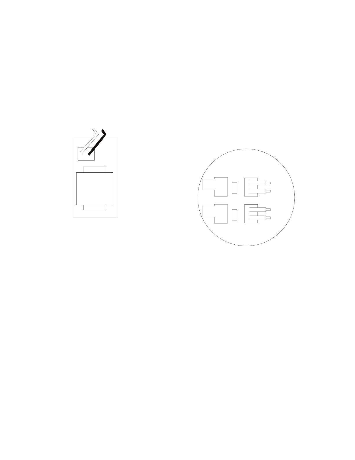
Wiring the Transformer
Wiring the Transformer
The LiteKeeper 4® is factory configured with a 120V
transformer or a 277V transformer. The transformer voltages
are color-coded. The 120V transformer has the power wired
to the black wire and the 277V transformer has the power
wired to the orange wire. The neutral is the white wire.
Connect wires to the transformer. You must provide a
dedicated circuit with circuit protection for the transformer.
Earth ground must be connected to the stud labeled “GND”,
located in the high voltage compartment.
Neutral = White
LK4 Transformer Wiring Information
Line = 120V (Black),
277V (Orange)
120V Transformer
Line = Black
Neutral = White
277V Transformer
Line = Orange
Neutral = White
3. Test branch circuits for short circuits prior to landing
wiring on relays.
4. Connect a 120 or 277 volt, 20 amp max, de-energized
branch circuit breaker to the relay terminal block.
5. Connect the load wiring to the output terminal block.
ote:N Terminal blocks are not polarity sensitive although it
is recommended that line and load be brought into
terminal blocks in the same manner for consistency.
6. Tighten down relay terminal screws. Manufacturer’s
recommended torque rating is 7 lbs-in. (0.59 lbs-foot)
(0.8 Nm).
7. Document relay to circuit information for future
reference.
Relay Rating: 20 Amps
Wire: 10AWG Max.
Line
Load
Line
Load
Connecting Relay Loads
Relay Notes:
1. The standard relay is rated for single-pole load use only.
Connection of 2 pole circuits/loads to the relay will void
the equipment warranty and may result in severe injury
or death, and/or damage to the equipment.
2. Relay ratings are 120 or 277 volt, 20 amp maximum.
3. Relay terminal blocks have a maximum limit of 10AWG
wire.
Relay Wiring
ote:N Neutrals terminate within the adjoining lighting panel.
The standard relay is a simple contact closure, breaking the
line and load wires of a normal circuit. To wire the relay into
the control circuit:
1. Verify that all wire cuttings are removed from the
enclosure.
2. Take the protective shrink-wrap off of the relay cards
AFTER the wire cuttings are removed from the
enclosure.
LiteKeeper 4 Relay Wiring
Connecting Low Voltage Inputs
The LiteKeeper 4® logic board can support up to 4 dry
contact closure switch inputs. Regardless of input type
used, it is recommended that all input wiring be done prior
to applying power Regardless of input type, the following
notes apply.
1. All low voltage wiring is Class 2 wiring.
2. All low voltage wiring must enter the cabinet into the
low voltage section of the enclosure. Low voltage
wiring can be brought into the enclosure from the left
side of the enclosure. Failure to separate high voltage
from low voltage wiring may cause interference with
logic board function.
3. All low voltage wiring must be run in separate conduit
from line voltage wiring.
4. Test all low voltage wiring for shorts to AC ground
before connection to the relay panel.
2
LiteKeeper® 4
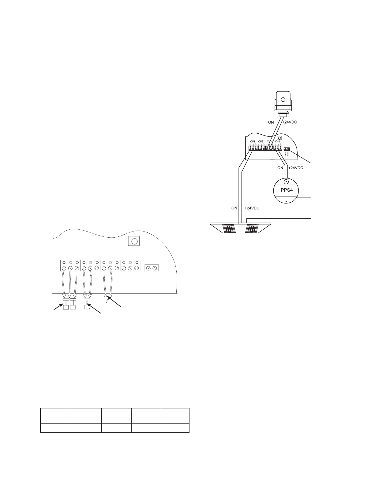
Contact Input Switch Wiring
5. When powering peripheral devices such as motion
sensors and photocells from the LiteKeeper panel,
there may be a limitation on the number of sensors
that can be supported. See the recommendations
below or contact Eaton’s Cooper Controls for further
information.
6. It is recommended that power be removed from the
logic board when doing initial switch input wiring.
Contact Input Switch Wiring
This section describes the wiring for dry contact closure
devices. There are four switch input wiring terminals on the
bottom side of the LiteKeeper 4® low voltage section to
allow for wiring of the dry contact closure devices.
1. Use 18 AWG twisted, unshielded wire for all low
voltage dry contact closure device wiring.
2. Maximum length for dry contact closure device wiring
is 1000 feet.
3. Please see wiring detail below for details on
connections of different devices to the LiteKeeper 4®
system.
Please contact technical support if it is necessary to power
additional sensors beyond the numbers listed above. If
using a combination of devices, please contact technical
support for precise limits on the number of devices the
logic panel can power.
PPS5
Black
(Blue Wire)
(White Wire) (Red Wire)
(Blue Wire)
Yellow & White
Wire Not Used
(Red Wire)
(Red Wire)
Typical Greengate Motion
Sensor Wiring
Black
Black
Black
Contact Input
Photosensor
Wiring
REM PWR DC GND
(Black Wire)
CH1 CH2 CH3
ON
Momentary
ON
OFF
+24
LiteKeeper 4® Low Voltage Switch Wiring
+24
OFF
Toggle
ON
+24
OFF
CH4
ON
OFF
+24
Maintained
+24VDC
DC GND
Contact Input Photosensor and Greengate
Sensor Notes
It is possible to use a contact input photosensor and
Greengate motion sensors in conjunction with the lighting
control system. The LiteKeeper 4® is capable of powering a
number of these devices. Please refer to the chart below for
details on how many devices the transformer can support.
Greengate
PIR Sensor
40 16 20 20 4
Greengate
Dual-Technology
Sensor
Greengate
Ultrasonic
Sensor
PPS-4
Indoor
Photosensor
PPS-5
Outdoor
Photosensor
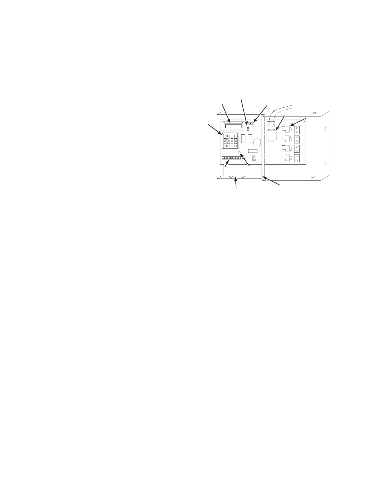
Photocell and Motion Sensor Wiring
Applying Power
1. Once the wiring is complete, make certain that the
enclosure is clean of any wire clippings and that no
fragments are lodged in the relay circuit boards.
2. Ensure that there are no loose wires or exposed wires
that could short to other wires or components.
3. Power-up the unit from the circuit breaker.
4. Once power is applied to the unit, lighting loads may
be operated via the ALL ON/ AUTO/ ALL OFF switch as
necessary.
Manually Controlling Relays
The relays in the enclosure may be controlled before the
logic board is programmed by using the on-board, ALL OFF,
AUTO, ALL ON switch. In the ALL ON position the relay
coils will be energized. In the ALL OFF position, the relay
coils will be de-energized. The middle, AUTO, position allows
the relays to be controlled by the individual relay switches or
from the logic controller.
LiteKeeper® 4
3
System Reset and Clear Commands
System Reset and Clear Commands
Under certain circumstances, you may want to reset the
LiteKeeper 4®. There are two different types of reset
commands available in the LiteKeeper 4® system: a soft
reset command and a clear reset command.
Soft Reset Command: The Soft Reset Command reboots the
microprocessor. It will not cause loss of panel programming.
To perform a Soft Reset Command, press and then
immediately release the reset button located above the
switch wiring channels in the low voltage section. The
display will go blank then read “Initializing…”
Clear Settings Command: A clear settings command is
used to remove all programming from a LiteKeeper 4®
unit. It should be done before programming to the unit
for the first time or when asked to by a Technical Support
representative. Please use caution with this command!
When performing a Clear command, all relay loads will turn
OFF. Use the ALL ON override switch to keep lighting ON if
necessary.
To Perform a Clear Command: Reset the panel, using
the Reset Button. Wait for the screen to initialize. Hit
the key sequence “A, B, C, D, *.” The display will read
“Initializing” again. The unit is now cleared to factory default
programming.
Repair Information
If a repair becomes necessary on your LiteKeeper 4® unit,
please refer all service to Greengate technical support line
at 1-800-553-3879.
Keyboard
Low Voltage Wiring
Compartment
Display
Status LEDs
LIGHTING CONTROL
12:00 01/01/08
2
1
3A
B
5
4
6
9C
7
8
0* #D
ON
ON
+24ONOFFONOFF
+24
OFF
+24
OFF
Low Voltage
Switch Inputs
Item Reference Drawing
Physical
Override
+24
+24VDC
DC GND
High Voltage Wiring Compartment
Reset
Switch
Neutral (White)
120V (Black) or 277V (Orange) Power
Transformer
Barrier Created When High
Voltage Door Is Closed.
Output
Relays
Programming the LiteKeeper 4
The LiteKeeper 4® is programmed either through the
keypad onboard interface or through the optional Keeper
Enterprise Software. Please refer to Programming Guide
that came with the unit to program via the keypad or to your
Keeper Enterprise Manual for programming details. It is
recommended that a Clear Settings command be performed
on the controller before the first programming is done to
clear any test data that may be left in the controller from
factory testing.
4
LiteKeeper® 4
 Loading...