

Page 1
Installation Instructions
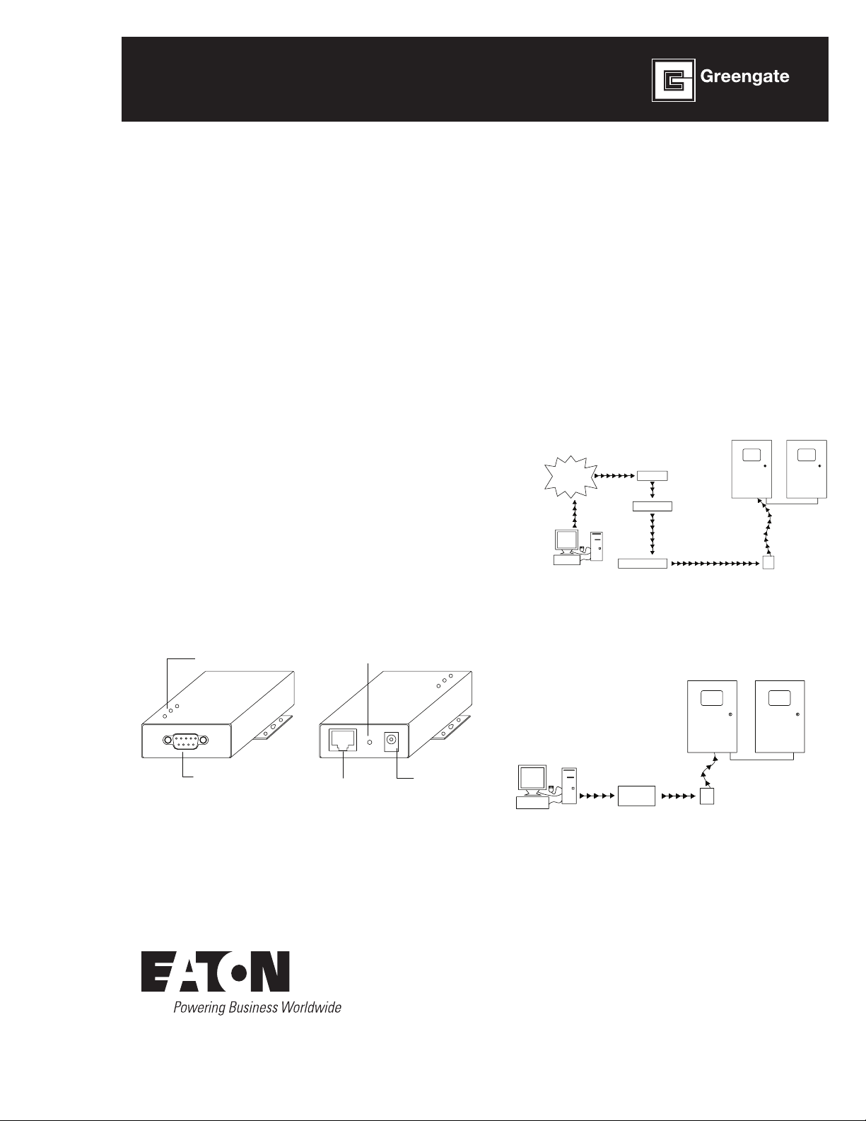
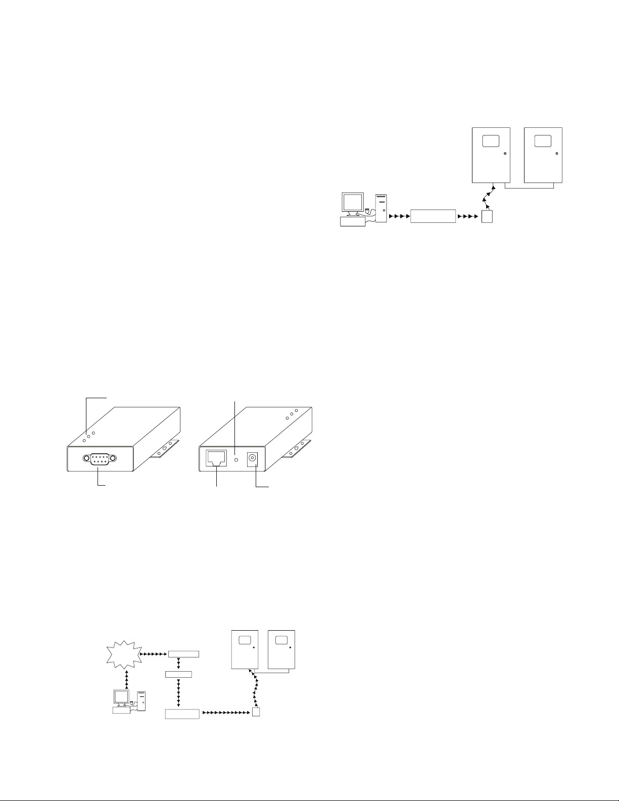
TCP/IP Intranet Connection from a Local Location
Lighting Control Panel Connected
to Lighting Control Network
Ethernet Interface
Module (EIM)
HUB/
SWITCH
Local Computer with
Lighting Software
Ethernet Interface Module Private IP
Address: 10.0.0.1
EIM Port Assigned: 10001
Lighting Software
set up to talk to
lighting control
panels using EIM IP
Address 10.0.0.1
and EIM Port 10001
NOTE: In this scenario, it is not necessary
to access the external, public internet. The
Ethernet Interface Module may be
accessed directly.
Model# EIM
Ethernet Interface Module
Module d’interface Ethernet
Del software de interfaz de Ethernet
INS #
General Information
The Ethernet Interface Module (EIM) is a device that
makes communications from a PC to a Greengate
panel or network of panels possible over an Internet
connection. The PC can be local within the building
complex or located at a remote location.
The Ethernet Interface Module (EIM) converts data
packets sent over the TCP/IP connection to RS-232
communications. One Ethernet Interface Module (EIM)
is needed per Lighting Control Network unless using the
VisionTouch software. If VisionTouch software is being
used, it is recommended that an Ethernet Interface
Module be dedicated to VisionTouch use. Please contact
technical support for further details. If panels are not
networked, one Ethernet Interface Module (EIM) will be
needed per panel. The Ethernet Interface Module (EIM)
Device Package comes with the following:
Ethernet Interface Module (EIM) device
AC Power Adapter
Cable Package (Contains a crossover cable for
configuration, one phone style serial cable and adapter
head for connection to the lighting panel.)
Status LEDs
Reset Button
Typical Layouts
The Ethernet Interface Module may be used to allow
access only from within the internal building LAN or
may also be set up by a qualified network administrator
for external access through the internet. The following
pictures depict these types of configurations.
TCP/IP Internet Connection from a Remote Location
Lighting Control Panel Connected
to Lighting Control Network
INTERNET
Lighting Software set
up to talk to lighting
control panels using
Firewall IP Address
64.30.7.31 and
Firewall
Port 10001.
Remote Computer
with Lighting Software
ROUTER
FIREWALL
HUB/SWITCH
Firewall Public IP Address: 64.30.7.31
Firewall Port for EIM: 10001 - This
should be the same port number as
the port assigned in the EIM
Firewall Port 10001 is assigned to
direct all traffic coming to this port to
private IP Address 10.0.0.1
Ethernet Interface Module
Private IP Address: 10.0.0.1
EIM Port Assigned: 10001
Ethernet
Interface
Module
(EIM)
RS232 Port
RJ54 Ethernet Port
Power
Input
Page 2
Customer Obligations
Customer Obligations
The Ethernet Interface Module (EIM) must be configured by
a qualified network administrator. The customer must also
provide an IP address for each Ethernet Interface Module
(EIM) Device being used and be able to support TCP/IP
communications protocol. It may be necessary for the site’s
network administrator to perform firewall programming to
allow for remote access to the device depending on system
setup and desired computer access.
Ethernet Interface Module Configuration
In order for the Ethernet Interface Module (EIM) to work
properly with your application, it will be necessary for the
network administrator to set up the Ethernet Interface
Module (EIM) device(s). Please follow the steps outlined in
this instruction in order for the unit to communicate properly
with the lighting control system. Greengate recommends
using the built-in configuration web server pages in the unit
as the method of configuration.
The instructions that follow describe the setup of the device
using the web server pages.
The following instructions describe what methodology is
used to configure the unit. Regardless of what the important
settings that must be configured, include the following:
1. IP Address must be statically assigned
2. Subnet mask must be set
3. Default Gateway Address must be assigned
4. The IP Port must be configured with a port number.
Port # 10001 is usually an unused port that may be
assigned.
5. The serial settings must be configured properly per the
instructions for communication to the lighting control
network.
Failure to configure the above settings will result in the
failure of the device to communicate with the lighting
control system.
4. Under the LAN and high-speed internet option, find the
Local Area Connection for your network interface card.
(you may have several listed – if you are not connected
to your building LAN, it will more than likely be the
connection that states “Network cable unplugged”)
5. Right click on the connection and choose Properties
from the pop-up window.
6. In the General tab, scroll down the list of items and
highlight the option for Internet Protocol (TCP/IP).
7. Click on the Properties button.
8. Make note of the current settings so that you can
reconfigure them after configuration is complete.
9. Select the Use the following IP address radial button.
10. Type in an IP Address of 192.168.127.1.
11. Type in the subnet mask 255.255.255.0.
12. Leave all other fields blank.
13. Click on the OK button.
14. Click on the Close button. It may take several seconds
for the new IP settings to take effect.
15. Connect the crossover cable provided from your
computer’s Ethernet port to the EIM’s Ethernet port.
16. Open your internet browser.
1 7. Make certain that cookies are enabled. (please refer
to your internet browser help file for information on
enabling cookies for your browser version).
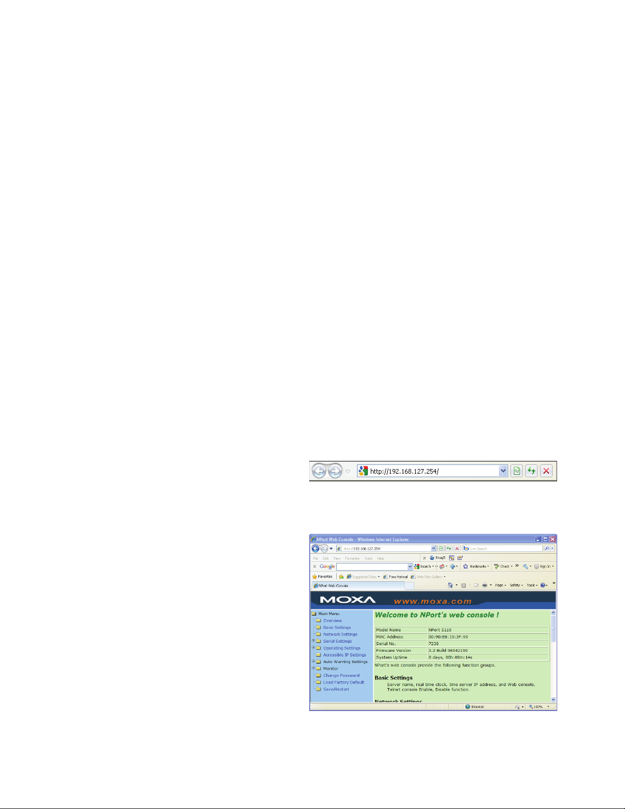
18. In the browser address window, type in the default EIM
address 192.168.127.254 and press the Enter key.
19. You will be brought to the web console configuration
tool for the EIM.
Making the Initial Connection
Before you begin the device configuration, it will be
necessary to configure your Network Interface Card
connection to be on the same subnet as the EIM’s
default IP Address. The default address of the EIM is
192.168.127.254 before configuration. To change your
computer’s TCP/IP settings (Windows XP Steps Shown):
1. Disconnect your LAN Ethernet connection cable from
your computer.
2. Access the Windows Control Panel.
3. Select the Network Connections option.
2
Ethernet Interface Module
Page 3
Configuration Settings in the EIM
Configuration Settings in the EIM
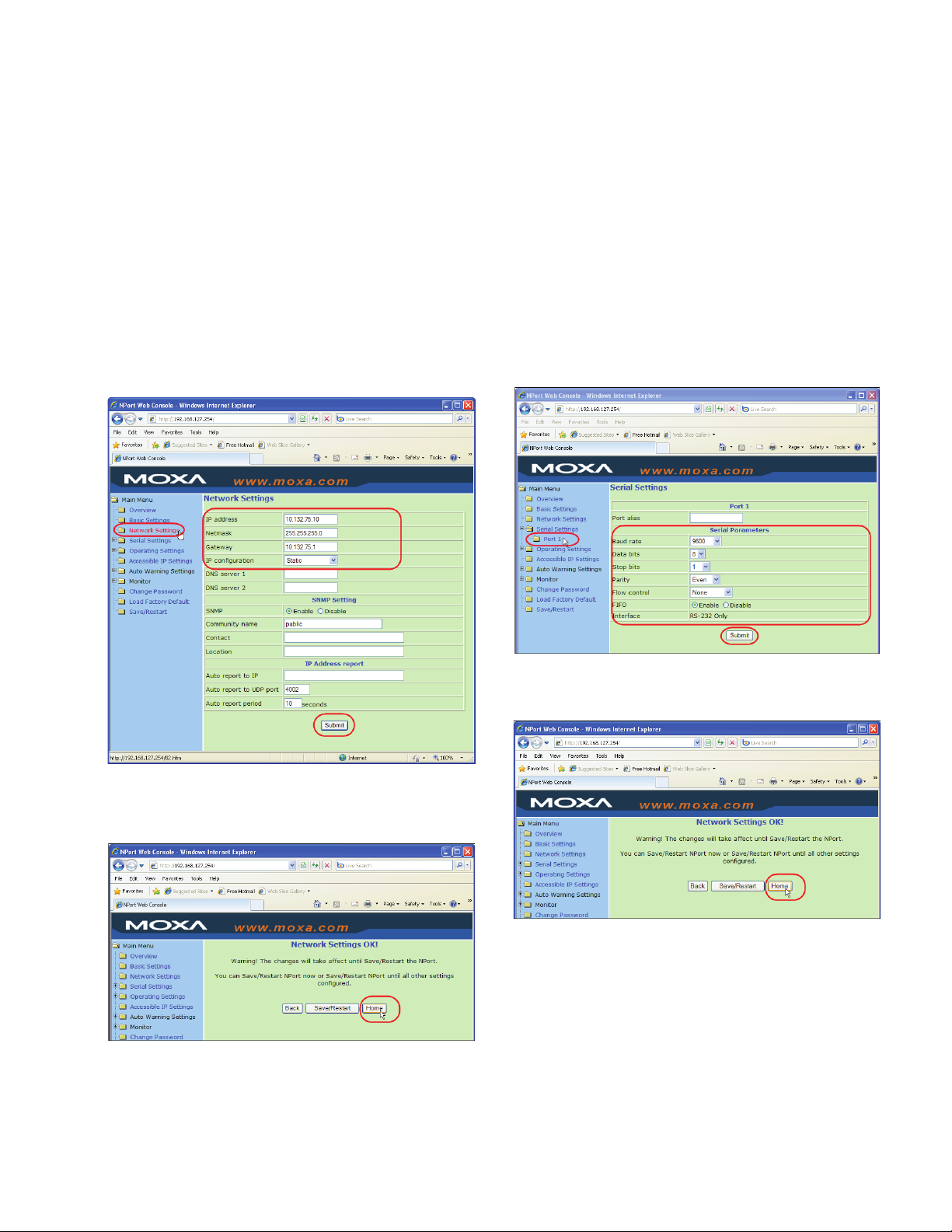
1. In the menu tree on the left side of the screen, select
the Network Settings folder.
2. In the Network Settings screen, define the following
items:
IP Address
Netmask
Gateway IP Address
IP Configuration – make certain this is set to Static
3. Select the Submit button.
6. Select the Port 1 folder within the Serial Settings folder.
7. In the Serial Settings screen, set the following
parameters:
Baud rate: 9600
Data bits: 8
Stop bits: 1
Parity: Even
Flow Control: None
FIFO: Enable
8. Select the Submit button.
4. In the Network Settings OK screen, select the Home
button.
5. In the menu tree on the left side of the screen, expand
the Serial Settings folder.
9. In the Serial Settings OK screen, select the Home
button.
Ethernet Interface Module
3
Page 4
Connecting the EIM to the Lighting Panel
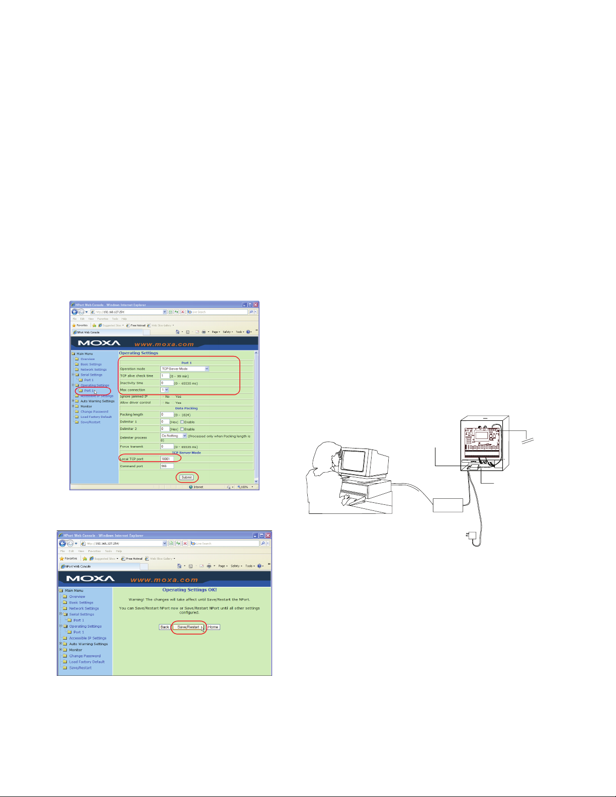
10. In the menu tree on the left side of the screen, expand
the Operating Settings folder.
1. Select the Port 1 folder within the Operating Settings
folder.
2. In the Operating Settings screen, set the following
parameters:
Operation Mode: TCP Server Mode
TCP alive check time: 1 minute
Inactivity time: 0
Max Connection: 4
Local TCP port: 10001 recommended (or other port
specified by the IT administrator)
Other fields not identified should be left at default
settings shown
3. Select the Submit button.
Remember to reset your computer’s network TCP/IP
settings to their original settings. If you need to reconnect
through the web server pages, you will need to make
certain that your computer is configured to communicate
on the same subnet as the EIM device. Instead of typing in
the default address in the browser address, you will need to
use the unit’s assigned IP Address.
Connecting the EIM to the Lighting Panel
After configuration is complete, it will be necessary to
connect the device to the lighting control panel using the
following steps:
1. Connect the supplied phone style communications
cable to the female 9 pin adapter head provided.
2. Connect the 9 pin adapter head to the Ethernet
Interface Module’s serial port.
3. Connect the other end of the phone style
communications cable to the RJ11 style COM port on
the Lighting Control Panel. (on some controllers there
are two RJ11 style connectors. Please connect the
cable to connector labeled RS-232.)
4. Connect one end of the Ethernet cable to the Ethernet
Interface Module RJ45 port and the other end of the
cable to the Ethernet network.
12. Plug in the power adapter supplied with the device.
4. In the Operating Settings OK screen, select the Save/
Restart button.
11. Once the Save/Restart OK screen appears, close the
web browser. Configuration is complete.
The Ethernet Interface Module (EIM)
can be connected to any controller in the network.
Lighting Control Software
Ethernet Interface
Module (EIM)
HUB
Building LAN
AC Adapter
LED4LED5
RESET
POWER
STATUSNET
50-022180-02
C
PCI 2005
LED2
LED3
LED1
54-022180-
RSC POWERRSC LINK
CAN-TXCAN-RX
J7
J1
TMS
TDI
TDO
TCK
GND
VCC
JTAG
ANALOGS
ANALOG COMAN1AN2AN3AN4
TB3
17CH
18
PCI-NET
J2
J4
J3
J5
J6
DIGITA
RS-232
PCI-NETPCI-NET
TB1
SR1
IND1
C29
CW
J9
REM
LCD
ADJ
J10
D6D5D4D3
C43
TB2
ICD LINK
LED6
LSC
TEST
ON +24 OFF LSOON +24 OFF LSOON +24 OFF LSOON +24 OFF LSOON +24 OFF LSOON +24 OFF LSOON +24 OFF LSOON +24 OFF LSOON +24 OFF LSOON +24 OFF LSOON +24 OFF LSOON +24 OFF LSOON +24 OFF LSOON +24 OFF LSOON +24 OFF LSOON +24 OFF LSO
TP1
CHCHCHCHCHCHCHCHCHCHCHCHCHCHCHCHCHCHCHCHCHCHCHCHCHCHCHCHCHCH1CH
ON +24 OFF LSOON +24 OFF LSOON +24 OFF LSOON +24 OFF LSOON +24 OFF LSOON +24 OFF LSOON +24 OFF LSOON +24 OFF LSOON +24 OFF LSOON +24 OFF LSOON +24 OFF LSOON +24 OFF LSOON +24 OFF LSOON +24 OFF LSOON +24 OFF LSOON +24 OFF LSO
RS-232 Phone Style
Cable with Adapter
Cable Head
NET+NET
J8
TERM
NET
LOCAL
REM
PWR
GND+24
RS-485 Network
16321531143013291228112710269258247236225214203192
to Other Lighting
Control Panels
4
Ethernet Interface Module
Page 5

Diagnostic LEDs
Diagnostic LEDs
There are three LEDs located on the top of the EIM unit.
They can be useful in diagnosing proper operation as well
as troubleshooting if necessary. The EIM will indicate a valid
connection to the Ethernet in the following ways:
The Ethernet LED maintains a solid green color when
connected to a 100 Mbps Ethernet network
The Ethernet LED maintains a solid orange color when
connected to a 10 Mbps Ethernet network
The Ethernet LED will flash when Ethernet packets are
being transmitted or received
LED Name LED Color LED Function
Ready
Red
Green
OFF
Steady ON: Power is on and the EIM
is booting.
Blinking: Indicates an IP Conflict
Steady ON: Power is on and the EIM
is functioning normally
Power is OFF or power error
condition exists.
Reset Button
There is an onboard reset button located between the
power connection and Ethernet connection on the EIM.
Press the Reset button continuously for 5 seconds to
load factory defaults: Use a pointed object, such as a
straightened paper clip or toothpick, to press the reset
button.
This will cause the Ready LED to blink ON and OFF. The
factory defaults will be loaded once the Ready LED stops
blinking (after about 5 seconds). At this point, you should
release the reset button.
It is possible to limit the reset function for the first 60
seconds from initial power-up by accessing the Basic
Settings screen in the webserver configuration mode and
selecting the “Yes” option for Reset Button Protect.
Link
Tx/Rx
Orange
Green
OFF
Orange
Green
OFF
10 Mbps Ethernet Connection
100 Mbps Ethernet Connection
Ethernet cable is disconnected or has
a short.
Serial port is receiving data
Serial port is transmitting data
No data is being transmitted or
received through the serial port.
Ethernet Interface Module
5
Page 6

Renseignements généraux
Panneau de commande de l'éclairage raccordé au
Raccordement Internet TCP/IP à distance
Raccordement Intranet TCP/IP local
Panneau de commande de l'éclairage raccordéau
réseau de commande de l'éclairage
Interface Ethernet
Module (MIE)
CONCENTRATEUR/
COMMUTATEUR
Ordinateur local avec
logiciel d’éclairage
Adresse IP privée du module
d'interface Ethernet (MIE): 10.0.0.1
Port attribué au MIE: 10001
Le logiciel d'éclairage est configuré
pour communiquer avec les panneaux
de commande de l'éclairage à partir
de l'adresse IP du MIE 10.0.0.1 et du
port du MIE 10001.
REMARQUE: Avec ce scénario, il n'est pas
nécessaire d'accéder au réseau Internet
externe et public. Il est possible d'accéder
directementau module d'interface Ethernet.
Renseignements généraux
Le module d’interface Ethernet (MIE) est un dispositif qui
permet la communication d’un ordinateur personnel avec un
panneau ou un réseau de panneau Greengate à l’aide d’une
connexion Internet. L’ordinateur personnel peut être situé
dans le même immeuble ou dans un lieu éloigné.
Le module d’interface Ethernet (MIE) convertit les
paquets de données transmis par la connexion TCP/IP aux
communications RS-232. Un module d’interface Ethernet
(MIE) est nécessaire par réseau de régulation d’éclairage à
moins d’utiliser le logiciel VisionTouch. Lorsque le logiciel
VisionTouch est utilisé, il est recommandé de dédier un
module d’interface Ethernet à l’usage de VisionTouch.
Pour plus de détails, veuillez communiquer avec le soutien
technique. Si les panneaux ne fonctionnent pas en réseau,
un module d’interface Ethernet (MIE) par panneau est
nécessaire. La trousse du module d’interface Ethernet (MIE)
est fournie avec les éléments suivants:
Module d’interface Ethernet (MIE)
Adaptateur de CA
Trousse de câbles (contient un câble inverseur pour la
configuration, un câble série de style téléphonique et une
tête d’adaptateur pour le panneau d’éclairage.)
DEL d'état
Bouton de réinitialisation
Obligations du client
Le module d’interface Ethernet (MIE) doit être configuré par
un administrateur de réseau. Le client doit également
fournir une adresse IP pour chaque module d’interface
Ethernet (MIE) utilisé et être en mesure de prendre en
charge le protocole de communication TCP/IP. Il peut être
nécessaire, selon la configuration du système et l’accès
nécessaire aux ordinateurs, que l’administrateur de réseau
du site programme le pare-feu afin qu’il permette l’accès à
distance au dispositif.
Port RS232
Dispositions types
Le module d’interface Ethernet peut servir à permettre
l’accès uniquement à partir du LAN interne de l’immeuble
ou il peut être configuré par un administrateur de réseau
qualifié pour permettre l’accès externe par l’entremise
d’Internet. L’illustration suivante décrit ces types de
configuration.
INTERNET
Logiciel d’éclairage
configurépour
communiquer avec le
panneau de
commande de
l'éclairage à
partir de
l'adresse IP
64.30.7.31
du pare-feu
etdu port 10001
du pare-feu
Ordinateur à
distance avec
logiciel d’éclairage
RJ54 Port Ethernet
réseau de commande de l'éclairage
ROUTEUR
PARE-FEU
Adresse IP du pare-feu public: 64.30.7,31
Port du pare-feu pour le MIE: 10001.
Cenuméro de port devrait être le mêmeque
celui du port attribuée dans du MIELe port
10001 du pare-feu est
attribuéafin de diriger tout le trafic entrant
versl'adresse IP privée 10.0.0.1
CONCENTRATEUR/
COMMUTATEUR
Module d'interface Ethernet
Adresse IP privée: 10.0.0.1
Port attribué au MIE: 10001
Alimentation
électrique
Interface
Ethernet
Module
(MIE)
Configuration du module d’interface Ethernet
Afin de permettre le fonctionnement adéquat du ou des
module(s) d’interface Ethernet (MIE) avec votre application,
l’administrateur de réseau du site devra le ou les configurer.
Veuillez suivre les étapes décrites dans ce mode d’emploi afin
de permettre une communication adéquate entre l’appareil et le
système de régulation de l’éclairage. Greengate recommande
d’utiliser les pages intégrées de configuration de serveur Web
de l’appareil pour le configurer.
Les directives qui suivent décrivent la configuration
de l’appareil à l’aide des pages de serveur Web. Les
directives qui suivent décrivent la méthodologie utilisée
pour configurer l’appareil. Quels que soient les importants
paramètres à configurer, il faut inclure les éléments
suivants:
1. L’adresse IP doit être attribuée de manière statique.
2. Le filtre d’adresse locale doit être configuré.
3. L’adresse de passerelle par défaut doit être attribuée.
4. S’il y a un numéro de port IP, il doit être configuré. Le
port nº 10001 est généralement libre et il peut être
attribué.
5. Les paramètres série doivent être adéquatement
configurés selon les directives de communication avec
le réseau de régulation de l’éclairage.
Négliger de configurer les paramètres ci-dessus empêchera
l’appareil de communiquer avec le système de régulation de
l’éclairage.
6
Module d’interface Ethernet
Page 7

Établir la connexion initiale
Établir la connexion initiale
Avant de commencer la configuration de l’appareil, il est
nécessaire de configurer d’abord votre connexion à la carte
d’interface réseau afin de partager le même sous-réseau
que l’adresse IP par défaut du MIE. L’adresse par défaut
du MIE est 192.168.127.254 avant la configuration. Pour
modifier les paramètres TCP/IP (les étapes sont indiquées
pour Windows XP):
1. Débranchez le câble de raccordement Ethernet LAN de
l’ordinateur.
6. Accédez au panneau de configuration Windows.
7. Sélectionnez ensuite l’option Connexions réseau et
Internet.
8. Sous l’onglet LAN et Internet haute vitesse, trouvez
la connexion au réseau local correspondant à votre
carte d’interface réseau. (Il peut y en avoir plusieurs.
Si l’ordinateur n’est pas relié au réseau LAN de
l’immeuble, il s’agit probablement de la connexion
portant la mention «Câble réseau débranché».)
9. Cliquez sur la connexion avec le bouton droit de la
souris et sélectionnez Propriétés dans la fenêtre
contextuelle.
10. Sous l’onglet Général, parcourez la liste d’éléments et
sélectionnez l’option pour le protocole Internet (TCP/IP).
11. Cliquez sur le bouton Propriétés.
2. Notez les paramètres actuels afin de pouvoir les rétablir
une fois la configuration terminée.
12. Sélectionnez le bouton radial Utiliser l’adresse IP
suivante.
13. Entrez l’adresse IP 192.168.127.1.
14. Entrez le filtre d’adresse locale 255.255.255.0.
15. Laissez les autres champs vides.
16. Cliquez sur le bouton OK.
1 7. Cliquez sur le bouton Close (fermer). Quelques minutes
sont nécessaires que les nouveaux paramètres IP
soient effectifs.
18. Raccordez le port Ethernet de votre ordinateur au port
Ethernet du MIE à l’aide du câble inverseur fourni.
19. Ouvrez le navigateur Internet.
20. Assurez-vous que les témoins («cookies ») sont
autorisés (consultez le fichier d’aide de votre navigateur
Internet pour savoir comment accepter les témoins
pour votre version du navigateur).
21. Dans la fenêtre d’adresse du navigateur, entrez
l’adresse par défaut du MIE, 192.168.127.254 et
appuyez sur ENTER.
22. Cela ouvrira l’outil de configuration du MIE pour la
console Web.
Paramètres de configuration du MIE
1. Dans l’arborescence à gauche de l’écran, sélectionnez
le dossier Paramètres du réseau.
23. À l’écran de confirmation des paramètres du réseau,
définissez les éléments suivants:
Adresse IP
Filtre d’adresse locale
Adresse IP de passerelle
Configuration IP; assurez-vous qu’elle est réglée à
«statique»
24. Sélectionnez le bouton Transmettre.
Module d’interface Ethernet
7
Page 8

Paramètres de configuration du MIE
25. À l’écran de confirmation des paramètres du réseau,
sélectionnez le bouton Accueil
26. Dans l’arborescence à gauche de l’écran, ouvrez le
dossier Paramètres série.
27. Sélectionnez le sous-dossier Port 1 dans le dossier
Paramètres série.
28. À l’écran de confirmation des paramètres série,
configurez les éléments suivants:
Débit en bauds: 9600
Bits d’information: 8
Bits d’arrêt: 1
Parité: uniforme
Contrôle de flux: aucun
FEPS: activer
29. Sélectionnez le bouton Transmettre.
30. À l’écran de confirmation des paramètres de série,
sélectionnez le bouton Accueil.
31. Dans l’arborescence à gauche de l’écran, ouvrez le
dossier Paramètres de fonctionnement.
32. Sélectionnez le sous-dossier Port 1 dans le dossier
Paramètres de fonctionnement.
33. À l’écran de confirmation des paramètres de
fonctionnement, configurez les éléments suivants:
Mode de fonctionnement: mode serveur TCP
Durée de vérification en direct TCP: 1 minute
Temps d’inactivité: 0
Connexion max.: 4
Port TCP local: 10001 recommandé (ou tout autre port
indiqué par l’administrateur de TI)
Laissez les paramètres des champs qui n’ont pas été
mentionnés à leur valeur par défaut.
34. Sélectionnez le bouton Transmettre.
8
Module d’interface Ethernet
Page 9

Raccordement du MIE au panneau de commande de l’éclairage
avec tête d'adaptateur
Réseau RS-485
de commande
35. À l’écran de confirmation des paramètres de
fonctionnement, sélectionnez le bouton Enregistrer/
redémarrer.
36. Fermez le navigateur Web lorsque l’écran Enregistrer/
redémarrer avec le bouton apparaît. La configuration est
maintenant terminée.
N’oubliez pas de restaurer les paramètres réseau TCP/IP à
leur configuration d’origine. S’il est nécessaire de rétablir la
connexion à partir des pages du serveur Web, assurez-vous
que l’ordinateur est configuré pour communiquer par le
même sous-réseau que l’appareil de MIE. Au lieu d’entrer
l’adresse par défaut du navigateur, il faudra utiliser l’adresse
IP attribuée à l’appareil.
Le module d'interface Ethernet (MIE) peut être raccordé à
n'importe quel régulateur du réseau.
Interface Ethernet
Module (MIE)
Logiciel de commande d’éclairage
Adaptateur de CA
CONCENTRATEUR
LAN de l'immeuble
LED4LED5
RESET
POWER
STATUSNET
50-022180-02
C
PCI 2005
LED2
LED3
LED1
54-022180-
RSC POWERRSC LINK
CAN-TXCAN-RX
J7
J1
TMS
TDI
TDO
TCK
GND
VCC
JTAG
ANALOGS
ANALOG COMAN1AN2AN3AN4
TB3
18
17CH
PCI-NET
J2
J4
J3
J5
J6
DIGITA
RS-232
PCI-NETPCI-NET
NET+NET
TB1
J8
TERM
NET
SR1
IND1
C29
CW
J9
REM
LCD
LOCAL
ADJ
J10
D6D5D4D3
C43
REM
PWR
GND+24
TB2
ICD LINK
LED6
LSC
TEST
ON +24 OFF LSOON +24 OFF LSOON +24 OFF LSOON +24 OFF LSOON +24 OFF LSOON +24 OFF LSOON +24 OFF LSOON +24 OFF LSOON +24 OFF LSOON +24 OFF LSOON +24 OFF LSOON +24 OFF LSOON +24 OFF LSOON +24 OFF LSOON +24 OFF LSOON +24 OFF LSO
TP1
16321531143013291228112710269258247236225214203192
CHCHCHCHCHCHCHCHCHCHCHCHCHCHCHCHCHCHCHCHCHCHCHCHCHCHCHCHCHCH1CH
versles autres
ON +24 OFF LSOON +24 OFF LSOON +24 OFF LSOON +24 OFF LSOON +24 OFF LSOON +24 OFF LSOON +24 OFF LSOON +24 OFF LSOON +24 OFF LSOON +24 OFF LSOON +24 OFF LSOON +24 OFF LSOON +24 OFF LSOON +24 OFF LSOON +24 OFF LSOON +24 OFF LSO
panneaux
de l'éclairage
Câble de style
téléphonique RS-232
Raccordement du MIE au panneau de commande de l’éclairage
Une fois la configuration terminée, il est nécessaire de
raccorder l’appareil au panneau de commande de l’éclairage
et suivant les étapes suivantes:
1. Branchez le câble série de style téléphonique dans
l’adaptateur femelle à 9 broches fourni.
2. Branchez la tête de l’adaptateur à 9 broches au port
série du module d’interface au Ethernet.
3. Branchez l’autre extrémité du câble de communication
de style téléphonique au port de communications de
style RJ11 du panneau de commande de l’éclairage.
(Certains régulateurs possèdent deux ports de style
RJ11. Il faut brancher le câble au connecteur portant
l’étiquette RS-232.)
4. Branchez une extrémité du câble Ethernet au port RJ45
du module d’interface Ethernet et l’autre extrémité du
câble au réseau Ethernet.
5. Branchez le bloc d’alimentation fourni avec l’appareil.
Module d’interface Ethernet
9
Page 10

DEL de diagnostic
DEL de diagnostic
On retrouve 3 DEL situés au sommet de l’appareil de MIE.
Ils servent à confirmer le bon fonctionnement de l’appareil
ainsi qu’au dépannage, si nécessaire. Le MIE indiquera la
présence d’une connexion valide au réseau Ethernet de
l’une des manières suivantes:
Le témoin DEL d’Ethernet conserve la couleur verte
lorsqu’il est raccordé à un réseau Ethernet de 100 Mo/s
Le témoin DEL d’Ethernet conserve la couleur orangée
lorsqu’il est raccordé à un réseau Ethernet de 10 Mo/s
Le témoin DEL d’Ethernet clignote lors que des paquets
Nom du
DEL
Prêt
Couleur
du DEL
Rouge
Vert
ÉTEINT
Fonction du DEL
ALLUMÉ et stable: l'appareil est sous tension
et le MIE démarre
Clignote: indique un conflit d'adresses IP
ALLUMÉ et stable: l'appareil est sous tension
et le MIE fonctionne normalement
L'appareil est éteint ou il y a un
problème d'alimentation électrique.
Bouton de réinitialisation
Un bouton de réinitialisation se trouve sur le panneau entre
la prise d’alimentation et la connexion Ethernet du MIE.
Maintenez le bouton de réinitialisation enfoncé pendant
5 secondes pour revenir aux paramètres par défaut de
l’appareil: utilisez un objet pointu, comme un trombone
déplié ou un cure-dent pour appuyer sur le bouton de
réinitialisation.
Cela provoquera le clignotement du témoin DEL qui indique
que l’appareil est prêt. Les paramètres par défaut de
l’appareil sont alors rechargés et le témoin DEL arrête de
clignoter (après environ 5 secondes). Il faut alors libérer le
bouton.
Il est possible de limiter la fonction de réinitialisation
pendant les 60 secondes qui suivent la mise en marche
initiale en accédant à l’écran des paramètres de base du
mode de configuration du serveur Web et en sélectionnant
l’option «oui» de la fonction de protection du bouton de
réinitialisation.
Liaison
Tx/Rx
Orange
Vert
ÉTEINT
Orange
Vert
ÉTEINT
Connexion à Ethernet de 10 Mo/s
Connexion à Ethernet de 100 Mo/s
Le câble Ethernet est débranché ou
court-circuité.
Le port série reçoit des données.
Le port série transmet des données.
Aucune donnée n'est transmise ni reçue par
le port série.
10
Module d’interface Ethernet
Page 11
Información general
Conexión a Intranet TCP/IP desde una ubicación local
Panel de control de iluminación conectado
con la red de control de iluminación
Interfaz Ethernet
Módulo (EIM)
CONCENTRADOR/
CONMUTADOR
Computadora local conIP privada
del módulo de interfaz de Ethernet
del software de iluminación
Dirección: 10.0.0.1
Puerto EIM asignado: 10001
Ajuste del software de iluminación
para su comunicación con los paneles
de control de iluminaciónpor medio de
una dirección IP del EIM 10.0.0.1 y
puerto 10001 del EIM
NOTA: En este escenario, no es
necesarioacceder a una conexión de
Internet externa y pública. Al módulo de
interfaz de Ethernet se puede accederse
directamente.
El módulo de interfaz de Ethernet (EIM, por su sigla en
inglés) es un dispositivo que posibilita la comunicación
desde una PC a un panel o red de paneles Greengate por
medio de una conexión a Internet. La PC puede ser local y
estar dentro de un complejo de edificios o ubicarse en un
lugar remoto.
El módulo de interfaz de Ethernet (EIM) convierte los
paquetes de datos enviados a través de una conexión
TCP/IP en comunicaciones RS-232. Se necesita un módulo
de interfaz de Ethernet (EIM) por cada red de control de
iluminación, a menos que se utilice el software VisionTouch.
Si está utilizando el software VisionTouch, se recomienda
que se dedique un módulo de interfaz de Ethernet a dicho
software. Contacte a Soporte Técnico para obtener más
detalles. Si los paneles están conectados a una red, se
necesitará un módulo de interfaz de Ethernet (EIM) por
cada panel. El paquete del dispositivo del EIM viene con los
siguientes elementos:
Dispositivo de módulo de interfaz de Ethernet (EIM)
Adaptador de alimentación de CA
El paquete de cables (contiene un cable cruzado para su
configuración, un cable serial estilo telefónico y
un cabezal adaptador para su conexión al panel de
iluminación)
Estado de los LED
Botón de reinicio
Información general
Obligaciones del cliente
El módulo de interfaz de Ethernet (EIM) debe ser
configurado por un administrador de redes cualificado.
Además, el cliente debe proveer una dirección IP por cada
dispositivo EIM que esté en uso y este debe poder soportar
el protocolo de comunicaciones TCP/IP. El administrador
de redes del sitio puede tener que realizar la programación
del firewall para permitir el acceso remoto al dispositivo,
según la configuración del sistema y el acceso deseado a la
computadora.
Puerto RS232
RJ54 Puerto Ethernet
Presentaciones típicas
El módulo de interfaz de Ethernet puede usarse para
posibilitar el acceso solo dentro de la red LAN interna
del edificio o puede también ser configurado por un
administrador de redes cualificado únicamente para
obtener acceso externo a través de Internet. Las siguientes
imágenes ilustran estos tipos de configuraciones.
Conexión de Internet TCP/IP desde una ubicación remota
Panel de control de iluminación conectado
con la red de control de iluminación
Ajuste del software
de iluminación para
su comunicación
con los paneles
de control de
iluminación por
mediode la
dirección
IP del firewall
64.30.7.31 y
el puerto 10001
del firewall.
INTERNET
Computadora
remota con módulo de
interfaz de Ethernet
ENRUTADOR
FIREWALL
Dirección IP pública del firewall: 64.30.7.31
Puerto del firewall para el EIM: 10001.
Este puerto debe tener el mismo número que
el puerto asignado en el puerto 10001 del
firewall del EIM para dirigir el tráfico de entrada
en este puerto hacia la dirección de
IP privada 10.0.0.1
CONCENTRADOR/
CONMUTADOR
Entrada de
alimentación
Interfaz
Ethernet
Módulo
(EIM)
del software de iluminación
Dirección IP privada: 10.0.0.1
Puerto EIM asignado: 10001
Configuración del módulo de interfaz de Ethernet
A fines de que el EIM funcione correctamente con su
aplicación, será necesario que el administrador de redes
configure el(los) dispositivo(s) del EIM. Siga los pasos
detallados en estas instrucciones, a los fines de que la
unidad se comunique correctamente con el sistema de
control de iluminación. Greengate recomienda el uso de la
configuración incorporada de las páginas web del servidor
en la unidad como método de configuración.
Las siguientes instrucciones describen la configuración del
dispositivo usando las páginas web del servidor.
Las siguientes instrucciones describen la metodología
utilizada para configurar la unidad. Independientemente de
los ajustes importantes que deben configurarse, incluya los
siguientes:
1. La dirección IP debe estar asignada de manera estática.
2. La máscara de subred debe estar configurada.
3. Se debe asignar una dirección de puerta de enlace
predeterminada.
4. El puerto IP debe configurarse si es un número de
puerto. El puerto N.° 10001 usualmente es un puerto
sin usar que puede ser asignado.
5. Los ajustes de serie deben configurarse correctamente
de acuerdo a las instrucciones para comunicación con
la red del control de iluminación.
De no configurarse los ajustes anteriores, se generará una falla
Module d’interface Ethernet
11
Page 12

Ajustes de configuraciones en el EIM
en la comunicación del dispositivo con el sistema de control de
iluminación.
Realización de la conexión inicial
Antes de comenzar con la configuración del dispositivo, será
necesario configurar la conexión de su tarjeta de interfaz
de red para que esté en la misma subred que la dirección
IP predeterminada del EIM. La dirección predeterminada
del EIM es 192.168.127.254 antes de su configuración.
Para modificar los ajustes TCP/IP de su computadora (se
muestran los pasos con Windows XP):
1. Desconecte el cable de conexión Ethernet LAN de su
computadora.
2. Acceda al panel de control de Windows.
3. Seleccione la opción de Conexiones de redes.
4. En la opción de LAN e Internet de alta velocidad,
encuentre la Conexión de área local de su tarjeta de
interfaz de red. (Puede tener varias en la lista; si no
está conectado a la red LAN de su edificio, será más
probable que sea la conexión que dice “Cable de red
desconectado”).
5. Haga clic con el botón derecho en la conexión y elija
Propiedades desde la ventana emergente.
6. En la pestaña General, deslícese hacia abajo de la lista
de elementos y resalte la opción Protocolo de Internet
(TCP/IP).
7. Haga clic en el botón Propiedades.
8. Tome nota de las configuraciones actuales para poder
reconfigurarlas luego de finalizar la configuración.
9. Seleccione el botón de opción Utilizar la siguiente
dirección IP.
10. Escriba la dirección IP 192.168.127.1.
11. Escriba la máscara de subred 255.255.255.0.
12. Deje todos los otros campos en blanco.
13. Haga clic en el botón OK.
14. Haga clic en el botón Cerrar. Puede tomar varios
segundos hasta que las configuraciones de IP entren
en efecto.
15. Conecte el cable cruzado incluido del puerto Ethernet
de su computadora en el puerto Ethernet del EIM.
16. Abra su explorador de Internet.
1 7. Asegúrese de que las cookies estén habilitadas.
(Remítase al archivo de ayuda de su explorador de
Internet para obtener información sobre la habilitación
de las cookies en la versión de su explorador.)
18. En la ventana de dirección del explorador, escriba la
dirección del EIM predeterminada 192.168.127.254 y
presione la tecla Enter.
19. Será dirigido a la herramienta de configuración de la
consola web del EIM.
Ajustes de configuraciones en el EIM
1. En el árbol de menú en el lateral izquierdo de la
pantalla, seleccione la carpeta Configuraciones de red.
2. En la pantalla de Configuraciones de red, defina los
siguientes elementos:
Dirección IP
Máscara de red
Dirección IP de puerta de enlace
Configuración IP: asegúrese de que esté configurada
en estática
3. Seleccionar el botón Enviar.
12
Del software de interfaz de Ethernet
Page 13

Ajustes de configuraciones en el EIM
4. En la pantalla de aceptación de las Configuraciones de
red, seleccione el botón de Inicio.
5. En el árbol de menú en el lateral izquierdo de la
pantalla, seleccione la carpeta Configuraciones de serie.
6. Seleccione la carpeta Puerto 1 dentro de la carpeta
Configuraciones de serie.
7. En la pantalla de configuraciones de serie, ajuste los
siguientes parámetros:
Velocidad en baudios: 9600
Bits de datos: 8
Bits de parada: 1
Paridad: par
Control de flujo: Ninguno
FIFO (PEPS) Habilitar
8. Seleccione el botón Enviar.
9. En la pantalla de aceptación de las Configuraciones de
red, seleccione el botón Inicio.
10. En el árbol de menú en el lateral izquierdo de la
pantalla, expanda la carpeta Configuraciones de
funcionamiento.
11. Seleccione la carpeta Puerto 1 dentro de la carpeta
Configuraciones de funcionamiento.
12. En la pantalla Configuraciones de funcionamiento,
ajuste los siguientes parámetros:
Modo de funcionamiento: Modo de servidor TCP
Hora de comprobación de TCP persistente: 1 minuto
Tiempo de inactividad: 0
Conexión máxima: 4
Puerto TCP local: 10001 recomendado (u otro puerto
especificado por el Administrador de TI)
Los demás campos no identificados deben dejarse
configurados en su forma predeterminada como se
muestra.
13. Seleccione el botón Enviar.
Module d’interface Ethernet
13
Page 14

Conexión del EIM con el panel de iluminación
14. En la pantalla de aceptación de Configuraciones de
funcionamiento, seleccione el botón Guardar/Reiniciar.
15. Una vez que aparezca la pantalla de aceptación
Guardar/Reiniciar, cierre el explorador web. Ya está
completa la configuración.
Recuerde reestablecer las configuraciones TCP/IP de la red
de su computadora a sus configuraciones originales. Si
necesita volver a conectarse a través de las páginas web
del servidor, deberá asegurarse de que su computadora
esté configurada para comunicarse en la misma subred
del dispositivo EIM. En vez de escribir la dirección
predeterminada en la dirección del explorador, deberá
utilizar la dirección IP asignada de la unidad.
El EIM puede conectarse con cualquier controlador en la red.
Interfaz Ethernet
Módulo (EIM)
Software del control de iluminación
Adaptador de CA
CONCENTRADOR
LAN del edificio
LED4LED5
RESET
POWER
STATUSNET
50-022180-02
C
PCI 2005
LED2
LED3
LED1
54-022180-
RSC POWERRSC LINK
CAN-TXCAN-RX
J7
J1
TMS
TDI
TDO
TCK
GND
VCC
JTAG
ANALOGS
ANALOG COMAN1AN2AN3AN4
TB3
18
17CH
PCI-NET
J2
J4
J3
J5
J6
DIGITA
RS-232
PCI-NETPCI-NET
NET+NET
TB1
J8
TERM
NET
SR1
IND1
C29
CW
J9
REM
LCD
LOCAL
ADJ
J10
D6D5D4D3
C43
REM
PWR
GND+24
TB2
ICD LINK
LED6
LSC
TEST
ON +24 OFF LSOON +24 OFF LSOON +24 OFF LSOON +24 OFF LSOON +24 OFF LSOON +24 OFF LSOON +24 OFF LSOON +24 OFF LSOON +24 OFF LSOON +24 OFF LSOON +24 OFF LSOON +24 OFF LSOON +24 OFF LSOON +24 OFF LSOON +24 OFF LSOON +24 OFF LSO
TP1
16321531143013291228112710269258247236225214203192
CHCHCHCHCHCHCHCHCHCHCHCHCHCHCHCHCHCHCHCHCHCHCHCHCHCHCHCHCHCH1CH
ON +24 OFF LSOON +24 OFF LSOON +24 OFF LSOON +24 OFF LSOON +24 OFF LSOON +24 OFF LSOON +24 OFF LSOON +24 OFF LSOON +24 OFF LSOON +24 OFF LSOON +24 OFF LSOON +24 OFF LSOON +24 OFF LSOON +24 OFF LSOON +24 OFF LSOON +24 OFF LSO
Cable estilo telefónico
RS-232con cabezal
de cable adaptador
Red RS-485 con
otros paneles
de control de
iluminación
Conexión del EIM con el panel de iluminación
Una vez que la configuración esté finalizada, será necesario
conectar el dispositivo al panel del control de iluminación,
por medio de los siguientes pasos:
1. Conecte el cable de comunicaciones de estilo
telefónico incluido al cabezal adaptador de 9 clavijas
provisto.
2. Conecte el cabezal adaptador de 9 clavijas al puerto
serial del módulo de interfaz de Ethernet.
3. Conecte el otro extremo del cable de comunicaciones
estilo telefónico al puerto COM estilo RJ11 en el panel
del control de iluminación. (En algunos controladores,
hay dos conectores estilo RJ11. Conecte el cable con el
conector etiquetado como RS-232.)
4. Conecte un extremo del cable Ethernet al puerto RJ45
del módulo de interfaz de Ethernet, y el otro extremo
del cable a la red Ethernet.
5. Enchufe el adaptador de alimentación incluido con el
dispositivo.
14
Del software de interfaz de Ethernet
Page 15

Indicadores LED de diagnóstico
Indicadores LED de diagnóstico
Hay tres LED ubicados en la parte superior de la unidad
del EIM. Pueden resultar útiles para el diagnóstico del
funcionamiento correcto de la unidad, además de usarse
para la resolución de problemas, de ser necesario. El
EIM indicará una conexión válida con la Ethernet de las
siguientes maneras:
El LED de la Ethernet mantendrá un color verde fijo
cuando esté conectado a una red Ethernet de 100 Mbps.
El LED de la Ethernet mantendrá un color naranja fijo
cuando esté conectado a una red Ethernet de 10 Mbps.
El LED de Ethernet parpadeará cuando sus paquetes
estén siendo transmitidos o recibidos.
Nombre del
LED
Listo
Color del
LED
Rojo
Verde
Función del LED
ENCENDIDO constante: La alimentación está
encendida y el EIM se está iniciando.
Parpadeante: Indica un problema de IP.
ENCENDIDO constante: La alimentación está
encendida y el EIM está funcionando con
normalidad.
Botón de reinicio
Hay un botón de reinicio incorporado, ubicado entre la
conexión de alimentación y la conexión Ethernet en el EIM.
Presione el botón Reinicio de manera continua por
5 segundos para cargar las configuraciones predeterminadas
de fábrica: Utilice un objeto puntiagudo, como un gancho
recto para papeles o un escarbadientes, para presionar este
botón.
Esto hará que el LED de Listo parpadee. Se cargarán
las configuraciones predeterminadas de fábrica una vez
que el LED de Listo deje de parpadear (después de
aproximadamente 5 segundos). En este punto, debe soltar
el botón de reinicio.
Es posible limitar la función de reinicio para los primeros
60 segundos desde el primer encendido, accediendo
a la pantalla Configuraciones básicas en el modo de
configuración del servidor web y seleccionando la opción
“Yes” (Sí) para “Reset Button Protect” (Proteger botón de
reinicio).
Enlace
Tx/Rx
APAGADO
Naranja
Verde
APAGADO
Naranja
Verde
APAGADO
La alimentación está APAGADA o existe un
problema de error de alimentación.
Conexión Ethernet de 10 Mbps
Conexión Ethernet de 100 Mbps
El cable Ethernet está desconectado o
presenta un cortocircuito.
El puerto serial está recibiendo los datos
El puerto serial está transmitiendo los datos
No hay datos transmitidos o recibidos a
través del puerto serial.
Module d’interface Ethernet
15
Page 16

WARRANTIES AND LIMITATION OF LIABILITY
Please refer to www.coopercontrol.com under the Legal section for our terms and conditions.
GARANTIES ET LIMITATION DE LA RESPONSABILITÉ LÉGALE
Veuillez consulter la section juridique de www.coopercontrol.com pour connaître nos conditions générales
GARANTÍAS Y LIMITACIONES DE RESPONSABILIDAD CIVIL
Remítase a la sección Legal del sitio web www.coopercontrol.com para conocer nuestros términos y condiciones.
Eaton
1000 Eaton Boulevard
Cleveland, OH 44122
United States
Eaton.com
Eaton’s Cooper Controls Business
203 Cooper Circle
Peachtree City, GA 30269
CooperControl.com
© 2014 Eaton
All Rights Reserved
Printed in USA
P/N: 9850-000436-0 0
Eaton is a registered trademark.
All trademarks are property
of their respective owners.
Eaton est une marque de commerce
déposée. Toutes les autres marques
de commerce sont la propriété de leur
propriétaire respectif.
Eaton es una marca comercial
registrada. Todas las marcas comerciales
son propiedad de sus respectivos
propietarios.
 Loading...