

Page 1
Installation Instructions
ControlKeeper 4
Model# CK4-120NO
Model# CK4-277NO
INS #
General Information
The ControlKeeper 4 model is shipped in one package and
is configured with either a 120V or a 277V transformer. It
is factory configured with Normally Open relays. Please
refer to your order information to determine which model
you have purchased.
Getting Started
1. Do not discard these installation instructions. Please
keep for future reference and operation information.
2. Always disconnect all power before wiring.
3. Use only as intended and at the listed voltage.
4. All installation and service must be performed by
qualified personnel or service technicians.
5. Install in accordance with the National Electrical Code
and any other codes which may apply.
6. Installation and wiring information contained in this
document is based on industry-accepted standards
and practices. If conflicts exist between these
instructions and any applicable codes or ordinances,
please contact Greengate before proceeding with the
installation.
7. High voltage is present inside the enclosure. Use
extreme caution when performing maintenance on
this equipment. Failure to follow this warning and
proper safety procedures could result in severe injury
or death, and/or damage to the equipment.
8. Document all wiring and device terminations and
locations so that devices can be properly configured
and programmed for operation.
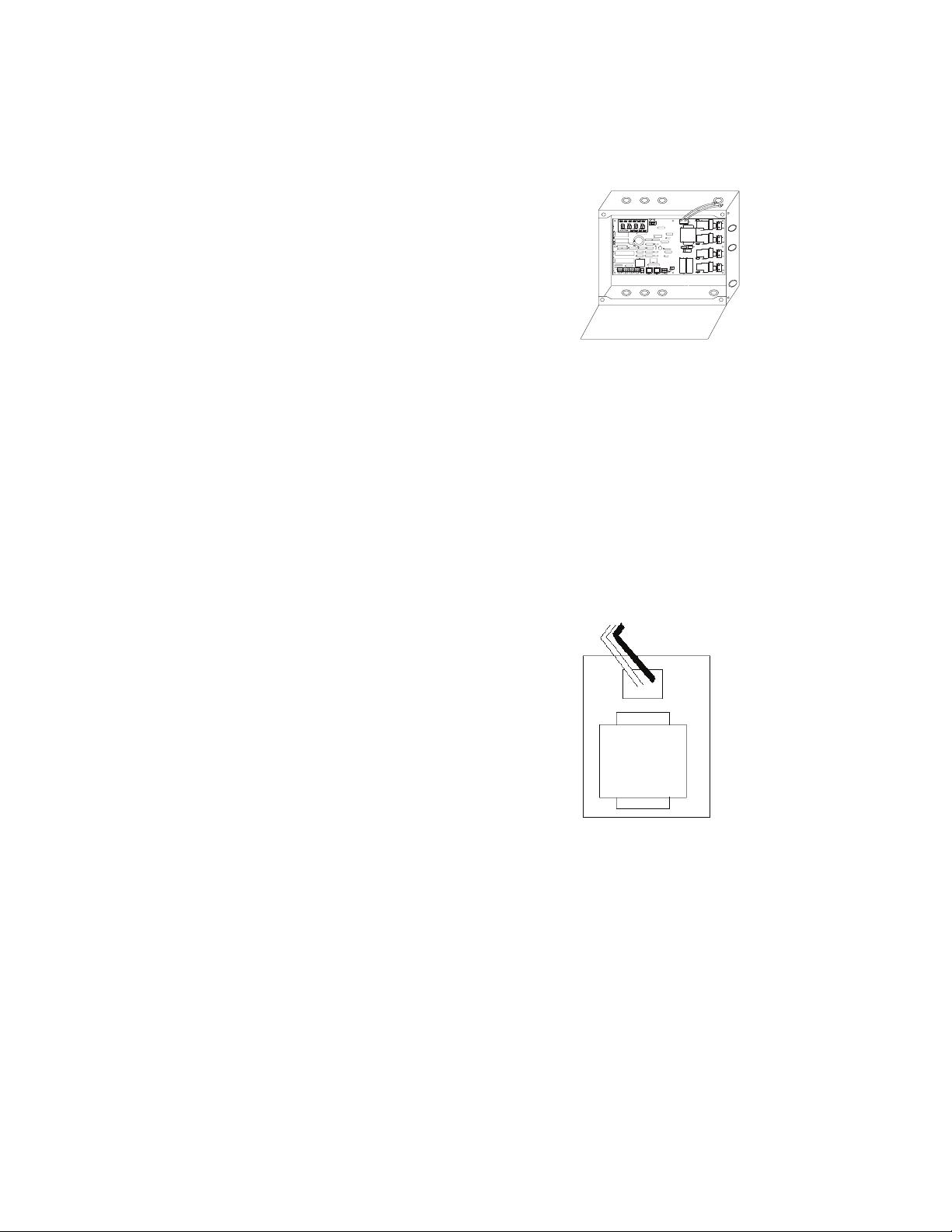
Mounting the Cabinet
1. Choose a dry location on a firm surface convenient to
the circuits being controlled. Allow full clearance for
the door of the enclosure to open fully.
2. Mount the ControlKeeper 4 cabinet using the
holes provided in the back of the enclosure. It is
recommended that the panel be mounted vertically.
3. All line voltage conductors must enter the cabinet on
the right side of the enclosure.
4. All low voltage conductors must enter the cabinet on
the left side of the enclosure.
5. Remove all debris and metal shavings from
the enclosure before applying power to the
ControlKeeper 4.
Bring low voltage in
through the Left Side
of the Enclosure
Figure 1. ControlKeeper 4 Enclosure
Bring high voltage in
through the Right Side
of the Enclosure
Power Supply Wiring
The ControlKeeper 4 is factory configured with either
a 120V or a 277V transformer. Transformer voltages are
color coded. It is recommended that a dedicated branch
circuit with circuit protection be used for power supply
wiring.
1. Connect neutral wire to the white wire.
2. If the transformer is a 277V model, connect orange
wire to a 277V circuit. If the transformer is a 120V
model, connect black wire to a 120V circuit.
Page 2
General Information
Netural=White
Netural=White
Line=120V (Black)
277 (Orange)
Netural=White
120V Transformer
Line=Black
277V Transformer
Line=Orange
Figure 2. ControlKeeper 4 Enclosure
Connecting Relay Loads
1. Test branch circuits for short circuits prior to connecting
and energizing the ControlKeeper 4.
2. Relay terminal blocks have a maximum limit of 10 AWG
wire.
3. Relays are rated for single-pole circuit use. Connection
of 2 pole circuits/loads to the ControlKeeper 4 will void
the equipment warranty.
4. Connect a 120 or 277 volt, 20 amp maximum,
de-energized branch circuit breaker to the relay terminal
block position labeled LINE.
5. Connect the load to the output terminal block position
labeled LOAD.
6. Tighten down relay terminal screws. Manufacturer’s
recommended torque rating is 7 lbs-in. (0.59 lbs-foot)
(0.8Nm).
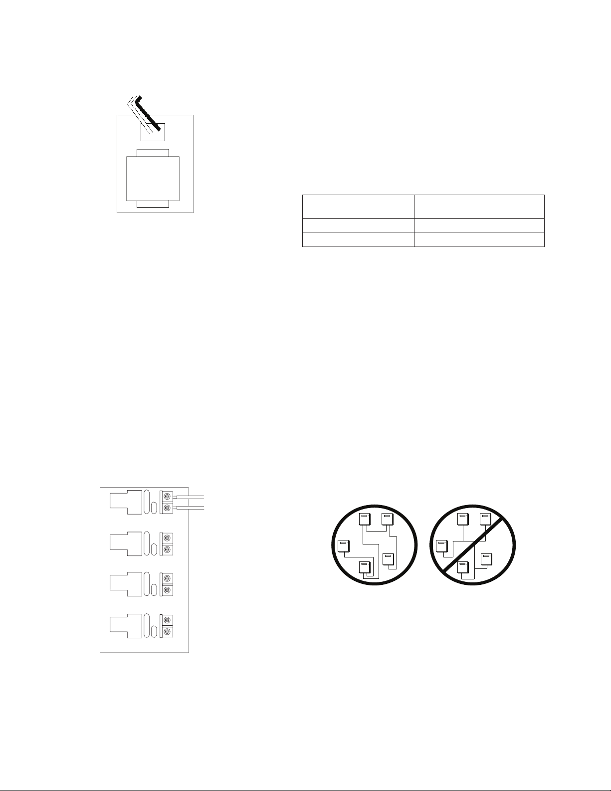
Relay Wiring
Wire: 10 AWG Max
Relay Rating: 20 amps, 277V
RELAY 1
LINE
LOAD
LINE
From Branch Circuit
To Lighting Load
Network Wiring Notes
The ControlKeeper 4 is designed to communicate with
other ControlKeeper network panels using a lighting control
RS-485 network for communications. This allows the panels
to share information and to be programmed from one
central location by a computer with the Keeper Enterprise
Software.
Please refer to Table 1 for information on recommended
wiring for network.
Acceptable
Network Wiring
Standard RS485 Belden 9841 (Shield is not used)
Plenum RS485 Belden 89841 (Shield is not used)
Table 1. Network Wiring Recommendations
For best network performance, one of the suggested
cables should be used. If the specified cable is not
used and communications problems occur that require
troubleshooting assistance, additional charges for support
may be assessed.
1. All low voltage wiring is Class 2.
2. All low voltage wiring must enter the cabinet from the
left side of the enclosure.
3. All low voltage wiring must be run in separate conduit
from line voltage wiring.
4. Test all network wiring for shorts to AC ground before
connecting to the ControlKeeper 4 panel.
5. If using Belden 9841 or 89841, leave all shields
disconnected making certain that shield is not exposed.
6. Panels and devices on the RS-485 lighting network
should be daisy-chained. Do not create a Star or
T-Tapped configuration.
Suggested Cable
LOAD
RELAY 2
LINE
LOAD
RELAY 3
LINE
RELAY 4
LOAD
Figure 3. Address Switch Information
ote:N Neutrals terminate within the adjoining lighting panel.
2
ControlKeeper 4
7. Total network length should not exceed 4000 feet.
Network Wiring Details
1. Before wiring, select the two panels that are going to
be the end panels of the network and plan a wiring
scheme accordingly. Panels should be daisy-chained,
not Star or T-Tapped.
2. Starting at one of the end panels, connect the network
(+) and (-) terminals to the next panel’s network (+) and
(-) terminals. Continue this process through the network
Page 3
making certain to observe polarity. When finished, the
two end panels will have a single pair of wires coming
into the network terminal block while all middle panels
in the network will have two sets of wires.
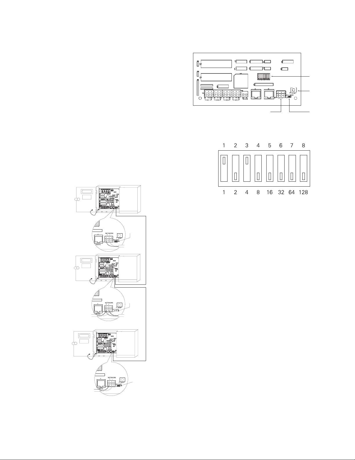
3. Set the network termination jumpers. On the end
panels on the network set to the terminated position.
For all panels in the middle of the network, remove
the network termination jumper. See Figures 4 & 5 for
details.
4. On the two end panels in the network, set the network
termination jumpers to the terminated position.
5. On the middle panels in the network, remove the
network termination jumpers.
6. Set all panel addresses using the panel network
identification DIP Switches on each panel. See Figures
5 & 6 for location and details.
7. Using the panel reset switch, issue a soft reset to each
panel to initialize the panel address. See Figure 5 for
location of the reset switch.
General Information
RS232 DIGITA NETWORK
Network Wiring
Terminal Block
Figure 5. Item Reference for Network Details
Switch
Position
Value
Network
Address
Switch
Panel
Reset
Switch
Network
Termination
Jumper
ON
OFF
End Panel
Network Wiring
Detail
Middle Panel
Network Wiring
Detail
End Panel
Network Wiring
Detail
Figure 4. Network Wiring Detail
Termination
Jumper ON
Termination
Jumper OFF
Termination
Jumper ON
All panels must be assigned a unique Network Address in order
to communicate over the lighting network. Switch positions are
labeled 1 through 8 and are valued at 1 through 128 as shown
above. The network address is calculated by adding the value of
the switch positions that are in the ON position. In the example
above, switches 1 and 3 are ON giving the panel the network
address of 5. Addresses 1 through 254 are valid addresses. Zero
and 255 are reserved for system use. To initialize the network
address with the controller, press the panel reset button after the
address is set.
Figure 6. Address Switch Information
Connecting Low Voltage Inputs
The ControlKeeper 4 logic board can support both dry
contact closure and Digital Switch inputs. If a combination
of contact input switches and Digital Switches are being
used, the combined total cannot exceed 64 inputs.
Regardless of input type used, it is recommended that
all input wiring be done prior to applying power to the
logic board or at the very least with the terminal blocks
removed from the logic board. Please verify that there are
no shorts to AC Ground prior to connection of input devices.
Regardless of input type, the following notes apply.
1. All low voltage wiring is Class 2 wiring.
2. All low voltage wiring must enter the cabinet into the
Low voltage section of the enclosure. Low voltage
wiring can be brought into the enclosure from the left
side of the enclosure. Failure to separate high voltage
from low voltage wiring may cause interference with
logic board function.
3. All low voltage wiring must be run in separate conduit
from line voltage wiring.
4. Test all low voltage wiring for shorts to AC ground
before connection to the relay panel.
ControlKeeper 4
3
Page 4
General Information
5. When powering peripheral devices such as motion
sensors and photosensors from the ControlKeeper
4 panel, there may be a limitation on the number of
sensors that can be supported. This is also true if
Digital Switches are used with the system. See the
recommendations below or contact Cooper Controls for
further information.
6. It is recommended that the terminal blocks be removed
from the board or power removed from the logic board
when doing initial switch input wiring.
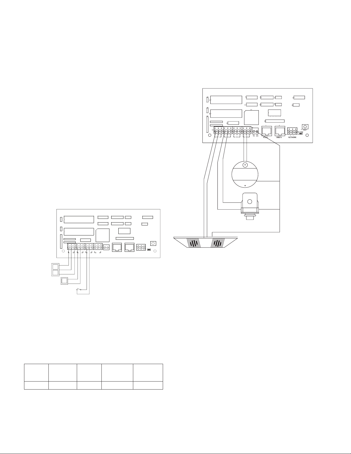
Contact Input Switch Wiring
This section describes the wiring for dry contact closure
devices. There are four switch input wiring terminals on the
left side of the ControlKeeper 4 to allow for wiring of the
dry contact closure devices.
1. Use 18 AWG twisted, unshielded wire for all low
voltage dry contact closure device wiring.
2. Maximum length for dry contact closure device wiring
is 1000 feet.
3. Please see wiring detail below for details on
connections of different devices to the
ControlKeeper 4 system.
Momentary Switch
(3 wire)
Toggle Switch (2 wire)
C20
U21
C26
U26
RN1
TB4
ON
+24VDC
OFF
Maintaned Switch (2 wire)
+24
OFFON
CH1
ON
+24VDC
ON +24
+24VDC
CH2
U17
U18
U19
U24
U23
U22
U27
41235687
U29
ON +24
ON +24
OFF
OFF
CH4
CH3
ON
U28
TB5
+24
OFF
VDCDCGND
U20
U25
J2J1
S7
RESET
NET TERM
TB7
J3
-+
NETWORKDIGITARS232
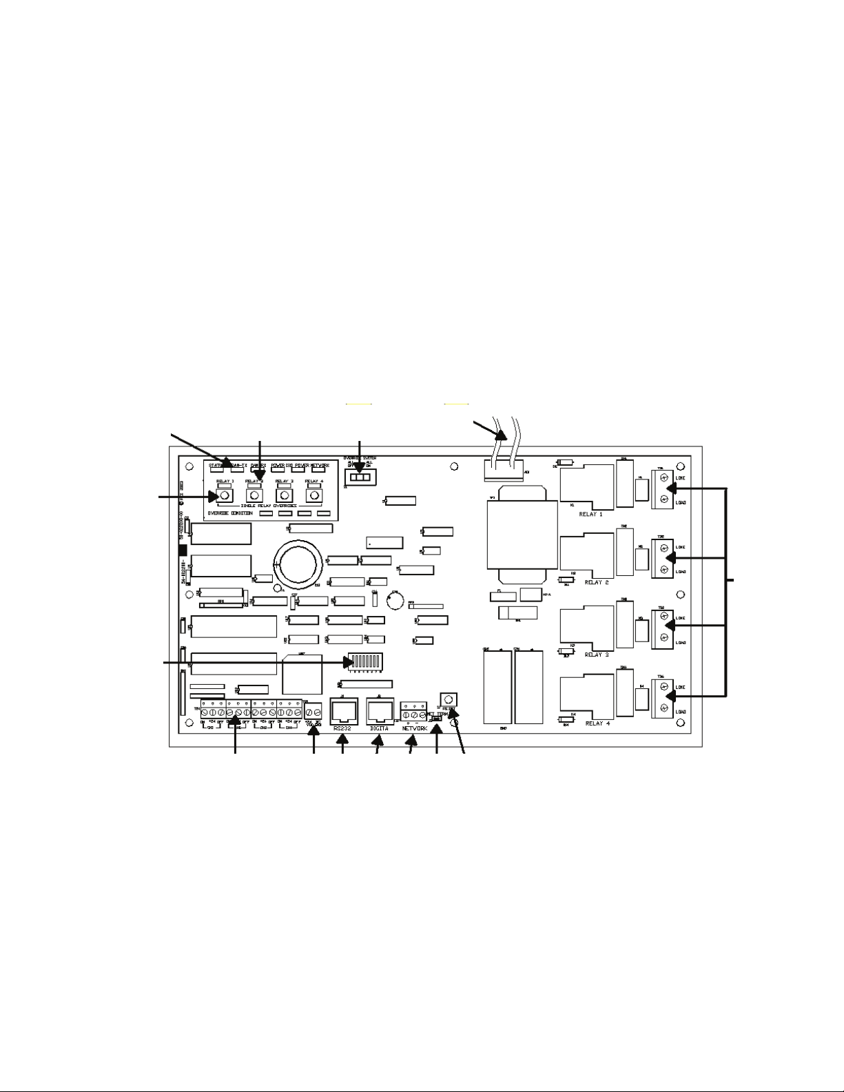
Figure 7. Standard Relay Card Wiring
Contact Input Photosensor and Greengate
Sensor Note
It is possible to use a contact input photosensor and
Greengate Motion Sensors in conjunction with the lighting
control system. The ControlKeeper 4 is capable of powering
a number of these devices. Please refer to the chart below
for details on how many devices the transformer can
support.
Greengate
PIR Sensor
Greengate
Dual-Technol
Greengate
Ultrasonic
Sensor
PPS-4
Indoor
Photosensor
40 16 20 20 4
Please contact technical support if it is necessary to power
PPS-5
Outdoor
Photosensor
additional sensors beyond the numbers listed above. These
figures do not account for additional devices such as Digital
Switches being used. If using a combination of devices,
please contact technical support for exact details on how
many devices the logic panel can power.
Black
ON
+24VDC
(Red Wire)
Yellow & White
Wires Not Used
PPS4
Black
PPS5
Black
Black
Typical Greengate
iW kcalB(
er
)
DNG CD RWP MER
Contact Input
Photosensor
Wiring
ON
(Blue
Wire)
(White Wire)
+24VDC
(Red Wire)
(Blue Wire)
+24VDC
(Red Wire)
ON
Motion Sensor
Wiring
Figure 8. Photosensor and Motion Sensor Wiring
Digital Switch Wiring
Each ControlKeeper 4 panel is capable of supporting up to 7
Digital Switch device stations and 1 GDS-I gateway device
(the number the controller is able to support is dependent
on the number of other low voltage devices wired that
require power from our logic board. Please contact Technical
Support for exact details of how many devices your logic
board can power.)
Digital Switch cable type should be Eaton’s Cooper LC
Cable, Belden 1502R (non-plenum), or Belden 1502P
(plenum).
For best network performance, one of the suggested cables
should be used. If the specified cable is not used
and communications problems occur that require
troubleshooting assistance, additional charges for support
may be assessed.
Digital Switches do not wire directly to the ControlKeeper 4
panel, but are wired to a CAN Bus network that connects to
the ControlKeeper 4 through a GDS-I device. Digital Switch
devices should be networked together in a daisy-chain
4
ControlKeeper 4
Page 5
General Information
Individual Relay
Override Switches
Hardware Override Switch
ControlKeeper® 4 Upper Left Corner
configuration. No T-Taps/Stars should be used. The GDS-I
device should reside somewhere within the daisy-chain
switch net work. Total daisy-chain network length should not
exceed 1000 feet.
The following instructions describe the GDS-I device
connection to the ControlKeeper 4. Please refer to the
Digital Switch Installation Instructions for information on
wiring the Digital Switch network to the GDS-I.
1. Mount the GDS-I next to the ControlKeeper 4 panel.
A six foot phone style cable has been provided for
connectionto the ControlKeeper 4 panel.
2. Run a length of the Digital Switch LC or Belden cabling
from the GDS-I location to the low voltage section of
the ControlKeeper 4.
3. Connect the RED wire in the cable to the +V terminal
on the back of the GDS-I and to the ControlKeeper 4 at
one of the switch input +24VDC terminals.
4. Connect the BLACK wire in the cable to the GND
terminal on the back of the GDS-I and to the
ControlKeeper 4 remote power connector GND
terminal.
5. Tape back or cap the blue and white wires and shield
wire for the cable. They will not be used for connection
between the GDS-I and lighting controller.
6. Locate the 6 foot phone style cable included in the
GDS-I box. Run this from the GDS-I into the low voltage
section of the ControlKeeper 4 enclosure plugging the
end with 9 pin head into the GDS-I. Plug the end the
RJ11 phone style plug into the ControlKeeper 4.
Applying Power
1. After wiring is complete, make certain to clean panel
of all wire clippings and fragments ensuring that no
fragments get lodged between the circuit board and
enclosure.
2. Ensure that there are no loose wires or exposed wires
that could short out.
3. Make certain that the line voltage section of the
enclosure is closed and secure.
4. Power-up the unit. It is recommended that the unit be
cleared of all programming unless the unit has been
sent pre-programmed to you by the factory. To perform
this step, hold down the reset button for about
15 seconds.
5. Please refer to the operation section of this instruction
for information on turning ON and OFF lighting loads.
Refer to the Keeper Enterprise Software manual
for information regarding the programming of the
ControlKeeper 4 jumper.
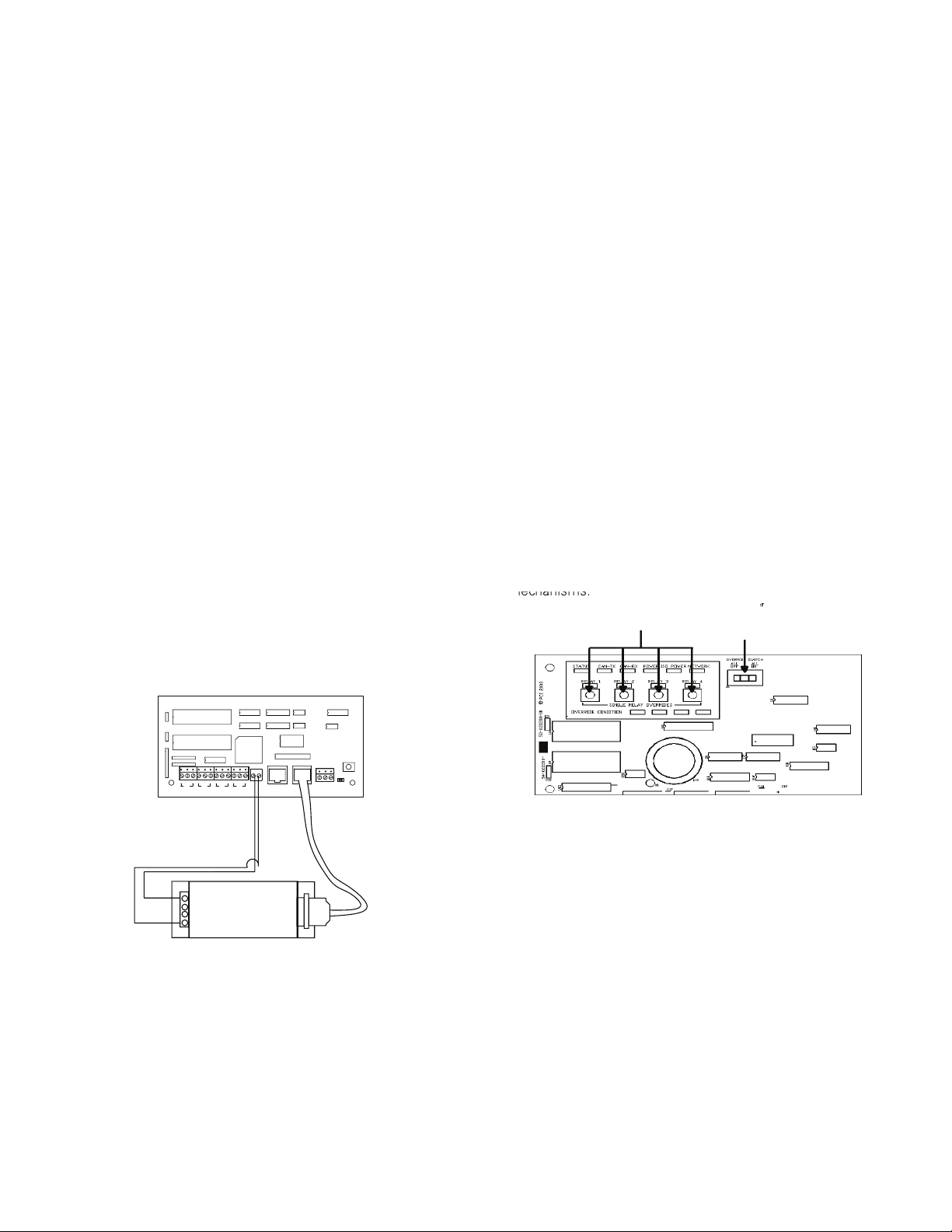
Relay Override Operation
The ControlKeeper 4 has two means of override located
on the logic board: individual relay override buttons and a
hardware override switch. It is possible to control lighting
loads and override programming using these override
mechanisms.
C20
U21
C26
U26
RN1
U29
TB4
+24
ON +24
OFFON
CH2
CH1
BLACK Wire From GDS-I
GND to CK4 GND
RED Wire From GDS-I V
+ to CK4 +24VDC
Cabling is Eaton’s Cooper LC Cable,
Belden 1502R, or Belden 1502P
Figure 9. GDS-I Wiring Detail
U17
U18
U23
U22
U27
U28
TB5
ON +24
ON +24
OFF
OFF
OFF
+24
VDCDCGND
CH4
CH3
U20
U19
U24
U25
41235687
J2J1
S7
RESET
NET TERM
TB7
J3
-+
NETWORKRS232
Wire Phone Style Cable to
RJ11 Jack on CK4 and to GDS-I
Figure 10. ControlKeeper 4 Status LEDs
Individual Relay Override Notes
Each relay on the ControlKeeper 4 may be overridden using
the individual relay override switches located at the top
GDS-I
left of the low voltage section. See Figure 9 for location
of these switches. These override switches will toggle the
associated relay’s state with each push of the button. This
type of over ride is temporary in that the override will last
until the next command that the relay is given.
Hardware Override Switch Notes
In addition to the individual relay override switches, there
is a hardware override switch that allows the override of
all relays on the board. If this switch is moved to the ALL
ON or ALL OFF position, all four relays will remain ON or
OFF as long as the switch is in that ALL ON or ALL OFF
position. The ON or OFF state is maintained regardless of
programmed state. In order for relays to run programmed
ControlKeeper 4
5
Page 6
General Information
scheduling the hardware override switch must be in the
AUTO or center position. See Figure 9 for location of the
hardware override switch.
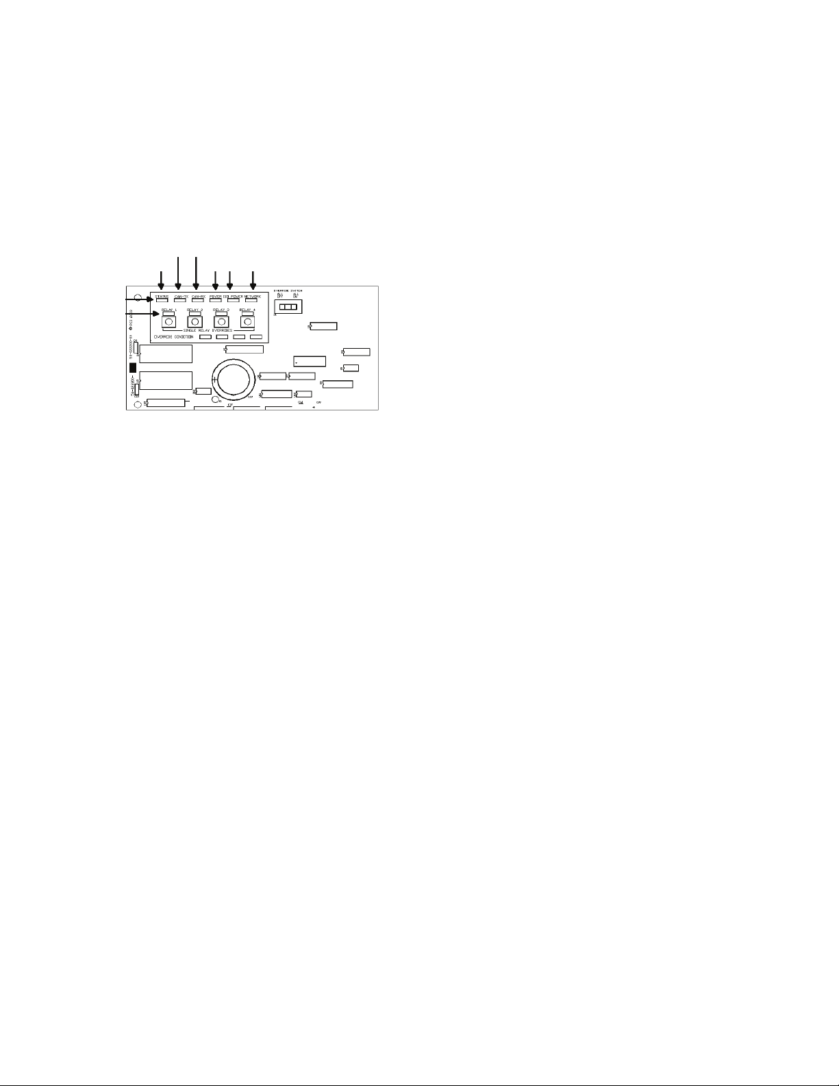
LED Operation
The ControlKeeper 4 has LEDs for status monitoring. They
consist of System Status LEDs and Relay Status LEDs.
ControlKeeper® 4 Upper Left Corner
Digita Switch
Status Power Network
System Status LEDs
Relay Status LEDs
Relay 1 Through 4
Figure 11. ControlKeeper 4 Status LEDs
System Status LEDs
There are six (6) system status LEDs that are located in the
upper left corner of the ControlKeeper 4. Please refer to
Figure 10 for location of these status LEDs. These status
LEDs will indicate proper operation or potential problems
with the ControlKeeper 4. Normal Operation includes the
following LED states.
Status LED:
The Status LED will flash ON and OFF continuously
under normal operation. The LED is an indication of
microprocessor health. If the LED is ON or OFF all the time,
please use the soft reset button on the controller. If the LED
does not resume normal flashing state, contact Technical
Support.
Digital Switch LEDs:
These LEDs, labeled CAN-TX and CAN-RX, will flash when
Digital Switch information is being passed back and forth
between the Digital Switch Gateway and the ControlKeeper
4.
Power LEDs:
These LEDs, labeled POWER and ISO POWER, indicate that
the ControlKeeper 4 is getting the proper expected voltage
from the transformer. If one or both of these LEDs is not lit,
there is a problem with power to the board. Please contact
Technical Support for further details.
Network LED:
The Network LED should flash only when activity is present
on the network wire. If communications commands are not
being transmitted over the network wire from the Keeper
Enterprise Software or broadcast switches and this LED
is flickering, ON constant, or flashing, it is an indication of
noise on the network wire that may interfere with proper
system operation. Please check all network wiring carefully
for shorts to AC Ground if this condition exists. Contact
Technical Support for further troubleshooting help.
Relay Status LEDs
There are four relay status LEDs, one for each of the
relays on the ControlKeeper 4. Please refer to Figure 10
for location of these LEDs. The relay status LEDs are an
indication of whether the associated relay is energized or
de-energized. If the relay LED is ON, the relay load should
be ON. If the relay LED is OFF, the relay load should be OFF.
ControlKeeper 4 RS232 Port
The ControlKeeper 4 has an on board RS232 port for
communications to peripheral accessory devices or to
the Keeper Enterprise Software. This RJ style jack should
not be connected to any device not intended for use with
the lighting control system. Connection to a phone line
will cause damage to the lighting control system that is
not covered under warranty. Please use only Greengate
approved device connections for connection to this port.
System Reset and Clear Commands
Under certain circumstances, you may want to reset the
ControlKeeper 4. There are two different types of reset
commands available in the ControlKeeper 4 system: a soft
reset command and a clear reset command.
Soft Reset Command:
A soft reset command is used to initialize a new
panel address with the panel. It can also be used as a
troubleshooting technique if the panel is not responding or
to free up the microprocessor if the unit’s STATUS LED is
not flashing. The Soft Reset Command will not cause loss
of panel programming. To perform a Soft Reset Command,
press in and then immediately release the reset button in
the lower right corner of the logic panel. When the reset
button is pressed and released, the status LED may hesitate
briefly then resume normal operation.
Clear Settings Command:
A clear settings command is used to remove all
programming from a ControlKeeper 4 unit. It should be
done before downloading programming to the unit for
the first time or when asked to by a Technical Support
representative. Please use caution with this command!
When performing a Clear command, all relay loads will turn
OFF. Use the Hardware Override Switch to keep lighting ON
if necessary.
In order to reprogram the unit, you will need to use the
Keeper Enterprise Software. To perform a Clear Command,
press and hold down the reset button in the lower right
corner of the low voltage section for a period of 15 seconds
6
ControlKeeper 4
Page 7
General Information
until the STATUS LED turns OFF. Once the STATUS LED
turns OFF, release the reset button. The ControlKeeper 4
unit will be reset back to factory default settings.
Programming the ControlKeeper 4
The ControlKeeper 4 is programmed using Keeper
Enterprise Software. Please refer to the Keeper Enterprise
Manual for programming details. It is recommended that a
Clear Command be performed on the controller before the
first programming download to clear any test data that may
be left in the controller from factory testing.
Item Reference
The ControlKeeper 4 consists of a logic board with a clear
separation of line-voltage and low voltage components.
There are several features of note on the logic board as
pointed out in the below item reference diagram.
2
3
4
1
Repair Information
If a repair becomes necessary on your ControlKeeper 4 unit,
please refer all service to Greengate’s technical support line
at 1-800-553-3879. The ControlKeeper 4 contains no user
serviceable parts.
5
14
Figure 12. Item Reference
1. Individual Relay Override Switches (Temporary override)
2. System Status LEDs
3. Relay Status LEDs
4. Panel Hardware Override Switch (ALL OFF, AUTO, ALL
ON)
5. Transformer Wiring Leads: White = Neutral,
Orange = 277V, Black = 120V
6. Relay Wiring Terminals
6
78910111213
7. Panel Reset Switch
8. Network Terminator Jumper
9. Network Wiring Terminal Block
10. Digital Switch Port
11. Panel Communications Port
12. Peripheral Power Terminal: +24 VDC, DC Ground
13. Switch Input Wiring Channels
14. Panel Network Address DIP Switches
ControlKeeper 4
7
Page 8
Renseignements généraux
Renseignements généraux
Le modèle ControlKeeper 4 est livré en une seule boîte et
est doté d’un transformateur soit de 120V soit de 277V.
Il est configuré en usine et est muni de relais normalement
ouverts. Pour connaître le type de modèle en votre
possession, consultez votre commande.
Pour commencer
1. Ne jetez pas ces instructions d’installation. Veuillez les
conserver pour une référence ultérieure.
2. Débranchez toujours toutes les alimentations
électriques avant de procéder au câblage.
3. Utilisez uniquement aux fins prévues et à la tension
indiquée.
4. L’installation, les réparations et l’entretien doivent être
effectués par des techniciens en entretien et réparation
ou par du personnel qualifié.
5. L’installation doit se faire conformément au Code
national de l’électricité et à tout autre code applicable.
6. Les renseignements sur l’installation et le câblage qui
sont fournis dans ce document sont fondés sur des
normes et des pratiques reconnues dans l’industrie.
Si ces instructions vont à l’encontre de codes ou de
règlements applicables, veuillez communiquer avec
Greengate avant de commencer l’installation.
7. Une haute tension est présente dans le boîtier. Prenez
des précautions extrêmes lorsque vous effectuez
l’entretien de cet équipement. Le non-respect de cet
avertissement et des procédures de sécurité
appropriées peut entraîner des blessures sérieuses
ou la mort et/ des dommages à l’équipement.
8. Pour vous aider à configurer et à programmer les
dispositifs par la suite, prenez en note l’emplacement
de ces derniers et des connexions.
Faire passer les ls à basse
tension par le côté gauche
du boîtier
Faire passer les ls à haute
tension par le côté droit du
boîtier
Figure 1. Boîtier du ControlKeeper 4
Câblage de l’alimentation
Le modèle ControlKeeper 4, configuré en usine, est doté
d’un transformateur de 120V ou de 277V. Les tensions du
transformateur sont codées par couleur. Il est conseillé de
réserver un circuit de dérivation avec protection des circuits
à l’utilisation du câblage du bloc d’alimentation.
1. Connectez le câble neutre au câble blanc.
2. Si le transformateur de votre appareil est de 277V,
brachez le fil orange à un circuit de 277V. Si le
transformateur de votre appareil est de 120V, branchez
le fil noir à un circuit de 120V.
Ligne = 120V (noir),
277 (Orange)
Neutre=blanc
Montage de l’armoire électrique
1. Choisissez un endroit sec sur une surface dure, proche
des circuits à commander. Prévoyez un dégagement
suffisant pour l’ouverture complète de la porte.
2. Montez l’armoire ControlKeeper 4A à l’aide des trous
ménagés au dos du boîtier. Il est recommandé
d’assembler le panneau à la verticale.
3. Tous les conducteurs à haute tension doivent pénétrer
dans l’armoire par le côté droit du boîtier.
4. Tous les conducteurs à basse tension doivent pénétrer
dans l’armoire par le côté gauche du boîtier.
5. Dégagez tous les débris et les rognures de métal du
boîtier avant de mettre le ControlKeeper 4 sous tension.
8
ControlKeeper 4
120V Transformateur
Ligne=noir
Neutre=blanc
277V Transformateur
Ligne=Orange
Neutre=blanc
Figure 2. Boîtier du ControlKeeper 4
Branchement des charges du relais
1. Effectuez un essai des circuits de dérivation pour
des courts-circuits avant de brancher et de mettre le
ControlKeeper 4 sous tension.
2. Les borniers des relais ont une limite maximum de
3. 10 AWG pour le câblage.
4. Les relais sont destinés à être utilisés avec les
circuits unipolaires seulement. Le branchement
du ControlKeeper 4 à des circuits ou des charges
bipolaires annulera la garantie de l’appareil.
Page 9

Renseignements généraux
Câblage des relais
5. Branchez un disjoncteur de dérivation hors tension de
120 ou 277 volts, 20A maximum à l’emplacement étiqu
té LINE du bornier du relais.
6. Branchez le câble de charge à l’emplacement étiqueté
LOAD du bornier de sortie.
7. Serrez les vis du bornier des relais. La classification
ducouple recommandée est de 0,8Nm
(7lb-po ou 0,59lb-pi).
Câble: 10 AWG max.
Classification du relais: 20 A, 277V
RELAIS 1
RELAIS 2
RELAIS 3
RELAIS 4
LIGNE
CHARGE
LIGNE
CHARGE
LIGNE
CHARGE
LIGNE
CHARGE
Du circuit de dérivation
Vers la charge d’éclairage
Pour la meilleure performance réseau, utilisez un des câbles
suggérés. Si vous n’utilisez pas le câble spécifié et que des
problèmes de communication nécessitant une assistance
au dépannage se présentent,des frais additionnels pour le
soutien pourraient être exigés.
1. Tout le câblage à basse tension est de classe 2.
2. Tout le câblage à basse tension doit entrer dans
l’armoire en passant par le côté gauche du boîtier.
3. Tout le câblage à basse tension doit passer dans un
conduit séparé du câblage à tension composée.
4. Avant de connecter le panneau ControlKeeper 4A,
vérifiez qu’il n’y a aucun risque de court-circuit à la
masse dans le câblage réseau.
5. Si vous utilisez le câble Belden 9841 ou le 89841, ne
branchez pas les écrans de blindage et assurez-vous
qu’ils ne soient pas exposés.
6. Les panneaux et les dispositifs du réseau d’éclairage
RS-485 devraient être configurés
Remarques concernant le câblage réseau
Le ControlKeeper 4 est conçu pour communiquer avec
d’autres panneaux ControlKeeper en réseau grâce
à un réseau de régulation d’éclairage RS-485 pour
les communictions. Cela permet aux panneaux de
partagerde l’information et d’être programmés à partir
d’un emplacement central au moyen d’un ordinateur et du
logiciel Keeper Enterprise. Veuillez vous référer au tableau
1 pour obtenir de l’information sur le câblage réseau
recommandé.
Figure 3. Interrupteur d’adresse
emarque:R Les fils neutres se terminent à l’intérieur du
panneau d’éclairage adjoint.
Acceptable
Câblage réseau
Câble suggéré
Norme RS485 Belden 9841(Écran non utilisé)
Plenum RS485 Belden 89841 (Écran non utilisé)
Tabla 1. Recommandations de câblage réseau
7. La longueur totale du réseau ne doit pas dépasser
1219 m (4000 pi).
Détails sur le câblage du réseau
1. Avant de procéder au câblage, sélectionnez deux
panneaux qui vous serviront depanneaux d’extrémité
de réseau et planifiez votre schéma de câblage en
conséquence. Les panneaux devraient être configurés
en série, et non en étoile ou en T.
2. À partir d’un des panneaux d’extrémité, connectez le
réseau (+) et les bornes (-) au réseau (+) et aux bornes
(-). Répétez ce processus pour tout le réseau en vous
assurant de bien respecter la polarité. Lorsque vous
avez terminé, les deux panneaux d’extrémité devraient
avoir une seule paire de câbles entrant dans le bornier
du réseau tandis que tous les panneaux du milieu
devraient avoir deux ensembles de câbles.
3. Paramétrez les bretelles de fin de réseau. Sur les
panneaux d’extrémité de réseau, réglez-les à la position
finale. Pour ce qui est des panneaux de milieu de
réseau, enlever les bretelles de fin de réseau. Voir les
figures 4 et 5 pour plus de détails.
4. Sur les panneaux d’extrémité de réseau, réglez les
bretelles de fin de réseau à la position finale.
5. Pour ce qui est des panneaux de milieu de réseau,
enlever les bretelles de fin de réseau.
ControlKeeper 4
9
Page 10

Renseignements généraux
Position de
6. Configurez toutes les adresses des panneaux à l’aide
des interrupteurs DIP d’identification de réseause
trouvant sur chaque panneau. voir l’emplacement et les
détails aux figures 6 et 7.
7. Au moyen de l’interrupteur de réinitialisation, effectuez
une réinitialisation logicielle pour chacun des panneaux
en vue d’initialiser l’adresse de chaque panneau.
Voir figure 5 pour l’emplacement de l’interrupteur de
réinitialisation.
Détail du
câblage des
panneaux
d'extrémité
du réseau
Détail du
câblage des
panneaux
intermédiaires
du réseau
Détail du
câblage des
panneaux
d'extrémité
du réseau
Figure 4. Câblage réseau
RS232 DIGITA NETWORK
Bornier de
câblage réseau
Figure 5. Composants utilisés dans le réseau
Cavalier de
terminaison
ouvert
Cavalier de
terminaison
fermé
Cavalier de
terminaison
ouvert
Commutateurs
d'adresses
réseau
Commutateur
de réinitialisation
du panneau
Bretelle de
terminaison
de réseau
l'interrupteur
ON
OFF
Valeur
Pour communiquer dans le réseau d’éclairage, tous les panneaux doivent
posséder une adresse de réseau unique. Comme illustré ci-dessus, les
commutateurs sont associés à des numéros de position allant de 1 à 8 et
des valeurs allant de 1 à 128. La valeur réseau correspond à l’addition des
valeurs de position des commutateurs qui sont dans la position ON. Dans
l’exemple ci-dessus, les commutateurs 1 et 3 sont sur ON, ce qui donne une
valeur réseau (adresse) de 5. Les adresses peuvent aller de 1 à 254. Les
nombres 0 et 255 sont réservés à l’usage du système. Pour initialiser
l’adresse réseau depuis le contrôleur, appuyez sur le bouton de réinitialisation du panneau une fois l’adresse configurée.
Figure 6. Interrupteur d’adresse
Branchement des entrées de basse tension
La carte électronique de logique du ControlKeeper 4 peut
supporter les dispositifs de fermeture à contact sec et
les entrées à interrupteurs numériques. Si vous utilisez
une combinaison d’interrupteurs d’entrée par contact et
d’interrupteurs numériques, le nombre total d’entrées ne
peut excéder 64.
Peu importe le type d’entrée utilisé, il est recommandé que
tout le câblage d’entrée soit effectué avant de mettre la
carte de logique sous tension ou du moins que les borniers
soient enlevées de la carte de logique. Avant de connecter
les di positifs d’entrée, vérifiez qu’il n’y a aucun. risque de
court-circuit à la masse dans le câblage réseau Peu importe
le type d’entrée utilisé, veuillez prendre en considération la
remarque suivante.
1. Tout le câblage à basse tension est de classe 2.
2. Tout le câblage à basse tension doit entrer dans
l’armoire dans la section « basse tension » du boîtier.
Tout le câblage à basse tension peut passer par le
côté gauche du boîtier. Si vous ne séparez pas les
câbles à basse tension des câbles à haute tension, il
est possible que cela cause des interférences avec les
fonctions de la carte logique.
3. Tout le câblage à basse tension doit passer dans un
conduit séparé du câblage à tension composée.
4. Avant d’effectuer la connexion au panneau de relais,
vérifiez tout le câblage à basse tension en vue de vous
assurer qu’il n’y a aucun risque de court-circuit à la
masse dans le câblage réseau.
5. Lorsque vous alimentez du matériel périphérique,
par exemple des détecteurs de mouvements et des
photodétecteurs, à partir du panneau ControlKeeper
4, il est possible que seulement un nombre limité de
détecteurs soient supportés. C’est aussi le cas pour
les interrupteurs numériques utilisés avec le système.
Référez-vous aux recommandations ci-dessous ou
communiquez avec Cooper Controls pour obtenir plus
d’information.
10
ControlKeeper 4
Page 11

Renseignements généraux
6. Il est recommandé d’enlever tous les borniers de la
carte électronique ou de couper le courant de la carte
de logique lorsque vous procédez au câblage des
entrées à interrupteurs initial.
Câblage des interrupteurs d’entrée par contact
Cette section décrit le câblage pour les dispositifs de
fermeture à contact sec. Il y a quatre bornes de câblage
pour les commutateurs d’entrée sur la partie gauche du
LiteKeeper-4 pour permettre le câblage des dispositifs de
fermeture à contact sec.
1. Utilisez des fils torsadés et non blindés 18 AWG pour le
câblage de dispositifs de fermeture à contact sec et
bassetension.
2. La longueur maximum pour un câble d’un dispositif de
fermeture à contact sec est 305 m (1000 pi).
3. Veuillez consulter les détails de câblage ci-dessous pour
plus d’information concernant les différents dispositifs
du système ControlKeeper 4.
C20
U21
C26
U26
RN1
TB4
ON
(2 Fils)
+24 V C.C.
OFF
Interrupteur
Instantané (3 Fils)
Interrupteur à bascule
Interrupteur à contact maintenu (2 Fils)
+24
OFFON
CH1
ON
+24 V C.C.
ON +24
+24 V C.C.
U17
U18
U19
U20
U24
U23
U22
U27
U29
ON +24
ON +24
OFF
OFF
CH3
CH2
ON
U28
TB5
+24
OFF
VDCDCGND
CH4
41235687
U25
J2J1
S7
RESET
NET TERM
TB7
J3
-+
NETWORKDIGITARS232
Figure 7. Câblage pour la carte de relais standard
Remarque concernant les capteurs d’entrée
photodtecteur et Greengate
Il est possible d’utiliser des capteurs d’entrée photodtecteur
et Greengate conjointement avec le système de contrôle
d’éclairage. Le ControlKeeper 4 est capable d’alimenter
plusieurs de ces dispositifs. Veuillez consulter le tableau
ci-dessous pour les détails sur le nombre de dispositifs po
vant être supporté par le transformateur.
Détecteur
IRP
Greengate
Détecteur
double
technologie
Détecteur
ultrasonique
Greengate
PPS-4
Photodétecteur
intérieur
Greengate
40 16 20 20 4
Veuillez communiquer avec le service d’assistance
technique si vous devez alimenter plus de détecteurs
que les quantités indiquées ci-dessus. Ces figures ne
tiennent pas compte des dispositifs additionnels tels que
les interrupteurs numériques utilisés. Si vous utilisez une
combinaison de dispositifs, veuillez communiquer avec le
PPS-5 Extérieur
Photodétecteur
service d’assistance technique pour les détails exacts sur
le nombre de dispositifs que le panneau de logique peut
alimenter.
Noir
+24 V c.c.
ON (Fil
ON (Fil bleu)
ON (Fil blanc)
+24 V c.c.
bleu)
+24 V c.c.
PPS4
Fils jaune et
blanc non utilisés
Noir
PPS5
Noir
Noir
Câblage typique des détecteurs
de mouvements Greengate
REM ALIMENTATION
DC DE TERRE (Fil noir)
Câblage de
l’entrée de
photodétection
de contact
Figure 8. Câblage du photodétecteur et du détecteur
de mouvements
Câblage d’interrupteur numérique
Chaque panneau ControlKeeper 4 peut supporter jusqu’à
7 stations de dispositifs pour interrupteurs numériques et
1 dispositif GDS-I (le nombre supporté par le régulateur
dépend de la quantité des autres dispositifs à basse
tension câblés nécessitant de l’énergie provenant de la
carte de logique. Veuillez communiquer avec le service de
l’assistance technique pour les détails exacts concernant
le nombre de dispositifs que le tableau de logique peut
alimenter.)
Le type de câble pour interrupteurs numériques utilisé
devrait être le Eaton’s Cooper LC, le Belden 1502R (nonplénum) ou le Belden 1502P (plénum).
Pour la meilleure performance réseau, utilisez un des câbles
suggérés. Si vous n’utilisez pas le câble spécifié et que des
problèmes de communication nécessitant une assistance
au dépannage se présentent, des frais additionnels pour le
soutien pourraient être exigés.
Les interrupteurs numériques ne sont pas reliés
directement au panneau du ControlKeeper 4,mais plutôt à
un bus CAN qui, lui, est relié au ControlKeeper®4, par un
dispositif GDS-I. Les interrupteurs numériques devraient
être en étoile ou en T. Aucune prise en T ou étoile ne devrait
être utilisée. Le dispositif GDS-I devrait être placé quelque
part dans le réseau d’interrupteurs configurés en série. La
longueur maximale du réseau en série ne doit pas dépasser
304,8 m (1000 pi).
ControlKeeper 4
11
Page 12

Renseignements généraux
Les instructions suivantes expliquent comment connecter
le dispositif GDS-I au ControlKeeper 4. Veuillez vous référer
aux instructions d’installation des interrupteurs numériques
pour obtenir de l’information sur le raccordement du réseau
d’interrupteurs numériques au dispositif GDS-I.
1. Montez le GDS-I près du panneau ControlKeeper 4.
Un câble de type fil de téléphone compris permet le
raccordement du réseau au panneau ControlKeeper 4.
2. Faites passer une partie du câble LC ou Belden pour
interrupteurs numériques de l’emplacement du
GDS-I et jusqu’à la section «basse tension» du
ControlKeeper-4MD.
3. Raccordez le fil ROUGE du câble à la borne +V située à
l’arrière du GDS-I et à une des bornes de l’entrée à
interrupteur+24 VDC du ControlKeeper 4.
4. Raccordez le fil NOIR du câble à la borne de MISE À
LA TERRE au dos du GDS-I et à la borne de MISE À LA
TERRE du connecteur d’alimentation à distance
ControlKeeper-T.
5. Mettez du ruban adhésif ou bouchez les fils bleu et
blanc ainsi que les fils blindés du câble. Ils ne seront
pas utilisés pour le raccordement entre le GDS-I et le
régulateur d’éclairage.
6. Repérez le câble de type fil de téléphone de 1,8m
(6 pi) compris dans la boîte GDS-1. Ce fil doit partir
du GDS-I et atteindre la section « basse tension» du
boîtier du ControlKeeper 4; branchez l’extrémité dotée
de 9 broches de raccordement au GDS-I. Raccordez
l’extrémité du fil de type fil de téléphone RJ11 au
ControlKeeper 4.
C20
U21
C26
U26
RN1
TB4
+24
CH1
Fil NOIR de GDS-I
GND à CK4 GND
Fil ROUGE de GDS-I V+ à
CK4 +24 V c.c.
U17
U18
U23
U22
U27
U29
ON +24
ON +24
OFF
OFFON
CH3
CH2
U28
TB5
ON +24
OFF
OFF
+24
VDCDCGND
CH4
U20
U19
U24
U25
41235687
J2J1
S7
RESET
NET TERM
TB7
J3
-+
NETWORKRS232
Branchez le câble téléphonique
au connecteur femelle
RJ11 à CKT et au GDS-I
Appliquer l’alimentation
1. Une fois le raccordement terminé, assurez-vous de
libérer le panneau de tout morceaux ou fragments de fil
en vue qu’aucun fragment ne se loge entre la carte de
circuits imprimés et les boîtiers.
2. Assurez-vous qu’il n’y a pas de fils lâches ou exposés
qui pourraient causer un court-circuit.
3. Assurez-vous que la section « tension composée » du
boîtier est fermée et sécurisée
4. Mettez l’appareil sous tension. Il est recommandé de
supprimer toute programmation de l’unité, à moins
que l’unité vous ait été livrée préprogrammée en
usine. Pour réaliser ces étapes,Maintenez le bouton de
réinitialisation enfoncé pendant environ 15 secondes.
5. Veuillez vous référer à la section liée à l’exploitation
contenue dans les présentes instructions pour obtenir
de l’information sur la manière d’allumer ou d’éteindre
les charges d’éclairage. Consultez le manuel de
l’utilisateur du logiciel Keeper Enterprise pour obtenir
de l’information concernant la programmation du
ControlKeeper 4 Bretelle.
Relayer des opérations de priorité
Le ControlKeeper 4 est doté de deux functions de priorité
sur la carte électronique: Des boutons prioritaires de relais
individuels et un interrupteur prioritaire. Il est possible
de régler les charges d’éclairage et d’outrepasser la
programmation en utilisant les mécanismes de priorité.
Coin gauche supérieur du ControlKeeper® 4
Interrupteur d'annulation
de relais individuels
Figure 10. DEL d’état du ControlKeeper 4
Interrupteur prioritaire
Notes de prise en charge de relais individuel
GDS-I
Les câbles sont des câbles Eaton’s Cooper
LC, Belden 1502R, ou Belden 1502P
Figure 9. Câblage du GDS-I
Chaque relais sur le ControlKeeper 4 peut être outrepa sé
en utilisant les interrupteurs prioritaires de relais individuels
situés dans le coin supérieur gauche de la section
«basse tension». Voir figure 9 pour l’emplacement de ces
interrupteurs. Ces interrupteurs de priorité changeront
l’état du relais associé à chaque pression du bouton.
Cette annulation est temporaire; elle est active jusqu’à la
prochaine commande transmise au relais.
Notes concernant l’interrupteur prioritaire du matériel
En plus des interrupteurs prioritaires de relais individuels,
il existe un interrupteur prioritaire du matériel qui permet
la prise en charge de tous les relais sur le tableau. Si
l’interrupteur est placé en position ALL ON ou ALL OFF,
tous les relais restent ouverts ou fermés aussi longtemps
12
ControlKeeper 4
Page 13

Renseignements généraux
que l’interrupteur est en position ALL ON ou ALL OFF. L’état
ON ou OFF est maintenu peu importe l’état programmé.
Pour que les relais suivent l’ordonnancement prévu,
l’interrupteur prioritaire doit être en position AUTO ou en
position centrale. La Figure 9 vous permet de localiser
l’interrupteur d’annulation.
Opération DEL
Le ControlKeeper 4 est équipé de DEL permettant de
surveiller son fonctionnement. En effet, il est constitué de
DEL indiquant l’état du système et de DEL indiquant l’état
des relais.
Coin gauche supérieur du ControlKeeper® 4
Interrupteur numérique
État Alimentation Réseau
DEL d’état du
système
DEL d’état des
relais Relais 1 à 4
Figure 11. DEL d’état du ControlKeeper 4
DEL d’état du système
Il y a six (6) systèmes de statut DEL qui se trouvent dans
le coin supérieur gauche du ControlKeeper 4. Consultez
la Figure 10 pour connaître l’emplacement de ces statuts
DEL. Ces statuts DEL indiquent le bon fonctionnement
et les problèmes potentiels liés au ControlKeeper 4. Un
ftionnement normal comprend les statuts DEL suivants:
Statut DEL:
Dans des conditions normales, les DEL de statut clignotent
de façon continue. Les DEL constituent une indication de la
santé du microprocesseur. Si la DEL est allumée ou éteinte
en tout temps, utilisez le bouton de réinitialisation logicielle
qui se trouve sur le régulateur. Si la DEL ne recommence
pas à clignoter normalement, communiquez avec le Soutien
technique.
Interrupteur numérique DEL:
Ces DEL, étiquetées CAN-TX et CAN-RX, clignotent lorsque
l’information de l’interrupteur numérique est échangée entre
la passerelle de l’interrupteur numérique et le ControlKeeper
4.
DEL d’alimentation:
Ces DEL, étiquettée POWER et ISO POWER, indiquent
que le ControlKeeper 4 reçoit la tension appropriée du
transformateur. Si un, ou les deux, DEL n’est pas allumée,
c’est qu’il y a un problème d’alimentation du panneau.
Veuillez communiquer avec le Soutien technique pour plus
de détails.
Réseau DEL:
Le Réseau DEL devrait uniquement clignoter quand
une activité est présente sur le câblage réseau. Si des
instructions de communications ne sont pas transmises
par le câblage réseau à partir du logiciel Keeper Entreprise
ou des interrupteurs de transmission et ce DEL clignote,
constamment sur ON ou flashe, c’est un indicateur qu’il
existe du bruit sur le câblage réseau susceptible d’interférer
avec la bonne opération du système. Dans ce cas, procédez
à une vérification approfondie des câbles réseau pour
détecter un court-circuit à la masse. Communiquez avec le
Soutien technique pour la résolution des problèmes.
Statut DEL de relais
Il existe quatre DEL d’état de relais, une pour chacun des
relais du ControlKeeper 4. Consultez la Figure 10 pour
connaître l’emplacement de ces DEL de statut. Les DEL
d’état de relais indiquent si le relais correspondant est sous
tension ou hors tension. Lorsque le relais est sous tension,
sa charge doit être active. Lorsque le relais est hors tension,
sa charge doit être inactive.
Port ControlKeeper-4 RS232
Le ControlKeeper 4 est équipé d’un port embarqué
RS232 pour les communications avec les périphériques
accessoires ou avec le logiciel de Keeper Enterprise. Cette
fiche RJ ne doit jamais être connectée à un périphérique
qui n’est pas destiné au système de commande d’éclairage.
Le branchement à une ligne téléphonique causera, au
système de commande d’éclairage, des dégâts qui ne sont
pas couverts par la garantie. Veuillez utiliser uniquement les
connexions de périphérique approuvées par Greengate pour
une connexion à ce port.
Commandes de réinitialisation et de suppression
du système
Dans certaines circonstances, vous devez réinitialiser le
ControlKeeper 4. Le système ControlKeeper 4 possède deux
types de commandes de réinitialisation: une réinitialisation
logicielle et une réinitialisation de suppression.
La commande de réinitialisation logicielle:
Une commande de réinitialisation logicielle est utilisée
pour initialiser une nouvelle adresse de panneau avec
le panneau. Elle peut également être utilisée comme
technique de dépannage si le panneau ne répond pas ou
bien pour libérer le microprocesseur si le STATUS LED du
dispositif ne clignote pas. La commande de réinitialisation
logicielle n’occasionne pas la perte de la programmation
panneau. Pour exécuter une commande de réinitialisation
logicielle, appuyez puis relâchez immédiatement le bouton
de réinitialisation dans le coin inférieur droit du panneau de
logique. Une fois le bouton de réinitialisation enfoncé, puis
relâché, il se peut que la DEL de statut hésite brièvement,
puis recommence à fonctionner normalement.
ControlKeeper 4
13
Page 14

Renseignements généraux
La commande de suppression des paramètres:
Une commande qui annule les réglages est utilisée pour
effacer la programmation du dispositif ControlKeeper 4. Elle
doit être effectuée avant le tout premier téléchargement
de la programmation de l’appareil, ou sur demande d’un
représenant du soutien technique. Soyez prudent quand
vous utilisez cette commande! Lorsque vous utilisez
cette commande, toutes les charges de relais seront
hors tension. Vous pouvez utiliser l’interrupteur prioritaire
matériel si vous voulez que les lumières restent allumées.
Pour reprogrammer l’appareil, vous aurez besoin du logiciel
Keeper Enterprise. Pour procéder à la commande de
suppression, appuyez sur le bouton de réinitialisation situé
dans le coin droit inférieur de la section « basse tension »
et maintenez-le enfoncé pendant 15 secondes, jusqu’à ce
que les DEL D’ÉTAT s’éteignent Une fois les DEL D’ÉTAT
éteintes, relâchez le bouton de réinitialisation. L’unité
ControlKeeper 4 sera réinitialisée selon les paramètres par
défaut réglés en usine.
2
3
4
Référence de l’item
Le ControlKeeper 4 est constitué d’une carte de logique
dotée d’une séparation transparente entre les composantes
de basse tension et celles de tension composée. Il
existe plusieurs fonctions de note comme l’indiquent le
diagramme de référence suivant.
Programmer le ControlKeeper 4
Le ControlKeeper 4A se programme à l’aide du logiciel
Keeper Enterprise. Pour en savoir davantage à ce
sujet, consultez le manuel de Keeper Enterprise. Il est
recommandé d’effectuer la commande de suppression
de paramètres sur le contrôleur avant la première
programmation afin d’effacer toutes les données provenant
des essais en usine.
Informations concernant la réparation
Si vous avez besoin d’une réparation sur votre appareil
ControlKeeper 4, veuillez communiquer avec le soutien
technique au 1-800-553-3879. L’appareil ControlKeeper 4 ne
contient aucune pièce réparable par l’utilisateur.
5
1
14
Figure 12. Schéma des pièces
1. Interrupteurs prioritaires de relais individuels
(Temporaire)
2. DEL d’état du système
3. Statut DEL de relais
4. Interrupteur d'annulation du matériel du panneau
(ALL OFF, AUTO, ALL ON)
5. Fils du transformateur: Blanc = neutre, orange = 277V,
noir = 120V
6. Bornes du câblage de relais
6
78910111213
7. Commutateur de réinitialisation du panneau
8. Bretelle de terminaison de réseau
9. Bornier de câblage réseau
10. Port d'interrupteur numérique
11. Port de communication du panneau
12. Borne d'alimentation périphérique: +24V c.c., CC terre
13. Canaux de câblage d'entrée de commutateur
14. Interrupteur d’adresse DIP du réseau de panneaux
14
ControlKeeper 4
Page 15

Información general
Información general
El modelo ControlKeeper 4 se envía en un paquete y está
configurado con un transformador de 120V o de 277V.
La configuración de fábrica tiene los relés normalmente
abiertos. Remítase a la información de su pedido para
determinar qué tipo de modelo ha adquirido.
Cómo comenzar
1. No deseche estas instrucciones de instalación.
Consérvelas para tenerlas como referencia futura y para
contar con información sobre el funcionamiento.
2. Siempre desconecte la alimentación antes de realizar el
cableado.
3. Utilice este panel únicamente con el voltaje y fin
indicados.
4. Personal calificado o técnicos en mantenimiento deben
realizar toda instalación o servicio de mantenimiento.
5. Instale de conformidad con el Código Eléctrico Nacional
y con todo otro código aplicable.
6. La información de instalación y cableado que contiene
este documento se basa en los estándares y las
prácticas aceptados en la industria. Si existiera un
conflicto entre estas instrucciones y cualquier código
u ordenanza aplicables, contacte a Greengate antes de
proceder con la instalación.
7. En el interior del alojamiento hay alto voltaje. Tome
todas las medidas de precaución posibles al realizar
el servicio de mantenimiento en este equipo. De
no seguirse esta advertencia y los procedimientos
de seguridad correspondientes, se podrían generar
lesiones graves o la muerte, o daños en el equipo.
8. Documente todas las terminaciones y ubicaciones del
cableado y del dispositivo, de modo que los dispositivos
se puedan configurar y programar correctamente para
su operación.
Haga ingresar los cables de
bajo voltaje a través del lado
izquierdo del alojamiento
Haga ingresar los cables de
alto voltaje a través del lado
derecho del alojamiento
Figura 1. Alojamiento del ControlKeeper 4
Cableado de la fuente de alimentación
El ControlKeeper 4 está configurado de fábrica con un
transformador de 120V o de 277V. Los distintos voltajes
del transformador vienen con códigos por colores. Se
recomienda incluir en el transformador un circuito de rama
dedicado, con protección de circuito, para así realizar un
cableado de alimentación adecuado.
1. Conecte el cable neutro con el cable blanco.
2. Si el transformador es un modelo de 277V, conecte el
cable naranja a un circuito de 277V. Si el transformador
es un modelo de 120V, conecte el cable negro a un
circuito de 120V.
Línea = 120V (negro)
277 (Naranja)
Neutro = Blanco
Montaje del recinto
1. Elija una ubicación seca en una superficie estable
y conveniente para los circuitos que se están
controlando. Deje un amplio espacio para que la puerta
del alojamiento se abra por completo.
2. Monte el recinto del ControlKeeper 4 usando los
orificios incluidos en la parte posterior del alojamiento.
Se recomienda montar el panel de forma vertical.
3. Todos los conductores de tensión de línea deben
ingresar al recinto desde el lado derecho del
alojamiento.
4. Todos los conductores de bajo voltaje deben ingresar al
recinto desde el lado izquierdo del alojamiento.
5. Quite todo tipo de residuos y virutas metálicas del
alojamiento antes de encender el ControlKeeper 4.
ControlKeeper 4
Transformador de 120V
Línea = Negro
Neutro = Blanco
Transformador de 277V
Línea = Naranja
Neutro = Blanco
Figura 2. Alojamiento del ControlKeeper 4
Conexión de las cargas del relé
1. Pruebe los circuitos de rama para corroborar que no se
produzcan cortocircuitos antes de conectar y energizar
el ControlKeeper 4.
2. Los bloques de terminales del relé tienen un límite
máximo de cable de 10 AWG.
3. Los relés están clasificados para el uso en circuitos
unip lares. La conexión de circuitos/cargas bipolares al
ControlKeeper 4 anulará la garantía del equipo.
15
Page 16

Información general
4. Conecte un disyuntor de circuito de rama
desenergizado de 120 o 277 voltios y 20 amperios
como máximo, a la posición del bloque de terminales
del relé etiquetada como LINE (línea).
5. Conecte la carga a la posición del bloque de terminales
de salida etiquetada como LOAD (carga).
6. Ajuste los tornillos del terminal del relé. La tasa de
torsión recomendada por el fabricante es de 7 lb/pulg.
(0,59 lb/pie) (0,8 Nm).
Cableado del relé
Cable: 10 AWG como máximo.
Características nominales del relé:
20 amperios, 277V
RELÉ 1
RELÉ 2
RELÉ 3
RELÉ 4
LÍNEA
CARGA
LÍNEA
CARGA
LÍNEA
CARGA
LÍNEA
CARGA
Del circuito de rama
Hacia la carga de iluminación
Para un mejor funcionamiento de la red, se debería utilizar
uno de los cables sugeridos. Si no se utiliza el cable
especificado y se produjeran problemas de comunicación
que requieran asistencia para la resolución de problemas, se
podrán aplicar cargos adicionales.
1. Todos los cables de bajo voltaje son cables de Clase 2.
2. Todos los cables de bajo voltaje deben ingresar al
gabinete desde el lado izquierdo del alojamiento.
3. Todos los cables de bajo voltaje deben pasar por un
conducto distinto al e los cables de tensión de línea.
4. Pruebe todos los cables de la red para verificar que no
se produzcan cortocircuitos en la conexión a tierra de
CA antes de conectarlos al panel ControlKeeper 4.
5. Si usara cables Belden 9841 o 89841, deje todas las
pantallas desconectadas,asegurándose de que no
queden expuestas.
6. Los paneles y dispositivos de la red de iluminación
RS-485 se deben conectar en serie. No cree una
configuración en estrella o de derivación en T.
Figura 3. Información del interruptor de dirección
ota:N Los neutros terminan dentro del panel de iluminación
contiguo.
Notas sobre el cableado de la red
El ControlKeeper 4 está diseñado para comunicarse con
otros paneles de red ControlKeeper utilizando una red de
control de iluminación RS-485 para las comunicaciones.
Esto permite que los paneles compartan información y que
se puedan programar desde una ubicación central utilizando
una computadora con el software Keeper Enterprise.
Consulte la Tabla-1 para obtener información sobre el
cableado recomendado para la red.
Cableado aceptable
para la red
Estándar RS485 Belden 9841 (No se usa pantalla)
Plenum RS485 Belden 89841 (No se usa pantalla
Tabla 1. Recomendaciones para el cableado de la red
Cable sugerido
7. La longitud total de la red no debe exceder los
4000 pies (1200 metros).
Detalles para el cableado de la red
1. Antes de proceder con el cableado, seleccione los dos
paneles que serán los paneles terminales de la red y
diagrame el esquema de cableado en consecuencia.
Los paneles se deben conectar en serie, no en estrella
o en derivación en T
2. Desde uno de los paneles del extremo, conecte los
terminales (+) y (-) con los terminales (+) y (-) de la red
del panel siguiente. Continúe con el proceso a través
de la red para asegurarse de conservar la polaridad.
Cuando termine, los dos paneles del extremo tendrán
un único par de cables que llegan al bloque de
terminales de la red, mientras que todos los paneles
medios en la red tendrán dos pares de cables.
3. Fije los puentes de terminación de la red. En los
paneles del extremo de la red, fije en la posición de
terminación. Para todos los paneles en el medio de la
red, quite el puente de terminación de la red. Consulte
las Figuras 4 y 5 para más detalles.
4. En los dos paneles del extremo de la red, fije los
puentes de terminación de la red en la posición de
terminación.
16
ControlKeeper 4
Page 17

punto terminal
Posición del
5. En los paneles medios de la red, quite los puentes de
terminación de la red.
6. Establezca todas las direcciones del panel usando los
interruptores DIP de identificación de la red del panel
en cada uno de los paneles. Consulte las Figuras 5 y 6
para ver la ubicación y los detalles.
7. Con el interruptor de reinicio del panel, inicie un reinicio
simple para que cada panel inicialice con la dirección
del panel. Consulte la Figura 5 para ver la ubicación del
interruptor de reinicio.
Detalle del
cableado de la
red del panel
de extremo
Detalle del
cableado
de la red del
panel medio
Detalle del
cableado de la
red del panel
de extremo
Puente
terminal
encendido
Puente
terminal
apagado
Puente
terminal
encendido
Figura 4. Detalle del cableado de la red
Interruptor
de dirección
de la red
Interruptor
de reinicio
del panel
RS232 DIGITA NETWORK
Bloque de terminales
de los cables de la red
Puente del
de la red
Información general
interruptor
ON
OFF
Valor
Todos los paneles deben tener asignada una dirección única a los
fines de comunicarse en toda la red de iluminación. Las
posiciones del interruptor vienen marcadas del 1 al 8 y tienen un
valor de 1 a 128, como se muestra arriba. La dirección de la red
se calcula sumando el valor de las posiciones del interruptor que
estén en posición de encendido. En el ejemplo anterior, los
interruptores 1 y 3 están en posición de encendido, dándole al
panel la dirección 5 de la red. Las direcciones 1 a 254 son
válidas. Cero y 255 están reservadas para uso del sistema. Para
inicializar la dirección de la red con el controlador, presione el
botón de reinicio del panel luego de establecer la dirección.
Figura 6. Información del interruptor de dirección
Conexión de las entradas de bajo voltaje
La placa lógica ControlKeeper 4 puede admitir tanto cierre
por contacto seco como entradas de interruptores digitales.
Si se utilizará una combinación de interruptores de entrada
de contacto e interruptores digitales, el total combinado
no puede superar las 64 entradas. Sin importar el tipo de
entrada que se utilice, se recomienda que todo el cableado
de entrada se realice antes de aplicar energía a la placa
lógica o,al menos, sin el bloque de terminales colocado en
la placa lógica. Verifique que no existan cortocircuitos en
el cable de conexión a tierra de CA antes de conectar los
dispositivos de entrada. Sin importar el tipo de entrada, se
aplican las siguientes notas.
1. Todos los cables de bajo voltaje son cables de Clase 2.
2. Todo el cableado de bajo voltaje debe ingresar al recinto
desde la sección de bajo voltaje del alojamiento. El
cableado de bajo voltaje se puede llevar al alojamiento
desde su lado izquierdo. Si no se separan los cables
de alto voltaje de los de alto voltaje podría haber
interferencia con el funcionamiento de la placa lógica.
3. Todos los cables de bajo voltaje deben pasar por un
conducto distinto al del cableado de tensión de línea.
4. Pruebe todos los cables de bajo voltaje para detectar
cortocircuitos en el cable de conexión a tierra de CA
antes de conectar el panel del relé.
5. Cuando aplique energía a los dispositivos periféricos,
como sensores de movimiento y fotosensores del
panel ControlKeeper 4, podría haber un límite en cuanto
al número de sensores que se admiten. También se
aplica si se utilizarán interruptores digitales con el
sistema. Consulte las recomendaciones a continuación
o comuníquese con Cooper Controls para obtener más
información.
Figura 5. Referencia de elementos de los detalles de la red
ControlKeeper 4
17
Page 18

Información general
6. Se recomienda quitar los bloques de terminales de la
placa o interrumpir la alimentación de la placa lógica
cuando realice el cableado de entrada del interruptor
por primera vez.
Cableado del interruptor de la entrada de contacto
En esta sección se describe el cableado de los dispositivos
de cierre por contacto seco. Existen cuatro terminales
de cables de entrada del interruptor en el lado izquierdo
del ControlKeeper 4 para permitir que se pueda hacer el
cableado de los dispositivos de cierre por contacto seco.
1. Use cable de 18 AWG, trenzado y sin pantalla para todo
el cableado del dispositivo de cierre por contacto seco
de bajo voltaje.
2. La longitud máxima del cableado del dispositivo de
cierre por contacto seco es de1000 pies (304 metros).
3. Consulte los detalles del cableado a continuación para
ver cómo conectar distintos dispositivos al sistema del
ControlKeeper 4.
C20
U21
C26
U26
RN1
TB4
ON +24
+24
OFFON
CH1
(2 cables)
ENCENDIDO
+24 VCC
APAGADO
ENCENDIDO
+24 VCC
ENCENDIDO
+24 VCC
Interruptor
momentáneo
(3 cables)
Interruptor conmutable
Interruptor mantenido (2 cables)
Figura 7. Cableado de la tarjeta de relé estándar
Sensor PIR
Greengate
Sensor de
tecnología
dual
Greengate
ultrasónico
Greengate
40 16 20 20 4
Es posible utilizar un fotosensor de la entrada de contacto y
sensores de movimiento Greengate junto con el sistema de
control de iluminación. El ControlKeeper 4 tiene capacidad
para alimentar varios de estos dispositivos. Remítase a
la siguiente tabla para obtener detalles sobre la cantidad
de dispositivos que puede soportar el transformador.
Comuníquese con soporte técnico si es necesario
alimentar sensores adicionales más allá de los enumerados
anteriormente. Estas cifras no tienen en cuenta dispositivos
adicionales como interruptores digitales que se estén
utilizando. Si usa una combinación de dispositivos,
comuníquese con soporte técnico para obtener detalles
precisos sobre cuántos dispositivos puede alimentar el
panel lógico.
U29
ON +24
OFF
CH2
Sensor
OFF
CH3
U17
U22
U27
TB5
ON +24
+24
OFF
VDCDCGND
CH4
de interiores
U18
U23
U28
PPS-4
Fotosensor
U19
U24
41235687
J2J1
TB7
para exteriores
U20
U25
S7
NET TERM
J3
-+
NETWORKDIGITARS232
PPS-5
Fotosensor
RESET
Negro
ENCENDIDO
(cable azul)
ENCENDIDO
(cable azul)
+24 VCC
(cable rojo)
ENCENDIDO
(cable blanco)
+24 VCC
(cable rojo)
+24 VCC
(cable rojo)
Cables amarillo y
blanco sin utilizar
Negro
Negro
)orgen elbac(
DNG CD RWP MER
Cableado del
fotosensor de la
entrada de contacto
PPS4
PPS5
Negro
Cableado de un sensor de movimiento
estándar Greengate
Figura 8. Cableado del sensor de movimiento y del
fotosensor
Cableado del interruptor digital
Cada panel ControlKeeper 4 puede admitir hasta 7
estaciones de dispositivos de interruptores digitales y
1 dispositivo de puerta de enlace GDS-I (el número que
el controlador puede admitir depende del número de
dispositivos de bajo voltaje conectados que requieran
alimentación de nuestra placa lógica. Comuníquese con
soporte técnico para obtener detalles precisos sobre
cuántos dispositivos puede alimentar su placa lógica.)
El tipo de cable del interruptor digital debe ser Cable Eaton’s
Cooper LC, Belden 1502R (no plenum) o Belden 1502P
(plenum).
Para un mejor funcionamiento de la red, se debería utilizar
uno de los cables sugeridos. Si el cable especificado no
se usa y se producen problemas de comunicación que
requieran la resolución de problemas, se podrán aplicar
cargos adicionales. Los interruptores digitales no se cablean
directamente al panel ControlKeeper 4, sino a una red CAN
Bus que se conecta al ControlKeeper 4 a través de un
dispositivo GDS-I. Los dispositivos de interruptores digitales
se deben conectar entre sí en una configuración en serie.
No se deben utilizar conectores de derivación en
T/estrella. El dispositivo GDS-I se debe ubicar en algún
punto dentro de la configuración de la red en serie. La
longitud total de la red en serie no debe superar los
1000 pies (304 metros).
18
ControlKeeper 4
Page 19

Información general
Esquina superior izquierda del ControlKeeper® 4
Las siguientes instrucciones describen la conexión
del dispositivo GDS-I al ControlKeeper 4. Consulte las
instrucciones de instalación del interruptor digital para
obtener información sobre la conexión de la red del
interruptor digital con el GDS-I.
1. Coloque el GDS-I junto al panel ControlKeeper 4. Se
incluye un cable tipo telefónico de 6 pies (1,82 m) para
conectar el panel ControlKeeper 4.
2. Extienda la totalidad del cable LC o Belden del
interruptor digital desde la ubicación del GDS-I hasta la
sección de bajo voltaje del ControlKeeper 4.
3. Conecte el cable ROJO al terminal +V en la parte
trasera del GDS-I y al ControlKeeper 4 en uno de los
terminales de +24 VCC de entrada del interruptor.
4. Conecte el cable NEGRO al terminal de conexión a
tierra en la parte trasera del GDS-I y al terminal de
conexión a tierra del conector de alimentación remota
del ControlKeeper 4.
5. Vuelva a encintar o tape los hilos blanco y azul y aísle el
hilo del cable. No se los utilizará para conectar el GDS-I
con el controlador de iluminación.
6. Ubique el cable tipo telefónico de 6 pies (1,82 m)
incluido en la caja del GDS-I. Extiéndalo desde el
GDS-I hasta la sección de bajo voltaje del alojamiento
del ControlKeeper 4 conectando el extremo con el
cabezal de 9 pines en el GDS-I. Conecte el extremo del
conector tipo telefónico RJ11 al ControlKeeper 4.
4. Encienda la unidad. Se recomienda eliminar toda la
programación de la unidad, a menos que la hayan
enviado previamente programada de fábrica. Para
realizar este paso, mantenga presionado el botón de
reinicio durante 15 segundos.
5. Consulte la sección de funcionamiento de estas
instrucciones para obtener información sobre cómo
encender y apagar las cargas de iluminación. Consulte
el manual del software Keeper Enterprise para obtener
información sobre la programación del puente del
ControlKeeper 4.
Funcionamiento de anulación del relé
EL ControlKeeper 4 tiene dos medios de anulación ubicados
en la placa lógica: botones de anulación de relé individual
y un interruptor de anulación de hardware. Es posible
controlar las cargas de iluminación y anular la programación
utilizando estos mecanismos de anulación.
Interruptores de anulación
individual de relés
Interruptor de anulación de hardware
C20
U21
C26
U26
RN1
TB4
+24
CH1
Cable NEGRO de GDS-I
a tierra al CKT a tierra
Cable ROJO de GDS-I V+ a
CK4 +24 VCC
El cableado se realiza con cables Eaton’s
Cooper LC, Belden 1502R o Belden 1502P
U17
U18
U23
U22
U27
U29
TB5
ON +24
ON +24
ON +24
OFF
OFF
OFF
OFFON
+24
VDCDCGND
CH4
CH3
CH2
GDS-I
U20
U19
U24
U25
41235687
U28
J2J1
S7
RESET
NET TERM
TB7
J3
-+
NETWORKRS232
Conecte el cable tipo
telefónico al conector
RJ11 en CK4 y al GDS-I
Figura 9. Detalle de cableado del GDS-I
Aplicación de la alimentación
1. Tras completar el cableado, asegúrese de limpiar el
panel para quitar todos los recortes y fragmentos,
asegurándose de que no quede ninguno entre la placa
de circuito y el alojamiento.
2. Asegúrese de que no queden cables sueltos o
expuestos que pudieran generar cortocircuitos.
3. Asegúrese de que la sección de tensión de línea del
alojamiento esté cerrada y segura.
Figura 10. Indicadores LED de estado del ControlKeeper
4
Notas sobre la anulación individual de relés
Es posible anular cada relé del ControlKeeper 4 utilizando
los interruptores anulación individual de relé ubicados en
la parte superior izquierda de la sección de bajo voltaje.
Consulte la Figura 9 para ver la ubicación de estos
interruptores. Estos interruptores de anulación conmutarán
los estados de relé asociados con cada pulsación del botón.
Este tipo de anulación es temporal, en el sentido de que
durará hasta que seemita el próximo comando para el relé.
Notas sobre el interruptor de anulación de hardware
Además de los interruptores de anulación individual de
relés, hay un interruptor de anulación de hardware que
permite anular todos los relés en la placa. Si este interruptor
se mueve a la posición TODOS ENCENDIDOS o TODOS
APAGADOS, los cuatro relés permanecerán encendidos o
apagados, siempre que el interruptor se encuentre en una
de estas posiciones. El estado ENCENDIDO o APAGADO
se mantiene sin importar el estado programado. Para que
los relés realicen la programación establecida, el interrtor
de anulación del hardware debe estar en la posición
AUTOMÁTICA o central. Consulte la Figura 9 para ver la
ubicación del interruptor de anulación de hardware.
ControlKeeper 4
19
Page 20

Información general
Operación del LED
El ControlKeeper-4 tiene indicadores LED para el control de
estado. Se trata de indicadores LED que indican el estado
del sistema y el estado de los relés.
Esquina superior izquierda del ControlKeeper® 4
Interruptor Digita
Estado Alimentación Red
Indicadores LED de
estado del sistema
LED de estado del
relé Relés 1 al 4
Figura 11. Indicadores LED de estado del
ControlKeeper-®4
Indicadores LED de estado del sistema
Hay seis (6) LED de estado del sistema ubicados en la
esquina superior izquierda del ControlKeeper-4. Remítase a
la Figura 10 para ver la ubicación de estos LED de estado.
Estos LED de estado indicarán el funcionamiento adecuado
o los posibles problemas con el ControlKeeper 4. El
funcionamiento normal incluye los siguientes estados
de LED.
cable de la red que puede interferir con el funcionamiento
correcto del sistema. Revise todos los cables de la red con
atención para ver que no haya cortocircuitos en el cable
de conexión a tierra de CA si se presenta esta situación.
Contacte a Soporte Técnico para obtener ayuda con la
resolución del problema.
LED de estado del relé
Hay cuatro LED indicadores del estado de los relés, uno
por cada uno de los relés en el ControlKeeper-4. Consulte
la Figura 10 para ver la ubicación de estos LED. Los LED de
estado del relé indican si el relé asociado está energizado
o no. Si el LED del relé está encendido, la carga del relé
debería estar encendida. Si el LED del relé está apagado, la
carga del relé debería estar apagada.
Puerto RS232 del ControlKeeper 4
El ControlKeeper 4 tiene un puerto RS232 incorporado para
la comunicación con los dispositivos accesorios periféricos
o con el software Keeper Enterprise. Este conector de estilo
RJ no debe conectarse con ningún dispositivo que no tenga
como fin su uso en un sistema de control de iluminación.
Su conexión a una línea telefónica generará daños en el
sistema de control de iluminación que no están cubiertos
por la garantía. Use solamente conexiones de dispositivos
aprobadas por Greengate para realizar conexiones a este
puerto.
LED de estado:
El LED de estado se encenderá y apagará continuamente
cuando se esté en el funcionamiento normal. El LED es
un indicio del buen estado del microprocesador. Si el LED
se ENCIENDE y APAGA todo el tiempo, utilice el botón
de reinicio simple en el controlador. Si el LED no vuelve al
estado normal de destellos, contacte a Soporte Técnico.
LED del interruptor digital:
Estos LED, etiquetados como CAN-TX y CAN-RX,
destellarán cuando se pase información del interruptor
digital desde y hacia la puerta de enlace del interruptor
digital y el ControlKeeper 4.
LED de alimentación:
Estos LED, que se indican como DE ALIMENTACIÓN y
ALIMENTACIÓN ISO, indican que el ControlKeeper 4 recibe
el voltaje adecuado que se espera del transformador. Si uno
o ambos LED no estuvieran encendidos, hay un problema
con la alimentación a la placa. Contacte a Soporte Técnico
para obtener más detalles.
LED de la red:
El LED de la red debería destellar solo cuando haya
actividad en el cable de la red. Si los comandos de
comunicación no se están transmitiendo por el cable de red
desde el software Keeper Enterprise o por los interruptores
de transmisión, y este LED está titilando, encendido de
manera fija o destellando, es un indicio de problemas en el
Reinicio del sistema y Comandos de reinicio total
En ciertas circunstancias, tal vez desee reiniciar el
ControlKeeper-4. Existen dos tipos diferentes de comandos
de reinicio disponibles en el sistema del ControlKeeper 4:
un comando de reinicio simple y un comando de reinicio
total.
Comando de reinicio simple:
Un comando de reinicio simple se usa para iniciar una nueva
dirección de panel con el panel. También se puede utilizar
como técnica de resolución de problemas si el panel no
responde o para liberar el microprocesador si el LED DE
ESTADO de la unidad no destella. El comando de reinicio
simple no provocará pérdidas en la programación del panel.
Para realizar un Comando de reinicio simple, presione
y suelte de inmediato el botón de reinicio ubicado en la
esquina inferior derecha del panel lógico. Cuando presiona y
suelta el botón de reinicio, el LED de estado podría destellar
brevemente antes de retomar su funcionamiento normal.
Control de configuración de eliminación:
Este control se utiliza para eliminar toda la programación de
una unidad ControlKeeper 4. Debería llevarse a cabo antes
de descargar la programación en la unidad por primera
vez o cuando así lo solicite un representante del área de
Soporte Técnico. ¡Tenga mucho cuidado con este control!
Al operar un control de eliminación, se desactivarán todas
las cargas del relé. De ser necesario, utilice el interruptor
de anulación del hardware para mantener activada la
20
ControlKeeper 4
Page 21

Información general
78910111213
iluminación. Para reprogramar la unidad, deberá utilizar el
software Keeper Enterprise. Para ejecutar un Comando de
eliminación, presione y mantenga presionado el botón de
reinicio ubicado en la esquina infrior derecha de la sección
de bajo voltaje durante unos 15 segundos hasta que se
apague el LED DE ESTADO. Una vez que se apague el
LED DE ESTADO, suelte el botón de reinicio. La unidad del
ControlKeeper 4 restaurará la configuración predeterminada
de fábrica.
Programación del ControlKeeper 4
El ControlKeeper 4 se programa utilizando el software
Keeper Enterprise. Remítase al manual del software
Keeper Enterprise para ver los detalles de programación.
Se recomienda ejecutar el Comando de eliminación en
el controlador antes de realizar la primera descarga de
programación, de modo que no quede ningún dato de
prueba en el controlador que haya surgido de la prueba en
fábrica.
2
3
4
1
Referencia de elementos
El ControlKeeper 4 consiste en una placa lógica con una
separación clara de la tensión de línea y los componentes
de bajo voltaje. Existen varias funciones para observar en la
placa lógica, como se indica en los siguientes diagramas de
referencia de elementos.
Información de reparación
En caso de que requiera una reparación de la unidad
ControlKeeper 4, comuníquese con Soporte Técnico de
Greengate llamando al 1-800-553-3879. El ControlKeeper 4
no contiene piezas que pueda reparar el usuario solo.
5
14
Figura 12. Referencia de elementos
1. Interruptores de anulación del relé individual (anulación
temporal)
2. Indicadores LED de estado del sistema
3. LED de estado del relé
4. Interruptor de anulación del hardware del panel (TODOS
APAGADOS, AUTOMÁTICO, TODOS ENCENDIDOS)
5. Terminales del cableado del transformador:
Blanco = neutro, Naranja = 277V, Negro = 120V
6. Terminales del cableado del relé
7. Interruptor de reinicio del panel
6
8. Puente del punto terminal de la red
9. Bloque de terminales de los cables de la red
10. Puerto del interruptor digital
11. Puerto de comunicaciones del panel
12. Terminal de alimentación periférico: +24 VCC, conexión
a tierra de CC
13. Canales de cableado del interruptor de entrada
14. Interruptores DIP de la dirección de red del panel
ControlKeeper 4
21
Page 22

Page 23

Page 24

WARRANTIES AND LIMITATION OF LIABILITY
Please refer to www.coopercontrol.com under the Legal section for our terms and conditions.
GARANTIES ET LIMITATIONS DE RESPONSABILITÉ LÉGALE
Veuillez consulter la section juridique de www.coopercontrol.com pour connaître nos conditions générales
GARANTÍAS Y LIMITACIONES DE RESPONSABILIDAD CIVIL
Remítase a la sección Legal del sitio web www.coopercontrol.com para conocer nuestros términos y condiciones.
Eaton
1000 Eaton Boulevard
Cleveland, OH 44122
United States
Eaton.com
Eaton’s Cooper Controls Business
203 Cooper Circle
Peachtree City, GA 30269
CooperControl.com
© 2014 Eaton
All Rights Reserved
Printed in USA
P/N: 9850-000230-01
Eaton is a registered trademark.
All trademarks are property
of their respective owners.
Eaton est une marque de commerce
déposée. Toutes les autres marques
de commerce sont la propriété de leur
propriétaire respectif.
Eaton es una marca comercial
registrada. Todas las marcas comerciales
son propiedad de sus respectivos
propietarios.
 Loading...