

Greengage ALIS Installation Manual
Version
5.1
CE and UL
www.greengage.global
PATENTED INDUCTION POWERED
TECHNOLOGY BY
Greengage
www.greengage.global/patents
Installation Manual
ALIS power, control and lighting platform
Page 1 of 27 Version 5.1 • CE and UL • ALIS Barn Lamp and ALIS Nest Lamp 1 October 2018
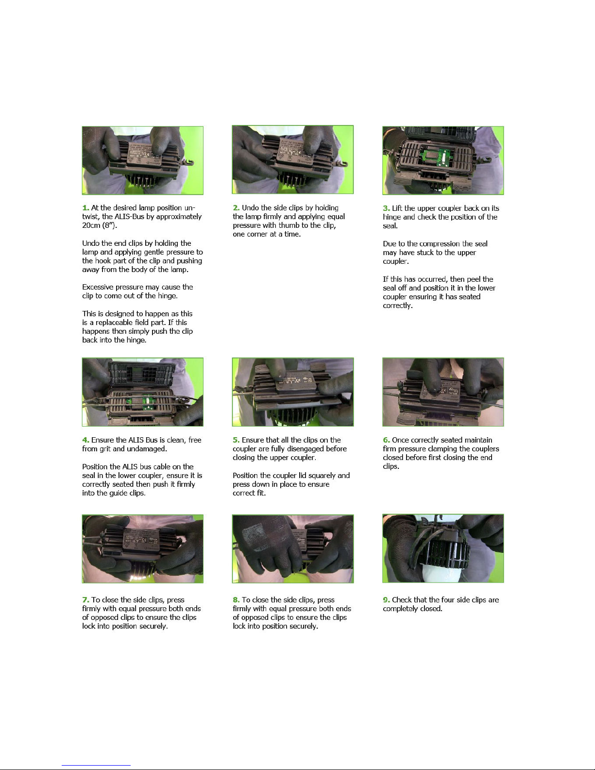
ALIS Barn Lamp best pra ctice clip on p r oc e dure

1 October 2018 Version 5 • CE and UL • ALIS Barn Lamp and ALIS Nest Lamp Page 2 of 27
Disclaimer
These instructions are provided for information purposes only.
Installation must be carried out by experienced/qualified professionals.
All electrical installation work must conform to all local and international electrical wiring and safety regulations such
as those published by CENELEC member orga nisa tions or those covered by IEC60364.
Greengage Lighting Ltd is not responsible for safety on site and installers should contact Greengage Lighting Ltd
technical support with any queries they may have at support@greengage.global
Please follow these instructions carefull y a s deviation from them may invalidate the product warranty.
Safety
Be safety conscious. Working with electrical circuits can be dangerous if you don’t take adequate safety precautions.
Always shut off the power to a circuit or device that you are working on.
Avoid wet areas when working with or on anything electrical.
If you are working on the service panel or a circuit, be s ure to place a warning label on the face of the panel. This
will warn someone not to turn on the circuit that you are working on.

Page 3 of 27 Version 5.1 • CE and UL • ALIS Barn Lamp and ALIS Nest Lamp 1 October 2018
Contents
ALIS Barn Lamp best practice clip on procedure ................................................................................................... 1
Disclaimer .......................................................................................................................................................... 2
Safety ................................................................................................................................................................ 2
Tools ................................................................................................................................................................. 4
Mounting accessories .......................................................................................................................................... 4
System description ............................................................................................................................................. 5
ALIS system components .................................................................................................................................... 5
For use only with parts as indicated ..................................................................................................................... 6
Installation procedures ....................................................................................................................................... 8
Introduction .............................................................................................................................................................................................. 8
1. Mechanical Installation.................................................................................................................................... 8
1.0 General Guidance ................................................................................................................................................................................ 8
1.1 ALIS Bus Cable Suspension .................................................................................................................................................................. 8
1.2 ALIS Power Hub Mounting .................................................................................................................................................................... 8
1.3 ALIS Dimmer Mounting ........................................................................................................................................................................ 9
2. Lamp connection ............................................................................................................................................ 9
2.1 ALIS Barn Lamp .................................................................................................................................................................................. 9
2.2 ALIS Nest Lamp ................................................................................................................................................................................. 10
3. Electrical installation ...................................................................................................................................... 11
3.0 General Guidance .............................................................................................................................................................................. 11
3.1 ALIS bus termination ......................................................................................................................................................................... 11
3.2 End termination ................................................................................................................................................................................. 12
3.3 End termination rules ......................................................................................................................................................................... 13
3.4 Hub supply cable termination (CE) ...................................................................................................................................................... 14
3.5 Hub supply cable termination (UL) ...................................................................................................................................................... 14
3.6 System Connection ............................................................................................................................................................................ 14
4. Installation checklist and system test .............................................................................................................. 15
5. Fault finding .................................................................................................................................................. 16
5.1 Led Status Indicator and Reset Button. ............................................................................................................................................... 16
5.2 Fault Finding Guide ............................................................................................................................................................................ 17
6. General points and good practi ces .................................................................................................................. 18
7. Specifications ................................................................................................................................................ 19
7.1 ALIS Power Hub electrical .................................................................................................................................................................. 19
7.2 ALIS Power Hub environmental .......................................................................................................................................................... 19
7.3 ALIS Barn Lamp ................................................................................................................................................................................ 20
7.4 ALIS Nest Lamp ................................................................................................................................................................................. 20
8. Compliance ................................................................................................................................................... 21
8.1 ALIS Power Hub 230VAC (CE) ............................................................................................................................................................ 21
8.2 ALIS Power Hub 120VAC (cULus) ....................................................................................................................................................... 21
8.3 ALIS Lamps (CE) ............................................................................................................................................................................... 22
8. 4 ALIS Lamps (cULus) ......................................................................................................................................................................... 22
Warranty validation ........................................................................................................................................... 23
Site Information ...................................................................................................................................................................................... 23
Installer Information ................................................................................................................................................................................ 23
Install Information................................................................................................................................................................................... 24
Appendix .......................................................................................................................................................... 25
Connection diagram ................................................................................................................................................................................ 25
1 October 2018 Version 5 • CE and UL • ALIS Barn Lamp and ALIS Nest Lamp Page 4 of 27
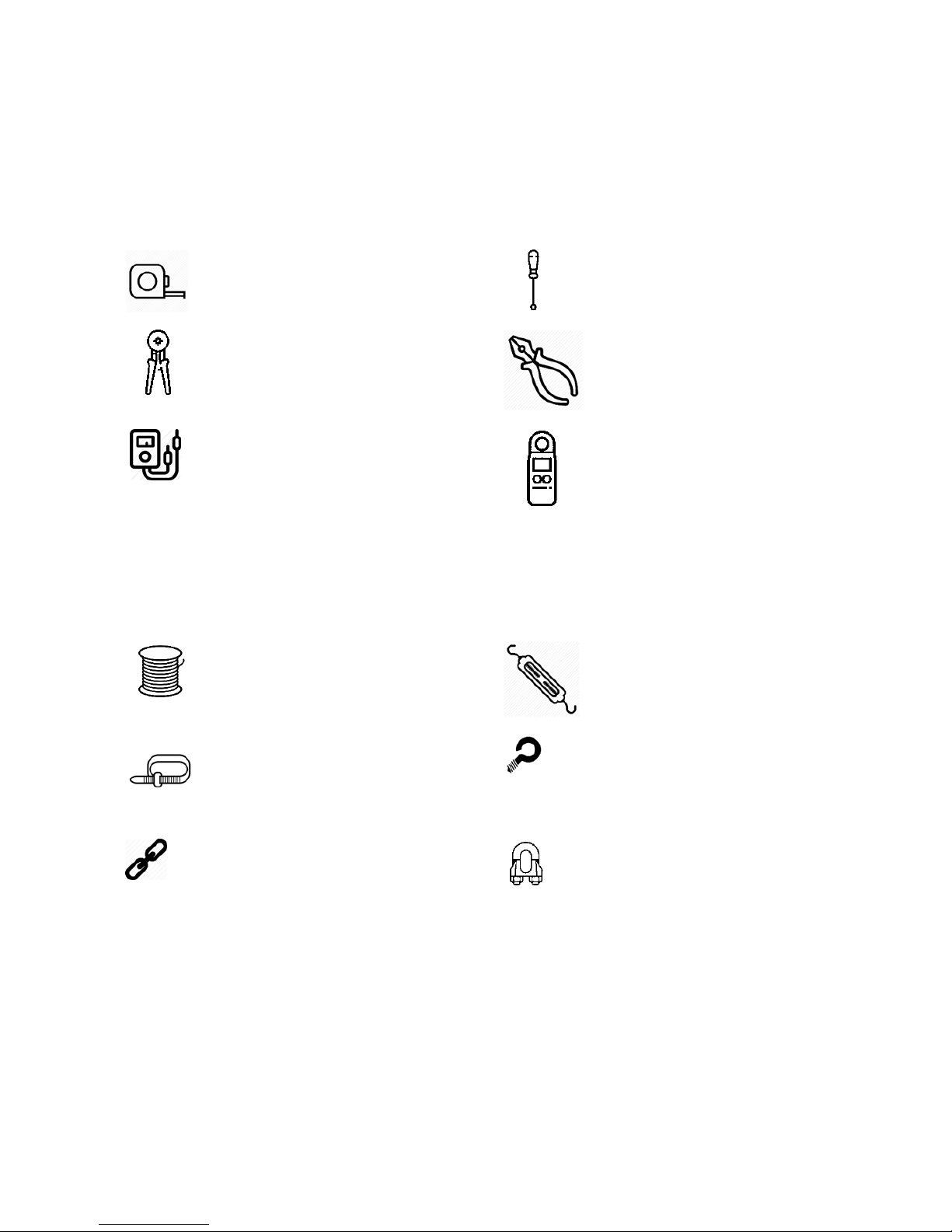
Tools
Below is a list of basic tools necessary for carrying out your installation.
Other tools may be required depending on the exact suspension, mounting method used and the composition of the
surface mounting material.
Tape Measure
Screwdrivers inc. terminal driver
Cable cutters, crimpers and wire
strippers
Pliers
Multi Meter
Light Meter
Mounting accessories
Catenary cable
Twist Buckle
Cable ties
Eye hook
Suspension chain
Wire rope clamps
Page 5 of 27 Version 5.1 • CE and UL • ALIS Barn Lamp and ALIS Nest Lamp 1 October 2018
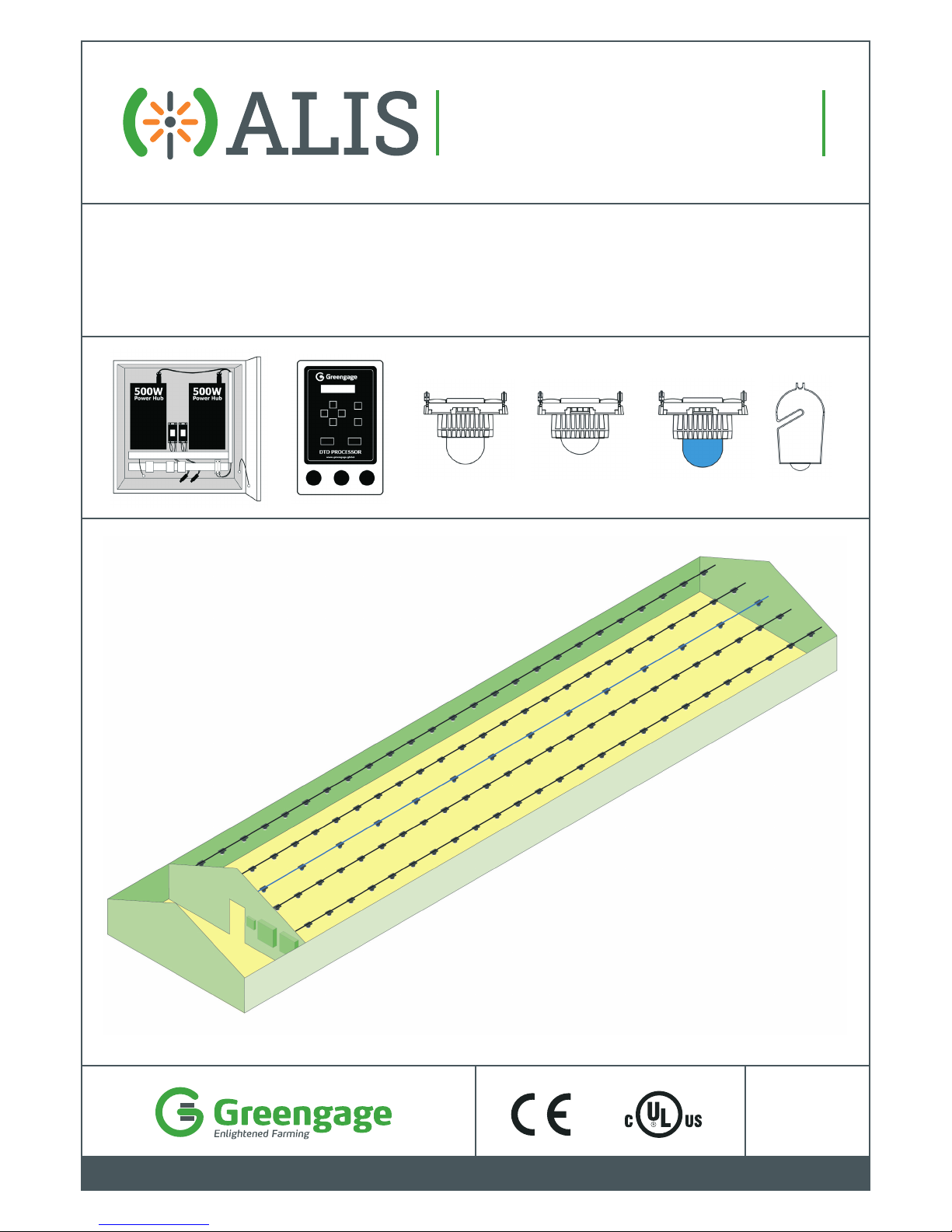
System description
The Greengage induction system (ALIS) is a 'contactless' power technology that allows LED fixtures (ALIS Lamps)
to be clipped onto the cable (ALIS Bus) without an actual physical electrical connection.
It works on the principle of distributing a highly regulated alternating current at 50 kHz along the ALIS Bus to the
ALIS lamps.
This document serves as guidance for an ALIS installation within an intensive livestock rearing building. Installers
must also follow all applicable local electrical installation standards and wiring regulations when carrying out the
installation.
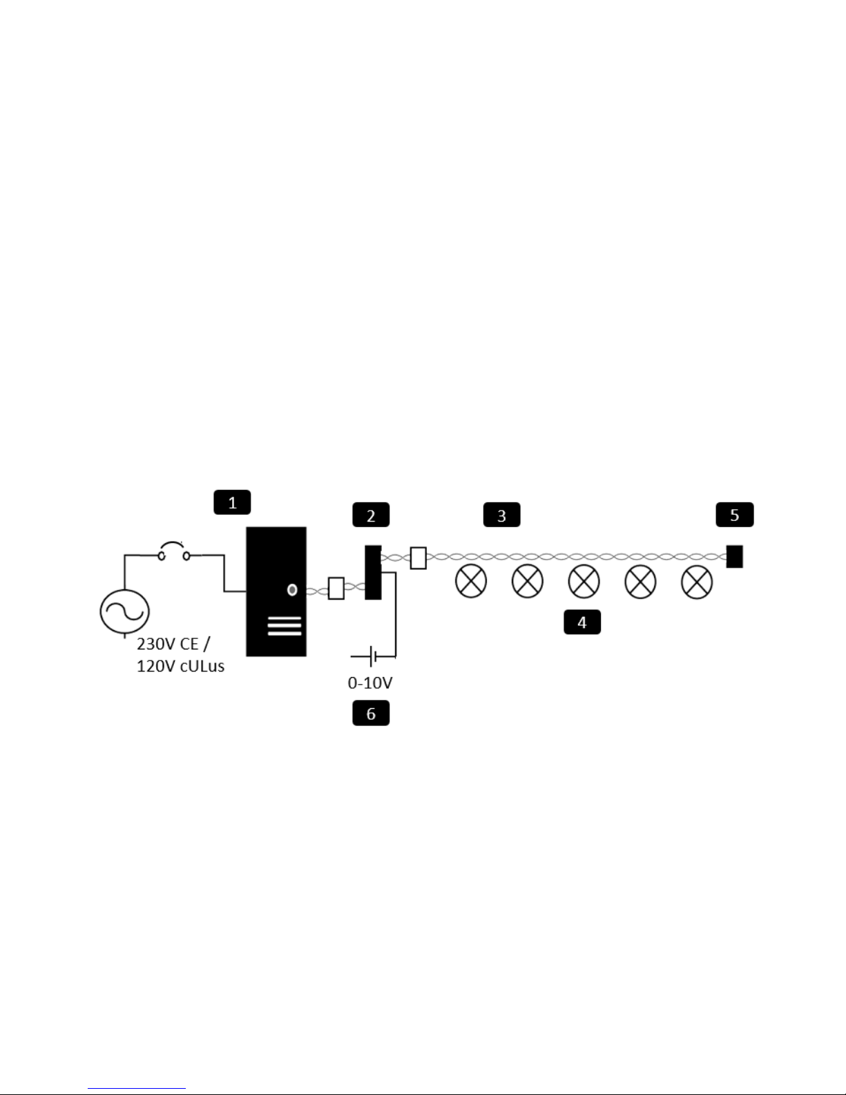
ALIS system components
ALIS is shipped as component parts for assembly on si te. There is an option to purchase a pre-configured Power
Hub panel ready for direct install.
The main components of the ALIS system are
1 ALIS Power Hub
2 ALIS Dimmer
3 ALIS Bus
4 ALIS Lamp
5 End Termination Module
6 ALIS Pot (dimmer control input)
1 October 2018 Version 5 • CE and UL • ALIS Barn Lamp and ALIS Nest Lamp Page 6 of 27
For use only with parts as indica ted
Component parts
Model
CE
Model
cULus
Additional UL
Requirements/Use
1. ALIS Power Hub
(500W)
IPH500230
IPH500110
Install only in dry
locations.
(or suitable enclosure to
meet local regulations)
2. ALIS Bus
ALS0018
(available in
500m reels)
ALS0035
(available in
1000m
reels)
Type USE-2 cable or
Type RHH-2 wire
marked VW-1.14AWG
standard type rated
90 C min and 300V
minimum.
3. ALIS Barn Lamp
Wide Beam
ALS0003
ALS0003
Suitable for wet
location use.
Do not submerse.
(IP66)
4. ALIS Barn Lamp
Narrow Beam
ALIS0001
ALIS0001
Suitable for wet
location use.
Do not submerse.
(IP66)
5. ALIS Barn Lamp
Blue
ALS0017
ALS0017
Suitable for wet
location use.
Do not submerse.
(IP66)
6. ALIS Nest Lamp
ALS0004
ALS0004
Suitable for wet
location use.
Do not submerse.
(IP69K)
7. ALIS
Potentiometer
ALS0007
ALS0007
Install only in dry
locations.
(or suitable enclosure to
meet local regulations)
Page 7 of 27 Version 5.1 • CE and UL • ALIS Barn Lamp and ALIS Nest Lamp 1 October 2018
Component parts
Model
CE
Model
cULus
Additional UL
Requirements/Use
8. ALIS Dimmer
component
ALIS Dimmer
Plastic Enclosure
Kit Assembly
ALIS Dimmer in
Plastic Enclosure
IPD1230
ALS0040
ALS0045
IPD1110
ALS0040
ALS0046
Install only in dry
locations.
(or suitable enclosure to
meet local regulations)
9. ALIS Bus End
termination
module and
enclosure
ETM
ETM
Must be housed
within a suitably
sealed enclosure
(IP66) see section
3.2
10. P2M Supply
Connector
P2M
N/A
Not applicable
CE Only
(requires suitable
enclosure to meet local
regulations)
11. ALIS IEC13 Power
to Mains
Connector
N/A
IEC13
Install only in dry
locations.
(or suitable enclosure to
meet local regulations)
12. ALIS Power Hub
Panel
ALS0006
(2 x 500W)
ALS0010
(1 x 500W)
Not
available in
North
America.
Not applicable
CE Only
13. DTD Controller
ALS0049
ALS0049
1 October 2018 Version 5 • CE and UL • ALIS Barn Lamp and ALIS Nest Lamp Page 8 of 27
Installation procedures
Introduction
This installation procedures section is divided in three parts; mechanical, lamp connect ion and electrical. These
require two distinct levels of technical competency. Here the mechanical and lamp sections are classified as semiskilled, i.e. suitable for most agricultural mechanical fitters, whilst the electrical section is classified skilled, i.e. only
suitable for competent and qualified electricians and fitters with experience and knowledge of local electrical wiring
standards and regulations.
1. Mechanical Installation
1.0 General Guidance
In this section you will find all the necessary information for the mechanical installation. This is the process
of physically fitting the components within the building. During this process no electrical connections are made.
The importance of correct mechanical fitting from the start should not be underestimated as it can be very
difficult, costly and at times impossible to correct afterwards. It is therefore worthwhile discussing the
mechanical fitting at an early stage with either the house builder or architect to ensure that correct
placement of the ALIS lamps within the house is pos sible. If not, a redesign of the lighting plan may be
required.
1.1 ALIS Bus Cable Suspension
Reference the lamp positioning information found within the lighting desig n plan. It is recommended that the ALIS
Bus cable is supported by cable ties to a catenary wire, or other carrier type, which is itself supported every three to
four metres (10 to 13 feet) and tensioned by use of a turnbuckle also ensuring that the supporting infrastructure is
sufficient to support the lamps and suspension.
As the ALIS system works inductively it is important to avoid sharp bends, returns, kinks and knots in the ALIS Bus
cable. Excess cable should be removed and certainly not be coiled or wrapped especially around metal elements.
1.2 ALIS Power Hub Mounting
The ALIS Power Hub must be mounted vertically on a metal base plate within a suitable enclosure in close proximity
to the ALIS Dimmer, away from all combustib le materials, sources of heat and out of direct sunlight. Clearances of
100mm (4 inches) from the top and bottom of the ALIS Power Hub and 75mm (3 inche s ) from the sides must be
allowed for. Please contact support@greengage.global if this is not possible.
 Loading...