

Page 1
Greenflame Eco Installation Manual
1
Installation, Operation and Servicing Instructions
Please read these instructions carefully before installing and
operating this appliance
TO BE RETAINED BY HOUSEHOLDER
Greenflame Eco
Wood Pellet Boiler 10 – 60kW
Page 2
Greenflame Eco Installation Manual
2
1. General Information:
3
1.1 Introduction:
3
1.2 Applications and Benefits of the Boiler:
3
1.3 Basic Usage Guide:
4
1.4 Users Responsibilities:
4
2. Technical Data:
4
2.1 Fuel parameters:
4
2.2 Connection of the Flue:
4
2.3 Basic Boiler Parameters:
5
2.4 Construction of the Boiler:
6
2.5 Boiler Equipment:
8
3. Setting Up and Installation of the Boiler:
9
3.1 Engineers Responsibilities:
9
3.2 Boiler Room:
9
3.3 Ventilation and Exhaust – Chimney System:
9
3.4Hydraulic and Electrical Schematics:
9 – 15
3.5 Boiler Start-up by the User:
15
3.5.1 Operating the unit:
15
3.5.2 Amount of Air, Lambda Sensor – Power Test Mode:
17
3.5.3 Air During Ignition:
17
3.5.4 Pumps:
17
3.6 Menu Language:
18
3.6.1 Start-up:
18
3.6.2 First Boiler Ignition:
18
3.6.3 Alarms and Safeguards:
18
3.6.4 Programmer Technical Data:
18
3.7 Restarting of the Boiler after Interruption caused by Lack of Fuel:
19
3.8 Final Information Regarding Installation and Boiler Start-up:
19
4. Cleaning and Maintenance of the Boiler:
19
5. Warranty and Guarantee Conditions:
19
Contents
Page 3
Greenflame Eco Installation Manual
3
1. General Information:
1.1 Introduction:
Sustainable heating solutions are at the forefront of
Trianco’s heating product portfolio. The need to increase the
awareness of alternative sources of fuel to fulfil our energy
demand has never been so great, not only to alleviate world
reliance on fossil fuels but also to encourage more natural
sources of energy supply. Trianco’s renewable portfolio
began with successful introduction of Activair air source heat
pumps, the next step naturally pointed to biomass heating
systems.
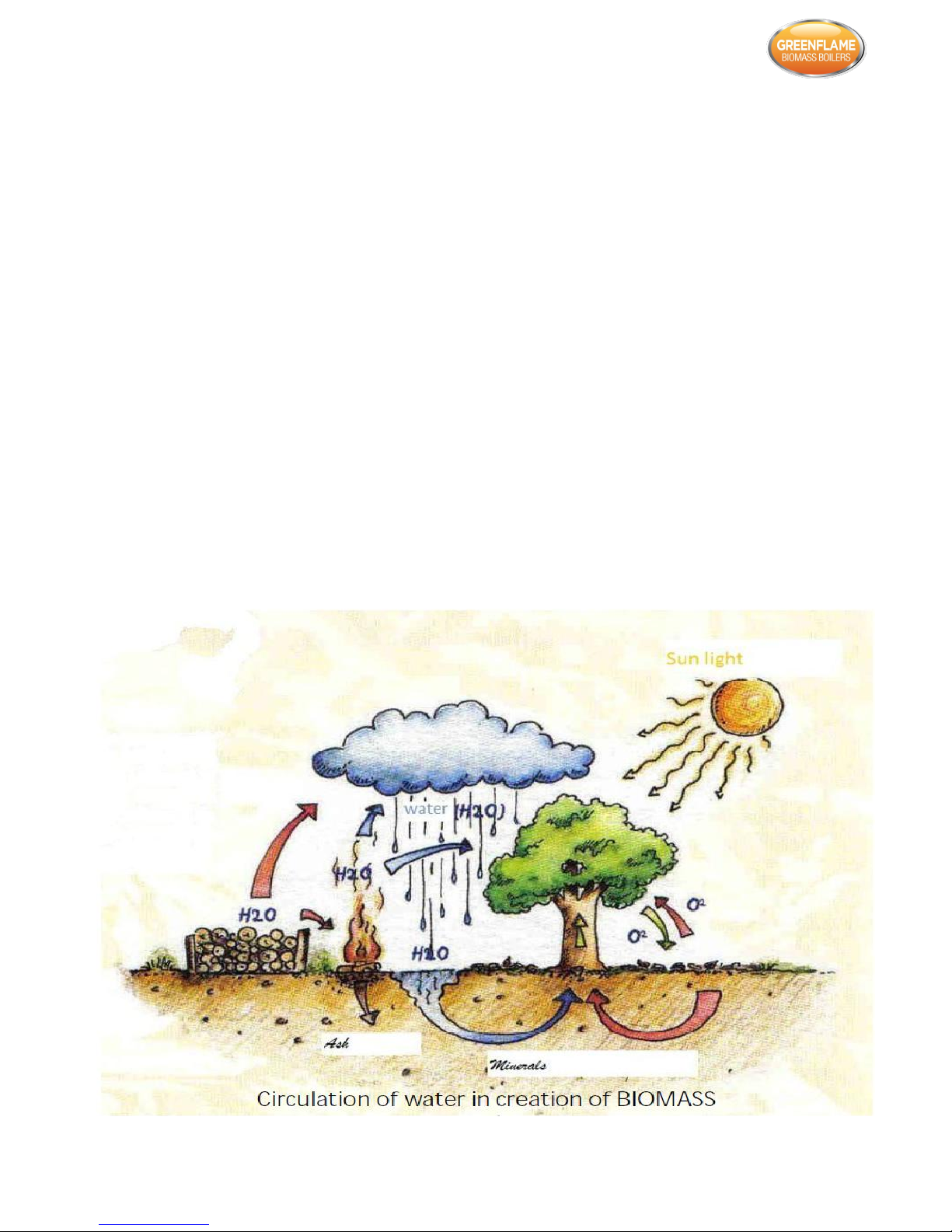
Why Biomass?
Wood is one of the most natural and sustainable fuel sources
available to us, it has a carbon neutral cycle as it releases
about the same amount of carbon dioxide into the
atmosphere through burning, as it absorbs during its growth
process.
Controlled in a very similar way to an oil or gas boiler,
Greenflame Eco biomass boilers have clean burn credentials
and super efficiencies in excess of 90%, meaning the range is
a more viable option for properties particularly in rural areas
that currently have an oil or gas heating system installed.
The Greenflame Eco is designed to burn Enplus-A1 pellets
which introduce many benefits such as:
The fuel being from a renewable source; proper
management eliminates the risk of depleting the source;
Biofuel emits only as much CO
2
that the parent material
absorbs during growth phase;
Low ash content – 0.3% - 0.5%;
Possibility to use ash as fertiliser;
Low costs involved in operation;
The cost of pellet is independent to the cost of coal;
1.2 Applications and Benefits of the Boiler:
The Greenflame Eco pellet boiler is designed for heating single
houses, detached and semi-detached houses, offices, garages,
utility buildings, etc. Some of the benefits include:
Very high efficiency that exceeds 91%, obtained by
modern, precisely tested construction;
Virtually full automation – the boiler needs to be supplied
with fuel once every couple of days, depending on
individual needs and atmospheric conditions. The start
and cease of combustion is autonomous;
Utilisation of Lambda probe, and exhaust probe on the
chimney fitting allows to obtain optimal parameters and
high combustion efficiency;
Novel cleaning system which absolves the user of the
need to clean the exchange element – all that is needed is
one general clean per year;
Low level of hazardous substance in exhaust;
Small amount of ash that can be fully utilised as fertiliser;
Very low costs involved in operations of the device.
Page 4

Greenflame Eco Installation Manual
4
1.3 Basic Usage Guide:
To ensure correct and prolonged operations of the boiler
please comply with the following rules:
Only fuel approved by T R Engineering (ultimately
Enplus-A1) may be used with this appliance;
It is strictly forbidden to make any changes to the
construction or settings of the boiler; damage of the
worm gear supplying the fuel;
Boiler must always be fitted with water circulation. Not
providing water flow may cause overheating of the
boiler, which in consequence may result in injury or
damage to material goods;
Before starting up please make sure that the boiler room
is properly ventilated and that air and exhaust ducts are
always clean and permeable;
It is crucial to follow all rules and instructions regarding
installation (both central heating as well as electrical)
and boiler usage;
1.4 Users Responsibilities:
User is fully responsible for the usage and maintenance
of the boiler;
Not complying with rules might result in boiler
malfunction, decrease efficiency as well as a shorter life
span;
The boiler should only be operated by a competent
person;
2. Technical Data:
2.1 Fuel Parameters:
Wood pellets are manufactured by hot-extruding
compressed sawdust which is produced during the working
of natural dried wood. The compactness of the material
comes from the lignin which is contained in the wood itself,
and allows the production of pellets without the use of glues
or binders.
The market offers different types of pellet with
characteristics which vary depending on what mixture of
woods is used. The diameter varies between 6mm and 8mm,
with a standard length in the range of 5mm to 300mm. Good
quality pellets have a density which varies between
600kg/m3 and 750kg/m3, with a moisture content which
varies from 5% to 8% by weight.
Besides being ecological fuel (exploiting timber residues to
the maximum and achieving cleaner combustion than is
possible with fossil fuels), pellets also have technical
advantages. While good quality timber has a calorific power
of 4.4kW/kg (with 15% moisture, therefore after about 18
months seasoning), the equivalent figure for pellets is
4.9kW/kg.
To ensure good combustion, the pellets must be stored in an
area that is free of humidity and protected from dirt. The
pellets are usually supplied in 10kg bags, so sorting them is
very convenient. Good quality pellets ensure good
combustion, thus lowering the emission of harmful agents into
the atmosphere.
The poorer the quality of the fuel, the more frequently
intervention will be necessary for cleaning the internal parts,
such as the grate and the combustion chamber.
The main certification of quality in pellets in the European
market is Enplus-A1 and these ensure respect of:
Calorific Power: 4.9kw/kg
Water content: max 10% of weight
Percentage of ashes: max 0.5% of weight
Diameter: 6mm
Length: max 30mm
Contents: 100% untreated wood. With no added bonding
substances (bark percentage 5% max)
Packaging: in sacks made from ecologically compatible of
biologically decomposing material.
T R Engineering Ltd recommends using certified fuel in it
appliances to Enplus-A1. The use of fuel of inferior quality or
not conforming to the specification given above compromises
the running of the guarantee and of the manufacturer’s
responsibility for the product.
T R engineering Ltd’s domestic pellet appliances run
exclusively on pellets with a diameter of 6mm.
2.2 Connection of the Flue:
A full range of straight, offset, elbow and ‘T’ elements are
available to overcome any obstruction which the flue should
avoid. The proper draught conditions in the flue are critical for
the efficient working of wood pellet boilers. The flue can exit
the boiler house/garage through the roof or through the wall
by using a bend on the flue. The combustion chamber works in
negative pressure. The smoke duct for the discharge of fumes
will also be under negative pressure when connected to an
efficient flue pipe as directed.
All sections of the flue must be capable of inspection and
removable to enable periodic internal cleaning.
Position the appliance bearing in mind all the instructions and
considerations above.
IMPORTANT!
All 90° changes in direction in the flue pipe must be either
removable or capable of inspection.
THE FLUE PIPE RUN MUST NOT INCLUDE MORE THAN 2-3
METRES OF HORIZONTAL PIPE MUST BE AND NOT MORE
THAN THREE 90° ELBOWS (INCLUDING ‘T’s). IT IS ALSO
ADVISABLE NOT TO EXCEED 8 METRES IN LENGTH WITH THE
PIPE OF 150mm DIAMETER.
The flue connection on the boiler is 146mm. T R Engineering
Ltd recommends the use of 150mm diameter flue for use
with this appliance.
Page 5
Greenflame Eco Installation Manual
5
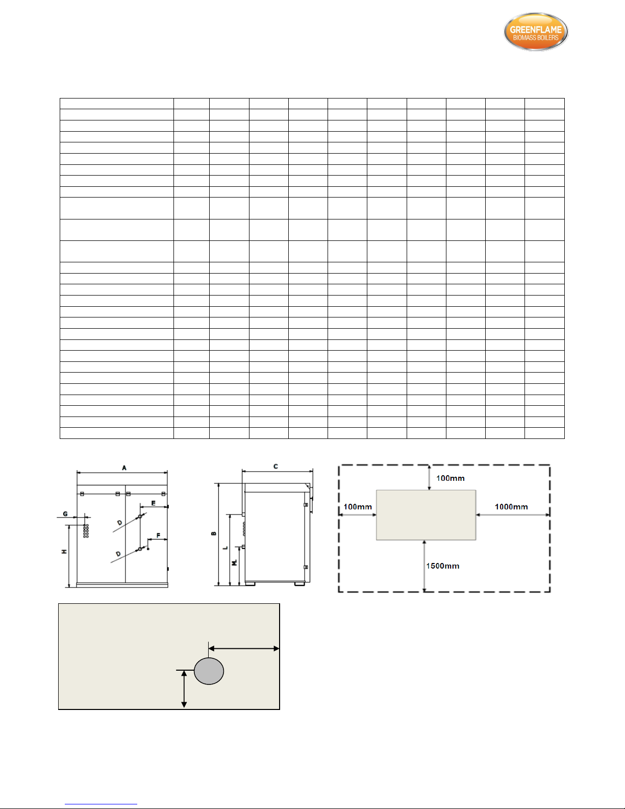
2.3 Basic Boiler Parameters:
*= large hopper store capacity
Model
10kW
10kW*
15kW
15kW*
25kW
25kW*
40kW
40kW*
60kW
60kW*
Power (kW)
1-10
1-10
1.5-15
1.5-15
2.5-25
2.5-25
3-40
3-40
4-60
4-60
Weight (kg)
320
335
320
335
320
340
375
400
420
460
Water volume (m3)
72
72
64
64
64
64
74
74
91
91
Flue gas outlet (kz-mm)
153
153
153
153
153
153
153
153
180
180
Width (A-mm)
1155
1460
1155
1460
1155
1460
1155
1460
1155
1460
Width (B-mm)
1275
1360
1275
1360
1275
1360
1375
1485
1375
1485
Depth (C-mm)
865
865
865
865
865
865
865
865
865
865
Internal Flue (kW-mm)
146
146
146
146
146
146
146
146
146
146
Minimum height of the
boiler room (mm)
1831
1916
1831
1916
1831
1916
1931
2041
1931
2041
Flue gas temp. at minimum
operation (°C)
90
90
90
90
90
90
90
90
90
90
Flue gas temp. at nominal
operation(°C)
120
120
120
120
120
120
120
120
120
120
Hopper (kg)
100
214
100
214
100
214
127
221
145
292
Working pressure (bar)
2 2 2 2 2 2 2 2 2
2
Chimney draught (mbar)
0.2
0.2
0.2
0.2
0.2
0.2
0.2
0.2
0.2
0.2
Fuel Consumption (kg/hr)
2.2
2.2
3.2
3.2
5.4
5.4
8.6
8.6
13
13
Efficiency (%)
91-95
91
95
91
95
91
95
91
95
91
Dimension (D-mm)
M 1 ¼
M 1 ¼
M 1 ¼
M 1 ¼
M 1 ¼
M 1 ¼
M 1 ¼
M 1 ¼
M 1 ¼
M 1 ¼
Dimension (E-mm)
340
340
340
340
340
340
340
340
340
340
Dimension (F-mm)
235
235
235
235
235
235
235
235
235
235
Dimension (G-mm)
95
155
95
155
95
155
95
155
95
155
Dimension (H-mm)
565
570
565
570
565
570
570
570
570
570
Dimension (I-mm)
330
330
330
330
330
330
330
330
330
330
Dimension (J-mm)
200
200
200
200
200
200
200
200
200
200
Dimension (L-mm)
885
885
885
885
885
885
985
985
1095
1095
Dimension (M-mm)
485
485
485
485
485
485
485
485
485
485
Dimension (N-mm)
340
340
340
340
340
340
340
340
340
340
Dimension (O-mm)
210
210
210
210
210
210
210
210
210
210
The lids and front doors may need to be removed for access through a
standard doorway.
The above parameter comparison for Greenflame Eco pellet boilers is
tentative. The manufacturer reserves the right to small variations to
some values in the above table.
O
N
Page 6
Greenflame Eco Installation Manual
6
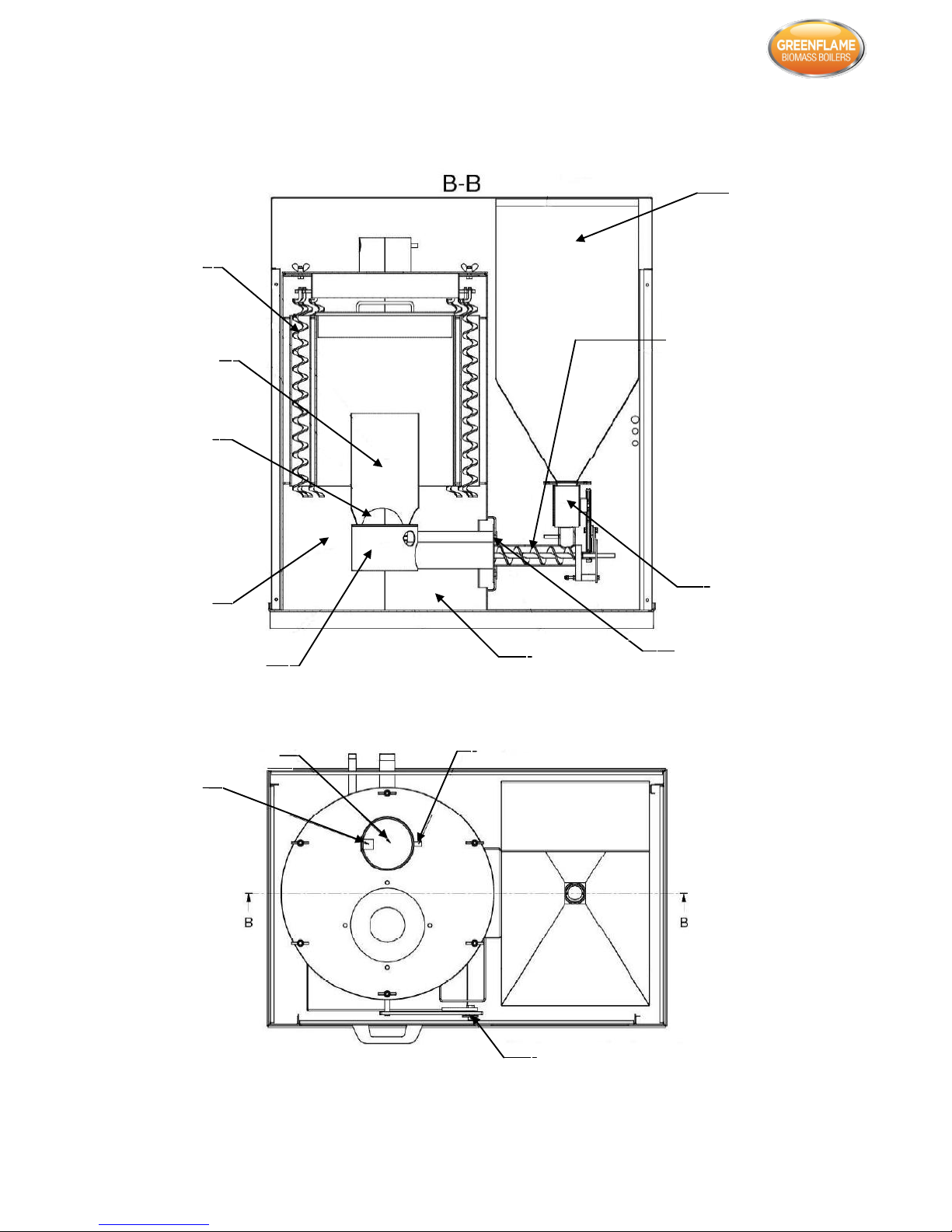
2.4 Construction of the Boiler:
Biomass hopper
Auger feed
Revolving hatch
Igniter
Ash pan
Burner
Separation
chamber
Automatic ash
removal from
fire place
Combustion
chamber
Turbulators
Exhaust outlet
Lambda probe
Exhaust probe
Automatic heat exchanger
cleaning system
Page 7
Greenflame Eco Installation Manual
7
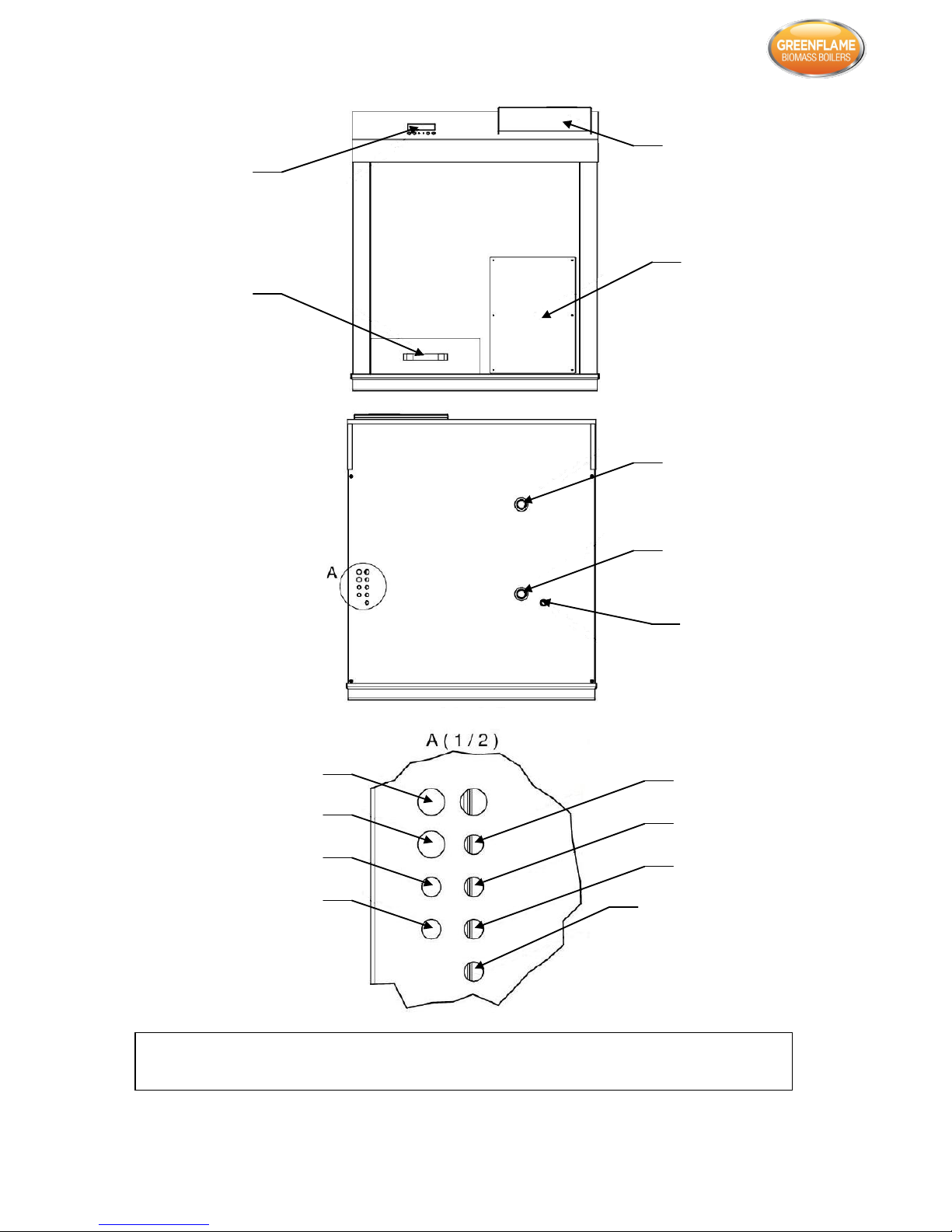
Container
cover
Electronics
cover
Display
Ash pan
Water flow
Water return
Drain
Central heating sensor
Buffer sensor
External sensor
Room thermostat/Programmer
Mixer
DHW pump
Central heating pump
Power supply
If not using either of the pump supplies, terminate to make safe. Cables can be traced back
and replaced if necessary, or alternatively extended using a suitable connector and cable.
Page 8

Greenflame Eco Installation Manual
8
The above drawings show the main boiler elements. They
have the following specifications:
Burner – made out of fireproof steel. Its geometry is
result of numerous tests and measures. Equipped with
air intakes on various levels which contribute to
increased combustion efficiency. Biomass is transported
from the hopper to the burner by means of the auger
feed. On contact with embers and in connection with air
supplied by many ducts the process of pyrolisis of
biomass occurs. Exhaust fumes created in the process
are directed through the heat exchanger to the chimney
outlet through the chimney duct which is enhanced by a
fan, which also serves a role of providing a sufficient
amount of fresh air for proper combustion. The amount
of fuel and fresh air supplied for combustion is
automatically matched by the controller based on
exhaust fume measurements (oxygen content in exhaust
fumes) provided by the Lambda probe.
Combustion chamber – made out of fireproof steel.
From the moment of starting the ignition process it
quickly gains high temperature, which in turn improves
the combustion process and reduces the amount of unburnt gas. It is also isolated between the flame and
boiler wall.
Revolving hatch – it is a factory assembled element.
Ensures perfect tightness between the hopper and auger
feed. Guarantees very precise dosage of pellets.
Ignitor – allows for completely automatic ignition of
pellets is controlled by the PCB.
Turbulator (turbulators) – designed to increase the
effectiveness of heat exchange by momentarily slowing
down the speed of the exhaust flow. Additionally, they
are periodically, automatically put in motion by this and
the heat exchanger is cleared of ash. Releasing the user
from performing the task.
Automatic heat exchanger cleaning system (turbulators
drive) – a reduction unit controlled by automatics of the
boiler, that propels the turbulators.
Exhaust Outlet – contains a box that can be removed to
gain access to the boiler. On top of the box there is an
exhaust outlet and a turbine, responsible for the
extraction of exhaust towards the chimney. The electric
motor that is driving the turbine is controlled by a
microchip via a voltage regulator, which provides
voltage based on the measurements provided by the
Lambda probe. This solution has been used for many
years. Bottom combustion has a lot of benefits, and also
prevents the fire getting to the pellet hopper.
Auger feed – worm-gear that works in a sequential
pattern depending on the demand of the burner. The
auger provides a small amount of fuel that is released by
the hatch. This allows operation under minimal load.
The decantation chamber – expanding area located
underneath the heat exchanger allows the deposition of
unburned particles and dust hovering due to lower
exhaust fume speed.
Ash pan – located under the burner. Collects ash that is
removed from the burner, ash that drops by force of
gravity, and also ashes that origin from automatic heat
exchanger cleaning.
Automatic removal of ash from fireplace – occurs by the
supplied pellet, and also by fresh air flowing through the
burner.
Lambda probe – located in the exhaust outlet. The
purpose of the Lambda probe is to control the content of
oxygen in the exhaust. Using the measurements it allows
the optimisation of the combustion process used for fuel.
In combination with the temperature probe it guarantees
correct boiler operation, and doubles as a safety device.
Exhaust probe – pilots the ignition and also manages the
power of the boiler. Another role is to protect the boiler
from unforeseen temperature raise.
Display – located on the front of the boiler. Allows
browsing through and editing of the available control
parameters.
Electronics cover – covers the electric box that houses the
heart of the control circuit.
Pellet hopper – its capacity depends on the power of the
boiler. Theres also the possibility to connect it to an
external feeder, which supplies fuel from a repository or
large silo.
2.5 Boiler Equipment
A standard Greenflame Eco pellet boiler consists of:
Burner,
Ignitor,
Lambda probe,
Control M RS 420 controller,
Central heating sensor,
Flue temperature sensor,
Weather sensor,
Additional paid options:
Pellet silo,
Vacuum system & pneumatic pellet supply.
The ‘vacuum system’ is an optional fuel transportation drive,
available on all ‘eco’ models. The system ensures smooth
transportation of pellet from fuel store to boiler. With sensor
indication controlling and monitoring the fuel supply. Should
the hopper empty the vacuum will automatically refill in
defined periods of time. Auger system available upon request.
Revolving hatch,
Pellet hopper,
Turbine,
Turbine motor,
Cleaner motor reduction unit,
Feeder motor reduction unit.
Page 9

Greenflame Eco Installation Manual
9
3. Setting Up and Installation of the Boiler:
3.1 Engineers Responsibility:
The installation of the boiler can only be performed by
qualified biomass engineers, complying with, and in line with
all rules, regulations and norms. The installer must also
comply with all recommendations, and directions provided
by the boiler manufacturer. Specifically this applies to the
instruction manual, boiler fitting method and its components
and also all hydraulic systems.
For any discrepancies, inconvenience, damage and injuries
that result from non-complying with regulations and
recommendations found in this manual the installer takes
the full responsibility.
3.2 Boiler Room:
Pellet boilers should be fitted in a specifically allocated room
(boiler room). The fuel deposit should also be located in an
allocated room near the boiler, however, not closer than
400mm from the boiler. To ease access to the boiler and to
enable maintenance, there should be at least 400mm of free
space around the boiler. The boiler should be positioned on
a non-combustible, thermally isolated base, which the
dimensions should exceed the dimensions of the boiler by at
least 200mm on all sides. If the device should be mounted in
a basement it is advisable to put it on at least a 50mm height
foundation.
It is mandatory to check if the boiler is perfectly horizontal,
and level to prevent air pockets from creating.
During the installation of the boiler it is advisable to provide
sufficient distance from inflammable materials, according to
the level of flammability.
If the level of flammability of material near the boiler is
unknown, the safe distance should be doubled (safe distance
is 200mm).
A permanent air entry air entry opening or openings with a
total free area of at least 550mm2 per kW of appliance rated
output above 5kW.
It is mandatory to fully follow all instructions and
recommendations regarding boiler room contained in this
instruction manual as well as in norms and regulations.
In case the boiler and its equipment is to be fitted in an
open space, where the temperature might drop below
15°C, or if the furnace might be subjected to conditions that
might be destructive to the device or any of the additional
equipment, such as presence of chlorine, acids or overly
humid air, the manufacturer is released from obligation to
provide warranty support for any part of the boiler, as well
as additional equipment. All doubts regarding the boiler
room should be directed to the manufacturer.
3.3 Ventilation and Exhaust – Chimney
System
Proper combustion also requires a proper exhaust chimney
system. The role of the chimney is to pipe away exhaust
fumes. The chimney required to complete this depends on:
Temperature difference between exhaust and surrounding
air;
Usable chimney height;
Diameter of chimney (no less than flue spigot diameter);
Chimney workmanship – as smooth as possible inner
surfaces an air tightness;
Usable chimney height is the difference between the highest
point of the fireplace and chimney outlet. This value should be
at least 4m for individual chimneys. In case of sloping roofs,
chimneys should end around the crest, in the area of smooth
wind flow – this way there’s no interruption of air draught. It is
always necessary to take into account the location and
orientation of the building in relation to surrounding buildings.
In most cases, to determine chimney parameters it is enough
to use the approximation method, or diagrams would not be
sufficient to determine an exhaust system. Chimney
parameters should be calculated according to regulations.
The cross-sectional area of the chimney should be 160 x
160mm. Improper cross-sectional area selection may cause
slowdown of exhaust fumes and in turn, deposition of ash
inside the chimney. If exhaust temperatures would drop below
the dew point, the water vapours and sulphuric acid might
cause damage to the wall.
The connection of the boiler and chimney should be made by
flue. They can be made as exhaust pipes, or exhaust channels.
Exhaust pipes are pipes or forms, which assembled inside
room. Exhaust channels usually comply with the fire
regulations for chimneys and are made of the same material
that the main chimney is made of. The connection between
the boiler and chimney should be as short as possible, and
assembled in a raising manner to reduce heat loss and
additional resistance. They cannot be guided to different
floors. Exhaust pipes shouldn’t be mounted in rooms where
fireplaces cannot be located and shouldn’t be placed in walls
and ceilings.
3.4 Hydraulic and Electrical Schematics:
Pellet boilers must be installed according to valid rules and
regulations by the authorised installation company. First startup must be performed by a service trained engineer and
authorised by T R Engineering Ltd that can show legitimate
validation document. The responsibility for proper boiler
installation and repairs is held by the installation/servicing
company, trained by the manufacturer, and that has
validation/authorisation. Any manipulation or changes made in
electrical parts of the boiler, or connecting additional
controller devices, might result in warranty loss.
Finalisation and test heating must be denoted on the boiler
warranty card. Lack of such information about start-up in
warranty card might result in warranty loss.
Hydraulic system should comply with BS 7593 and BS 5449 and
be executed according to building regulations.
Page 10

Greenflame Eco Installation Manual
10
Buffer tank (sized 10l per kW of
boiler output)
If not using either of the pump supplies, terminate to make safe. Cables can be traced back
and replaced if required, or alternatively extended using a suitable connector and cable.
Page 11

Greenflame Eco Installation Manual
11
Exhaust
probe
Buffer
sensor
L
-X1
High
limit
External
sensor
Central
heating
sensor
CS
N
N
L
LAMBDA
MODULE
O
2
0 – 5V
A2
LAMBDA
PROBE
16 17 18 19
IN IN H H
bk gy wh wh
OUT +5V GND bu bu bu bu bu bu bn bn bk bn bn 15 13 14
47nF
1 2 4 3 6 5 7 8 10 9 1 1 12
Room stat.
IN1 AGND IN2 IN3 AGND IN4 IN5 AGND IN6 IN7 AGND +12v IN8 GND
I1 I2 I3 I4 I5 I6 I7 I8
INPUT
Control Panel
1 2 3 4 5 6 7
8
LCD
S+
S-
CM
BUS+ BUS- GND
-G.B
iE5 A B
GND
A B GND
COMMUNICATION PORT
BOILER CONTROLLER
A1
O1 O2 O3 O4 O5 O6 O7 O8 O9 O10 O11 N L
OUTPUT
230V
MO M1 CW CO ZAP ZAS CS NC NC NC POD
N N N N N N N N L
L
N
N
N1
M
FEEDER
FEE
CLEANING
M
10 9 11
14
-KCS
LAMBDA
MODULE
-M5
A2
A1
A1
A2
A2
A1
VAC
IGN
-M3
-M2
M
M
M
VACUUM
IGNITER
CENTRAL
HEATING
PUMP
PUMP
DHW
MIXER
OPEN
CLOSE
-M1
1 0 6 5 4 3
-X2
N
L
Page 12

Greenflame Eco Installation Manual
12
CM
S+S-
X2
X1
1 2 3 4 5 6 7 8 9 10 11 12 13 14 15 16 17 18 19 PE
1 2 3 4 N PE 5 N PE 6 N PE 7 N PE 8 N PE 9 N PE 10 N PE 11 12 13 N PE 14 15 16 17 N PE
Exhaust
probe
blue
brown
black
grey
white
white
Buffer
sensor
High
limit
External
sensor
Central
heating
sensor
Room
stat.
Lambda
probe
STB
Mixer
DHW
Pump
Central
heating
pump
Igniter
Vacuum
Cleaning
Feeder
Fan
L L L
L
Supply
close
open
Page 13

Greenflame Eco Installation Manual
13
L
N1
N1
N
-X2
1
c
L1 L2
-G.A
U V W G
iE5
11
12
13
U
V
W
M
3 ~
FAN
-M6
N 8 N L N
N
M
-M4
VACUUM
IGNITER
-R
L
-X2
7
IGN
VAC
11
14
14
11
2
1
L
-X2
-F
D20
-X1
YE / GN
PE
N
-X2
L1
3 X2.5
L1
N
N
Page 14

Greenflame Eco Installation Manual
14
Room stat.
Central
heating
sensor
External
sensor
High
limit
Buffer
sensor
Exhaust
probe
N L
IN 1 AGND IN2 IN3 AGND IN 4 IN5 AGND IN 6 IN 7 AGND +12 IN 8 GND 01 02 03 04 05 06 07 08 09 010 011 N N N N N N N
230v ~
IN IN H H OUT +5 GND
CONTROLLER LAMBDA SENSOR N L 230v ~
WHITE
WHITE
GREY
BLACK
M M
M
M
IGN
FAN
M0
M1
DHW
heat
IGN
VAC
FAN
FEED
RM2
A2 A1
14 12 11
cϵ cϵ
e
Estyma
www.estyma.pl
electronics
REGULATOR PRACY KOTLA
ESTYMA control M RS
NUMER SERYJNY:
ZASILANIE 230V~50Hz
POBOR MOCY 5VA; T60
e
Estyma
electronics
www.estyma.pl
Page 15

Greenflame Eco Installation Manual
15
Plug Connection of Water Mixer:
A blending valve can be used for back end protection. This
is controlled by the connections above.
Requirements regarding water that is in central heating
circuits are the following:
Water must be clean and treated to BS 7593;
Hardness of water below 20°F;
PH below 8.5
The boiler is dedicated to following electrical parameters
230V/50Hz. Electrical systems should be executed by a
qualified person that will create a 230V/10A double pole
isolator, in an easily accessible place. Electrical supply of the
boiler and lighting should be connected to separate circuits.
3.5 Boiler Start-up by the User
The programmer is a modern microprocessor system which
controls not only the boiler, but also the central heating
system and Domestic hot water.
The unit controls the amount of fuel fed through the auger,
and the air supplied to the combustion process. Thanks to
solid stat relays (SSRs), the fan has variable speed control
and the reliability of the unit controlling the auger motor is
greatly increased.
Automatic fuel ignition – The control unit provides
automatic fuel ignition.
Measurement of waste gas temperature – The control unit
measures waste gas temperature which is an essential
parameter in a boiler with automatic start-up. Waste gas
temperature readouts are also very useful when inspecting
the boiler and adjusting its operation.
Large alphanumeric display – facilitates communication
between the unit and the user.
Lambda sensor – ensures optimum supply of air to the
combustion process, thereby simplifying the work of the
operator; it also reduces fuel consumption and improves
combustion, reducing emissions of harmful substances to the
environment.
Pneumatic fuel feeding control system – allows the boiler to
operate for long periods of time without the need to add
fuel.
Heat exchanger cleaning control system – ensures that the
boiler retains high efficiency without the need to clean the
exchanger.
Thanks to advanced operation algorithm and the possibility of
controlling numerous parameters, the unit can be flexibly
adjusted to the needs of the heating system.
The controller has an output testing function. The function is
available in the MAINTENANCE MODE and checks the
correctness of electrical connections and the working order of
the controlled equipment (pumps, fan, auger, mixing valve
actuator) prior to starting the boiler.
3.5.1 Operating the Unit:
MENU NAVIGATION
Press “ENTER” to enter the main menu.
Browse the main menu using and buttons.
Press “ENTER” to enter the selected submenu. Press
“ESC” to enter a higher level. The main menu is shown in
figure 2.
Submenus are used to display and change operation parameters.
In order to change a parameter, press “ENTER” . The
parameter changed is displayed in cycles. In order to edit the
parameter value, press or arrow buttons. When
editing, you may cancel the changes by pressing “ESC” .
Press “ENTER” to approve changes. The boiler submenu
is shown in Figure 3 as an example. The whole menu is shown in
Figure 4.
NOTE!!! Data is saved whenever the main screen is displayed.
4 - ground
1 – neutral
2 -M1 - opening
3 -M0 - closing
MAIN MENU
>>BOILER
HEATING
HOT WATER
POWER TEST
INPUT
LANGUAGE
MANUAL MODE (OFF)
SERVICE MODE (OFF)
TEST (OFF)
BOILER
>>mode Summer
Boiler progr. 70°C
Hysteresis 04°C
Figure 2: Main Menu
Figure 3: Boiler
submenu
Page 16

Greenflame Eco Installation Manual
16
Feeder no
145(s)
09(s)
Vacuum syst. no
Set password
100
SERVICE MODE
>>
min. Pumps temp
50°C
igniter[min]
02
flame test[min]
03
bl. Ignites[min]
02
fan at light
90
Talarm boiler
90°C
Tmin boiler
50°C
stop HP/hwp
20
work HP/hwp
05
Pumps rundown
10
Anti-bloc [sec]
20
Tmax. Heating
70°C
Max Fee/10sec
4.0
Min power
20%
Vacuum system [s]
20
Clean. Interval
03
Vacuum syst.
no
POWER TEST
o2=170
>>
power test
no
progr. power
30%
fan at power 20%
15
fan at power 40%
25
fan at power 60%
35
fan at power 80%
45
fan at power 100%
50
oxygen at 20%
190
oxygen at 40%
180
oxygen at 60%
170
oxygen at 80%
160
oxygen at 100%
150
MAIN MENU
>>
BOILER
HEATING
HOT WATER
POWER TEST
INPUT
LANGUAGE
MANUAL MODE (OFF)
SERVICE MODE (OFF)
TEST (OFF)
BOILER TEMP.
70°C
HOT WATER
70°C
EXHAUST TEMP.
45°C
ON
fa 30
BOILER
>>
Mode
Summer
Boiler progr.
70°C
hysteresis
04°C
HEATING
>>
Temp. calculat
45°C
reduction
15°C
Curve
0.8
shift
00°C
Feeder no
145(s)
09(s)
Vacuum syst. no
HOT WATER
>>
progr. h.w.
70°C
priority
yes
hysteresis
4°C
boiler h.w.
70°C
INPUT
>>
boiler temp.
70°C
hot water temp
70°C
pellets
no
heating temp.
20°C
outside temp.
+24°C
exhaust temp.
20°C
oxygen
155
thermostat
no
LANGUAGE
>>
selected
English
TEST (OFF)
* * *
NOTE: These values will be different for each
model Please see below figures as guidance.
10kW
15kW
25kW
45kW
60kW
Bl. Ignites
04
04
04
Max Fee/10sec
2.5
3.0
4.5
Figure 4: MENU
Page 17

Greenflame Eco Installation Manual
17
3.5.2 Amount of air, Lambda sensor –
Power Test Mode:
The combustion process requires the supply of air, the
amount of which depends on the type of fuel and the power
of the heating unit. Therefore, the optional amount of air
should be set for each type of fuel and each burner power
level. This should be down by the person who starts up the
control unit. The parameters are saved in the non-volatile
memory of the control unit. In order to set the optimal
amount of air, you should:
Set the type of fuel corresponding to the fuel to be used,
Turn on the control unit,
Enter the POWER TEST submenu and run the “power
test mode”,
Set the amount of air for 20, 40, 60, 80 and 100% of the
burner power. The values will be calculated by
approximation method from the selected curves. See
figure 6.
If the control system includes the optional Lambda module,
oxygen values should be set in a similar fashion for the
various burner power levels. The parameters should be set in
line with the boiler manufacturer’s specifications, or on the
basis of the results of waste gas analysis at the different
burner power levels.
If the fan power is controlled using the Lambda sensor
module, the fan power may be adjusted within the range ±10
adjustment units. This relationship is shown in Figure 7.
NOTE!!! Turn off the chimney sweep mode once you have
completed the adjustments.
When adjustments are made in the power test mode,
automatic burner power control is deactivated so as to allow
measurements and analyses at constant burner power.
Figure 5: Power Test submenu
3.5.3 Air during Ignition:
The amount of required air for ignition is set separately because
it differs from the amount of air during normal operation of the
burner.
Air amount during ignition is set using the “bl.ignites” parameter
in the service “SERVICE MODE” submenu. See table on page 16.
3.5.4 Pumps:
In order to be efficient and last long, the boiler must operate
within a certain temperature range. This is why the circulation
pumps should only run when the temperature exceeds a certain
minimum level. The “min. pumps temp” parameter is available in
the “SERVICE MODE” submenu. This should be set to 50°C.
3.6 Menu Language:
The menu of the control unit is available in a number of
languages: Polish, English, German and French. The preferred
language may be selected in the “language” submenu. The
default setting is English.
POWER TEST
o2=170
>>
power test
no
progr. power
30%
fan at power 20%
15
fan at power 40%
25
fan at power 60%
35
fan at power 80%
45
fan at power 100%
50
oxygen at 20%
190
oxygen at 40%
180
oxygen at 60%
170
oxygen at 80%
160
oxygen at 100%
150
Figure 6: Blower power curve
Figure 7: Blower power curve with Lambdabased control
Page 18

Greenflame Eco Installation Manual
18
3.6.1 Start-up:
Press the “ON/OFF/ESC” button for 3 seconds in order to
turn the control unit on or off. The current status of the unit
is displayed on the main screen:
OFF – the control unit is turned off (only alarm functions are
active while the fan and auger are controlled manually).
ON – the control unit is on.
NOTE!!! When off is displayed on the screen, the control unit
is actually in a standby mode and is energised; in case of an
alarm, the control unit will initiate the appropriate remedial
actions (i.e. it will either turn on the pumps or the auger).
If you intend to not use the boiler for a considerable period
of time, or to do any maintenance on the boiler, you must
de-energise the control unit by isolating the power supply.
The display (main screen) shows the current status of the
different pieces of equipment.
Boilers with the M RS 240M control unit are ideal for
domestic hot water both in the heating season and in other
parts of the year.
Both sensors supplied with the unit, should be installed in
the buffer tank and the following settings should be set up.
Figure 8: Boiler submenu
Figure 9: Hot water submenu
If the abbreviation of a particular piece of equipment is
displayed, it means that the control unit has turned it on.
ABBREVIATION
DESCRIPTION
HP (not used)
Central heating pump is on
WP
DHW circulation pump is on
Lig
Heating element is on
Fee
Auger is on
Fa20
Fan is on; current fan power level
00
Mixer closing
01
Mixer opening
Table 1: Equipment abbreviations
3.6.2 First Boiler Ignition:
If you work with an auger, you should fill the bin full with
fuel then turn the auger on manually in order to feed the
BOILER
>>
Mode
Summer
Boiler progr.
70°C
hysteresis
04°C
HOT WATER
>>
progr. h.w.
70°C
priority
yes
hysteresis
4°C
boiler h.w.
70°C
fuel into the combustion chamber. To do this, you should select
the “manual mode” submenu.
Press to turn the auger on/off.
Press to turn the suction on/off.
After you press the button, the auger will run for 30 seconds,
filling the burner with pellets about half way. Once this happens,
turn the boiler control unit ON; the fuel will ignite automatically.
3.6.3 Alarms and Safeguards:
The flashing of the display screen of the control unit is an alarm
signal. Press “ENTER” to display information about the alarm.
The control unit activates the following types of alarms:
Boiler overheating; alarm is activated when the boiler
temperature exceeds the “Talarm boiler” which may be set
in the “service mode”. When this happens, the control unit
on the circulation pumps and keeps them running until the
boiler temperature drops, regardless of the operating modes
selected.
NOTE!!! The circulation pumps will be turned on and will run in
pre-alarm mode when the temperature rises to 2°C less than the
boiler alarm temperature. If the temperature does not rise above
the alarm level, information on the incident will not be saved in
the control unit’s memory.
No flame/no fuel; the alarm is activated if the suction
system has made three consecutive failed attempts to ignite
the fuel.
NOTE!!! Once an alarm has been activated you should determine
and eliminate its cause.
The independent thermal boiler protection (ITBP); is
dependent of the microprocessor system. An independent
thermal switch will cut off the power supply to the fan if the
boiler temperature exceeds 94°C.
3.6.4 Programmer Technical Data:
PARAMETER
VALUE
Power supply
~230V/50Hz ±10%
Power uptake by the controller
<5VA
Carrying capacity of outputs
Central heating pump
100w
DHW pump
100w
Lighter
400w
Blower
150w
Feeder motor
200w
Automatic exchanger cleaning / suction
motor
100w
Mixer actuator
50w
Boiler temp. setting range
60-85°C
Domestic hot water setting range
35-70°C
Temperature measurement accuracy
±2°C
Ambient temperature
0-60°C
Humidity
5-95%, no condensation
Boiler alarm temp
80-95%
Page 19

Greenflame Eco Installation Manual
19
3.7 Restarting of the Boiler after
Interruption caused by Lack of Fuel:
In case of boiler extinguish caused by lack of fuel please
follow the instructions below:
Fill the hopper with fuel;
Using the manual fuel feed, transfer fuel until it reaches
the burner;
Remove ash arisen from complete burnout of fuel from
the burner;
Start automatic mode;
3.8 Final Information regarding
Installation and Boiler Start-up
To ensure prolonged, failure free operation of the boiler
please follow the rules below:
Supply sufficient chimney draught to allow optimal
combustion;
Secure the boiler from dampness and lack of chimney
draught by means of an acid-resistant or ceramic
chimney insert along with drainage of condensate to
sewer;
Position the boiler on thermally isolated flooring to
prevent it from developing water droplets on its walls;
Make sure that the central heating system is equipped
with a valve positioned on the lowest and as close to the
boiler as possible;
Remember that the start-up of the boiler should be
performed only by personnel trained by T R Engineering
Ltd with a current authorised service certificate;
Remember that a heating test must be performed after
boiler installation and must be noted in the warranty
card;
Remember that the boiler can only be operated by
adults, after reading and understanding this instruction
manual. It is forbidden for children to get close to the
boiler without adult supervision;
Shut down the boiler if any maintenance /repair work is
performed in the room that would involve gluing,
painting, etc. That might increase the risk of fire or
explosion;
Shut down the boiler during any periodical service or
boiler maintenance;
Ignite the boiler using only the automatic ignition
function. It is forbidden to use any solid or fluid
inflammable substance (such as gasoline, kerosene, etc);
Avoid overheating of the boiler;
Remember not to store any flammable material or
substances in the vicinity of the boiler;
Remember not to store any flammable material or
substances in the vicinity of the boiler;
Remember to keep the boiler temperature at 60°C, and
to utilise at least 45°C thermal protection at the water
return duct;
Remember to thoroughly clean the boiler and exhaust
duct. The boiler room should be kept clean and dry;
Remember that any intervention with electrical parts or the
construction of the boiler is forbidden and might result in
complete loss of warranty.
4. Cleaning and Maintenance of the Boiler:
In order to prolong the lifespan of the boiler:
Regularly clean the extracting vent fan – the turbine and
electric motor need to be removed and the dust removed
using a vacuum cleaner;
Regularly clean the Lambda probe – remove dust using a
vacuum cleaner, and wipe using a soft, dry cloth.
In case of any improper behaviour in the process of combustion
please contact your authorised service engineer that will perform
complex diagnostics and maintenance of the boiler.
At least once a year please call your authorised service engineer
for a service.
5. Warranty and Guarantee Conditions:
WARNINGS AND GUARANTEE / WARRANTY
INFORMATION
SAFETY INSTRUCTIONS
Installation of the boiler, making the electrical connections,
checking its operation, and maintenance are all tasks which
should be carried out by qualified and authorised personnel.
Install the boiler in accordance with the regulations in force in
your local area, region and country.
For the correct use of the appliance and to prevent accidents, the
instructions given in this booklet must always be followed.
Use, adjustment and programming must be carried out by adults.
Errors or incorrect settings may cause hazardous conditions
and/or poor operation.
Before beginning any operation, the user, or whoever is
preparing to operate on the appliance, must have read and
understood the entire contents of this instruction booklet.
All responsibility for improper use is taken entirely by the user
and such use relieves T R Engineering Ltd of any civil or criminal
responsibility.
Any kind of tampering or unauthorised substitution of nonoriginal spare parts can be hazardous for the safety of the
operator and relieves T R Engineering Ltd of any civil or criminal
responsibility.
Most of the surfaces of the appliance are extremely hot (the
boiler door, the handle, smoke discharge pipes, etc.). Avoid
Page 20

Greenflame Eco Installation Manual
20
coming into contact with these parts, without adequate
protective clothing or suitable implements such as gloves
with thermal protection or implements which keep the
hands cool.
Carefully explain this hazard to elderly people, disabled
people and particularly to all children, keeping them away
from the appliance while it is running.
Under no circumstances should the appliance be run with
the door open.
Do not touch the appliance with wet hands, in view of the
fact that it is an electrical appliance.
Before carrying out any cleaning or maintenance operation,
make sure in advance that the appliance is isolated from the
mains electricity supply, by removing the mains isolator fuse.
The appliance must be connected to an electrical system
which is equipped with an earth conductor, as laid down in
directives 73/23 EEC and 93/98 EEC.
The fuse must be of adequate rated capacity for the stated
electrical power of the appliance.
Incorrect installation or faulty maintenance (not conforming
to the requirements set out in this booklet) can cause harm
to people, animals or property. In such cases T R Engineering
Ltd is absolved from any civil or criminal responsibility.
Adhesive sealants and paints used in the manufacture of the
product are cured and present no known hazards when used
in the manner for which they were intended. The appliance
contains no asbestos.
OPERATING WARNINGS
Shut the appliance down in the event of a breakdown or bad
running.
Pellets must not be fed manually into the burner.
Accumulated un-burnt pellets in the burner after repeated
failed ignitions must be removed before re-lighting.
Do not wash the inside of the heat exchanger with water.
Do not wash the appliance with water. The water could get
inside the unit and damage the electrical insulation and
cause electric shocks.
Do not put any fuel, other than wood pellets, in the hopper.
Install the appliance in a location which is suitable for firefighting, and equipped with all services such as air and electricity
supply and provision for discharging combustion gases.
If there is a fire in the flue pipe, extinguish the appliance,
disconnect it from the power supply and never open the door.
Then contact the competent authorities.
If the appliance is in storage, it should be in a place that is free of
damp, and it should not be exposed to extremes of temperature.
It is inadvisable to base the appliance directly on a floor (if
located indoors), and if the floor is made of flammable material,
it must be suitably insulated.
Do not light the appliance with flammable materials if the
ignition system breaks down.
INFORMATION
In case of any problems, get in touch with your dealer, or a
qualified engineer authorised by T R Engineering Ltd, and if a
repair is necessary, insist on the use of original spare parts.
Use only the fuel recommended by T R Engineering Ltd (EnplusA1) may be used with this appliance.
Periodically check and clean the smoke outlet ducts (connection
to the flue pipe).
Accumulated un-burnt pellets in the burner after repeated failed
ignitions must be removed before lighting.
Always keep the cover of the fuel hopper closed.
Keep this instruction manual safe, it should stay with the
appliance throughout its working life. If the appliance is sold or
transferred to another user, always make sure that the booklet
goes with the product.
If lost, please contact T R Engineering Ltd or your authorised
dealer for another copy.
GUARANTEE CONDITIONS
T R Engineering Ltd offers the following warranties on this
appliance:
Leaks in the heat exchanger – 5 years
Faulty electrical components (motors, fan, controller) – 1 year
Pump, ignition element – 1 year
From the date of first ignition of the appliance as proved by a
Page 21

Greenflame Eco Installation Manual
21
valid commissioning report and the date on which the
commissioning report and the date on which the
commissioning took place. The guarantee is conditional on
the commissioning report being filled in and returned to the
manufacturer within 10 days, and requires that the product
be installed and commissioned by an approved T R
Engineering Ltd installer according to the detailed
instructions given in the instruction booklet supplied with
the product.
The term “guarantee” is to be understood to denote the free
of charge replacement or repair of parts recognised to have
been defective at the start by reason of manufacturing
defects.
Limitations
The above guarantee does not cover parts subject to normal
wear such as gasket, fibre board on doors and any parts
which can be removed from the firebox such as burner pot,
baffles and ash box. The replacement parts will be
guaranteed for the remainder of the guarantee period
starting from the date of commissioning of the product.
Exclusions
The warranty excludes all ancillary products associated with
the system (e.g. flue pipes, external circulation pumps, bulk
hoppers and augers, plumbing and electrical system). The
warranty does not cover issues arising from pellets that do
not conform to Enplus-A1.
Recommendations advised to the customer to be carried out
during commissioning must be completed and advised to
your local dealer in order to validate the warranty.
The requirement for the flue installation, particularly in
relation to draught, is the responsibility of the system owner.
Compliance with local building regulations must be adhered
to. The warranty does not cover misuse of the product
sabotage.
Any consequential loss or damage caused by the failure of a
component on this product is not covered.
T R Engineering Ltd refuses to accept any responsibility for
any damage which may be caused, directly or indirectly, by
persons, animals or things in consequence of the failure to
observe all the prescriptions laid down in the instruction
booklet, especially those concerning warnings on the subject
of installation, use and maintenance of the appliance.
Damage caused by transport and/or handling is excluded
from the guarantee.
The guarantee will be invalidated in the event of damage
caused by tampering with the appliance, atmospheric
agents, natural disasters, electrical discharges, fire, defects in
the electrical system, and caused by lack of fuel, or incorrect
maintenance in terms of the manufacturer’s instructions.
CLAIM UNDER THE GUARANTEE
The request for action under the guarantee must be addressed
to the Dealer/Retailer, who will forward the claim to T R
Engineering Ltd’s technical assistance service. T R ENGINEERING
LTD DECLARES THAT THE APPLIANCE WHICH YOU HAVE
PURCHASED CMPLIES WITH EEC DIRECTIVE 2004/108 EC AND
2006/95 EC AND SUCCESSIVE AMENDMENTS.
T R Engineering Ltd refuses to accept any responsibility in the
event that the appliance or any other accessory has been
improperly used or modified without authorisation. For all
replacement of parts, only original T R Engineering Ltd spare
parts must be used.
Page 22

Greenflame Eco Installation Manual
22
Date of Repair
Description of Conducted Work
Stamp and Signature of Service
Person
Page 23

Greenflame Eco Installation Manual
23
Date of Repair
Description of Conducted Work
Stamp and Signature of Service
Person
Page 24

Greenflame Eco Installation Manual
24
T R Engineering Ltd
Unit 7, Newton Chambers Way
Thorncliffe Industrial Estate
Chapeltown
Sheffield
S35 2PH
Tel: (0114) 2572300
Fax: (0114) 2571419
www.trianco.co.uk
©T R Engineering Ltd
Copyright in this brochure and the drawings and illustrations contained in it is vested in T R Engineering Ltd and neither the
brochure nor any part thereof may be reproduced without prior written consent.
T R Engineering Limited’s policy is one of continuous research and development. This may necessitate alterations to the
specification.
March 2014
Item No. 40000 Issue 2
 Loading...