

Page 1
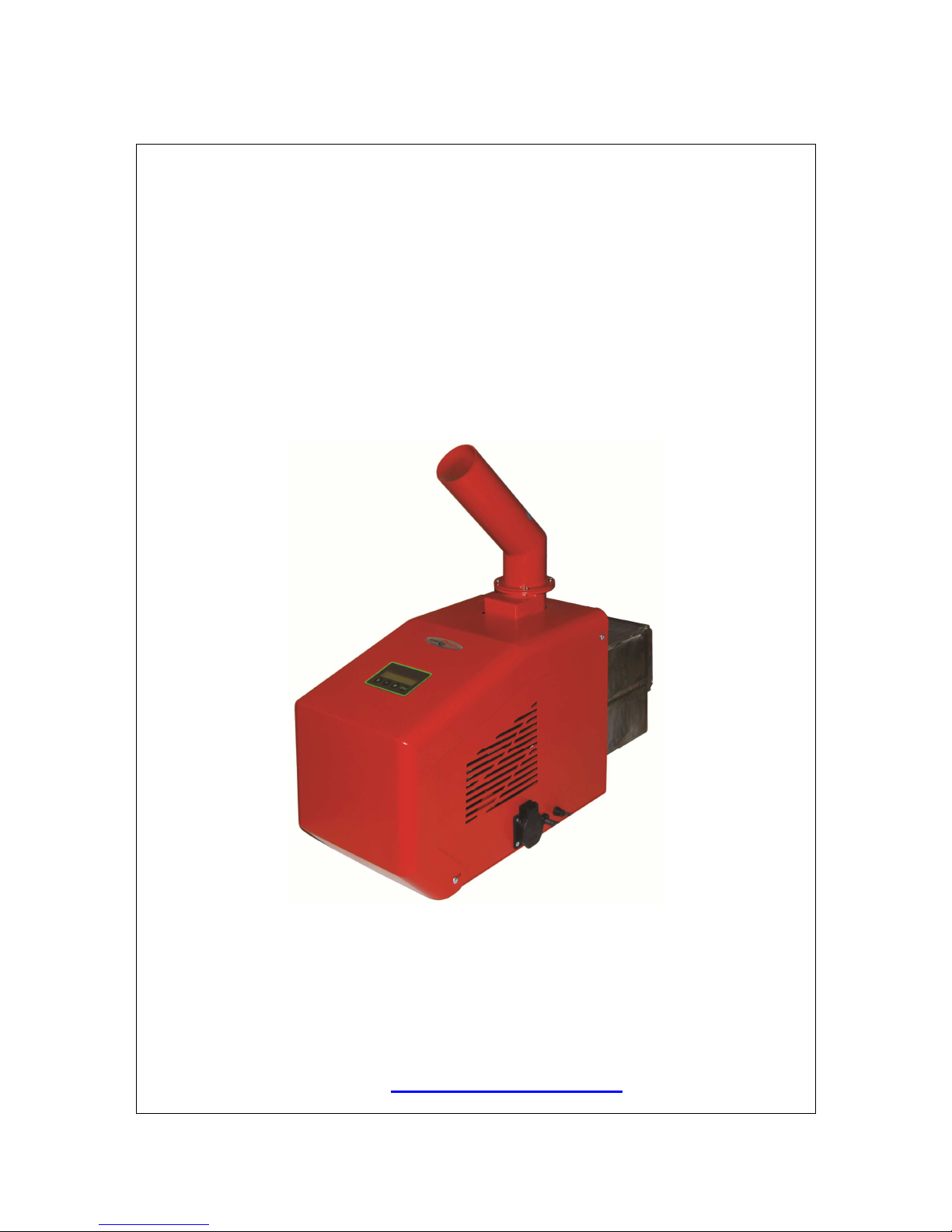
Pellet burner GP 45 IV 1
MANUAL
FOR INSTALLATION AND OPERATION OF AUTOMATED
MODULATING WOOD PELLET BURNER FROM SERIES
“GP 45 IV”
http:// www.greenecotherm.eu
Page 2

Pellet burner GP 45 IV 2
The manufacturing company thanks you for the contribution of your choice.
The manufacturing company provides this manual in help to the team that will install, adjust
and service this wood pellet burner, as well as to the customer that will operate it.
The manufacturing company requires that the technicians performing the above presented
procedures has passed training course for the activities performed with the product.
Manufacturer
ZMM Haskovo PLC.
Address
67 Saedinenie, 6300 Haskovo, Bulgaria
Telephone
+359 800 15 145
Fax
+359 38 603070
e-mail
home page
www.greenecotherm.eu
User manual for installation and operation of automated wood pellet burner from series “GP 45 IV”
(Edition: 1.2.2013 г. 13:52)
Page 3

Pellet burner GP 45 IV 3
CONTENT
page.
1. USER INFORMATION RELATED TO THE SAFETY.................................................... 5
2. DESCRIPTION AND ADVANTAGES OF AUTOMATED WOOD PELLET BURNER
FROM SERIES “GP 45 IV”................................................................................................ 6
3 TECHNICAL DATA OF AUTOMATED WOOD PELLET BURNER FROM SERIES “GP
45 IV ”................................................................................................................................ 8
4 CONSTRUCTION DESCRIPTION OF AUTOMATED WOOD PELLET BURNER FROM
SERIES “GP 45 IV”..........................................................................................................11
4.1. GENERAL CONDITIONS.....................................................................................11
4.2. CONSTRUCTIONAL MEASURES FOR INCREASING THE OPERATION
SAFETY OF THE BURNER FROM SERIES “GP 45 IV”.................................................15
5. MOUNTING AND INSTALLATION. .............................................................................17
5.1. MAIN REQUIREMENTS FOR INSTALLATION OF AUTOMATED WOOD PELLET
BURNER FROM SERIES “GP 45 IV”..............................................................................17
5.2. BURNER INSTALLATION ……………………………………………………………… 17
5.3. OVERALL AND CONNECTION DIMENSIONS OF THE BURNER’S MAIN
MODULE..........................................................................................................................18
5.4. POSITIONING AND MOUNTING OF THE BURNER’S MODULES......................20
5.5. INFORMATION ABOUT INSTALLATION POSSIBILITIES OF PELLET BURNER
FROM SERIES “GP” AND JOINT OPERATION WITH HOT WATER BOILERS............22
6. INITIALIZATION OF AUTOMATED WOOD PELLET BURNER FROM SERIES “GP 45
IV” IN OPERATION. .........................................................................................................23
6.1. MAIN REQUIREMENTS ABOUT THE USED FUEL.............................................23
6.2. INITIALIZATION OF AUTOMATED WOOD PELLET BURNER FROM SERIES
“GP 45 IV” IN OPERATION.............................................................................................23
6.2.1. INTERFACE CONTROL PANEL OF AUTOMATED WOOD PELLET
BURNER FROM SERIES “GP IV”....................................................................................24
6.2.2. CONNECTING AND POWERING THE BURNER.........................................24
6.2.3. SWITCHING ON THE BURNER FROM SERIES “GP”................................25
6.2.4. BURNER FROM SERIES “GP” OPERATION METHOD..............................26
6.2.5. PARAMETERS FOR OPERATION ADJUSTMENT OF A BURNER FROM
SERIES “GP”. ..................................................................................................................27
6.2.6. DESCRIPTION OF THE MENU, START AND ADJUSTMENT OF THE
BURNER’S OPERATION PARAMETERS........................................................................28
6.2.7. ADJUSTMENT OF THE BURNER OUTPUT ACCORDING TO THE HEAT
CONSUMPTION. ..............................................................................................................31
6.2.8. NOMINAL OPERATION MODE OF THE BURNER......................................31
6.2.9. OPERATION MODE OF THE AUTOMATED WOOD PELLET BURNER
FROM SERIES “GP IV”....................................................................................................31
6.2.10. USER MENUES FROM THE BURNER’S CONTROLLER............................33
6.2.11. USER MENUES FROM THE BURNER’S CONTROLLER............................33
6.2.12. MENU „EFFECT LEVEL”.............................................................................33
6.3. REGULATING THE BURNER’S HEATING OUTPUT. .........................................35
6.3.1. DECREASING THE BURNER’S HEATING OUTPUT. .................................35
6.3.2. INCREASING THE BURNER’S HEATING OUTPUT....................................35
6.4. STOPPING THE BURNER OPERATION.............................................................35
6.4.1 STOPPING THE BURNER OPERATION BY THE SWTICH “START”................35
6.4.2. STOPPING THE BURNER OPERATION BY THE CONTROL MODULE MENU.35
6.5. SWITCHING OFF THE PELLET BURNER FROM SERIES “GP IV” BY
EXTERNAL MODULE, CONTROLLING ITS OPERATION. ............................................37
6.5.1. BURNER EMERGENCY SHUT DOWN........................................................37
6.6. MENU FOR VIZUALIZATION OF ALARMS/ERRORS LIST, OCCURRED
DURING OPERATION OF PELLET BURNER FROM SERIES „GP IV”. ........................38
Page 4

Pellet burner GP 45 IV 4
6.7. RESTARTING THE PELLET BURNER OPERATION..........................................38
6.8. DESCRIPTION OF THE THERMO-STICKERS FUNCTION FOR MONITORING
THE SYSTEM CONDITION..............................................................................................39
6.9. REMOVING AND INSTALLING THE FIRE-GRATE DURING CLEANING AND
MAINTENANCE OF THE BURNER FROM SERIES “GP”..............................................40
6.10. INTRODUCING THE USER WITH THE MAINTENANCE AND ADJUSTMENT
PROCEDURES OF PELLET BURNER FROM SERIES “GP”.........................................42
6.11. SAFETY AND UNPREDICTED RISKS.................................................................43
6.12. COMPLETING THE BURNER’S WARRANTY CARD..........................................43
6.13. ACTIVITIES AFTER EXPIRY OF THE BURNER LIFE CYCLE PERIOD. ............44
7. FAILURES AND TROUBLESHOOTING..............................................................45
8. WIRING DIAGRAM OF AUTOMATED WOOD PELLET BURNER FROM SERIES “GP
IV”.....................................................................................................................................51
WARRANTY CONDITIONS
Page 5
Pellet burner GP 45 IV 5
1. USER INFORMATION RELATED TO THE SAFETY.
The installation and operation manual of the automated modulating wood pellets burner from
series „GP 45 IV” is designated for end users and authorized servicing specialists.
The user must know that:
All activities related to the wood pellet burner installation must be performed only by
authorized installers, which have acquired legal rights for such activities from the local
authorities;
All activities related to the electrical installation must be performed only by
electricians;
The initialization in operation, including visual check of the heating installation,
adjustment and burner start up, must be performed by certified technician, authorized
by the manufacturing company representatives;
Please observe the following rules during installation, initial start up, adjustment and
operation initialization of automated modulating wood pellet burner from series “GP 45 IV”:
All legal provisions related to the safety techniques;
Environment protection provisions;
Installation, initial start up and adjustment provisions;
The harmonized EU provisions, applicable in the relevant country;
Please strictly observe the presented safety instructions, in order to avoid risks and harms to
people, properties, as well as to environment polluting.
Please pay attention to the following symbols from the current manual book:
Danger
This symbol warns the users about possible human health risks.
Warning
This symbol warns the users about possible risks and harms to
properties and environment.
Information
This symbol provides additional information to the users.
Notation “GP IV” is used in the present manual book, which includes the wood
pellet burner model “GP 45 IV” with heating output of 45kW. The wood pellet
burners from series “GP IV” are modification of the already known pellet
burners from series “GP”.
For your safety it is important to become well familiar and read carefully
the present instruction, before performing any activities over the
installation and operation of this appliance. Non-observance of the
instructions below might lead to damages and fatal consequences, for
which the manufacturing company will not take responsibility.
Page 6

Pellet burner GP 45 IV 6
2. DESCRIPTION AND ADVANTAGES OF AUTOMATED WOOD PELLET BURNER
FROM SERIES “GP 45 IV”.
The automated modulating “GP 45 IV” series burner used for utilization of wood pellets is
designated for mounting to hot water boilers and other appliances. The burner utilizes wood
pellets and other types of biomass, described below, as the produced heating energy is
utilized by the hot water boiler’s body heat exchanging surfaces, in which the burner is
mounted.
The pellet burner from series “GP 4 IV” complete kit consists of:
Main module with removable fire-grate – 1 unit;
Fuel transport auger – 1 unit;
Flexible pipe – 1 pc, with tightening brackets – 2 pcs;
A pair of working gloves – 1 set;
Operation manual book – 1 pc;
Main module package – 1 pc;
Transport auger package – 1 pc;
User manual book for installation and operation of wood pellet burner from series
“GP 45 IV” – 1 pc.
The pellet burner from series “GP IV” can utilize the following types of fuel:
Wood pellets with diameter Ø 6-8 mm, category ENplus-A1 according to standard EN
14961-2:2010 or category: A, AB, B according to the methodic developed and used
by the burner manufacturing company;
Dry nuts (from cherries, from morello);
Mixture of pellets and dry nuts (for example 50% - 50% ratio);
Other biomass with pellet shape, but after test approval in the burner’s manufacturing
company laboratory.
The pellet burner from series “GP 45 IV” is fitted with:
Microprocessor controller for management of the burner’s modules operation;
Display with keyboard, showing the burner operation mode and for adjustment of the
burner operation parameters;
Firing air fan (fresh air) with Holl sensor that regulates the fan rotation frequency;
Electrical heating element, for fuel ignition (primary firing);
Transport auger, for automated fuel feeding from a hopper to the burner;
Combustion chamber, for establishment of optimized burning process;
Removable fire-grate, providing easy cleaning of the combustion chamber;
Photo-sensor for dynamic monitoring of the burning process;
Reversible thermo-sticker for indication of the system operation mode and the
necessity of cleaning, of either the appliance or the chimney to which it is mounted;
Irreversible thermo-sticker for indication of registered overheating of the burner, a
precondition for warranty claim disapproval.
The burner is equipped with:
Automatic fuel firing system;
Automatic system for fuel feeding to the combustion chamber;
Safety system, which block the burner fuel inlet, in case the pellets feeding pipe has
been overheated due to emergency situations;
Photo-sensor for dynamic monitoring of the burning process;
System for modulation of the firing air flow rate during the fuel ignition process;
System for modulation of the burner operation mode, which provides optimal
operation modes and low fuel consumption;
Availability for periodical performance of final combustion with blowing, used for
cleaning followed by new automatic restart.
Page 7

Pellet burner GP 45 IV 7
Advantages of the burner:
The burner is designated to utilize biomass, which makes it ecologically clean and
does not contribute to environment polluting;
Serves for changing hot water boilers fuel component, which previously have used
fossil fuels – oil, gas, coal;
Easy for mounting to boilers that are manually refueled with solid fuels – coal,
firewood, without necessity of significant reconstruction of the boiler installation;
The price of the produced heat energy from biomass utilization, as local energy
source, is less influenced than the global fuel prices, which makes the cost of the
acquired energy more competitive compared to the convectional heating sources;
The burner is automated and provides operation comfort near to that provided by
burners utilizing fossil fuels (for example liquid or gaseous fuel), which provides
availability for usage in systems equipped with programmable room thermostat;
The burner is equipped with automatic fuel ignition system;
Automatic operation of the burner, availability for smooth operation adjustment,
compatibility with room thermostat (weekly programmer), which guarantees maximum
heat comfort and fuel economy;
Modulation of the operating process, providing optimal operation parameters and
constant high efficiency;
Simplified installation and adjustment of the burner, which accelerates the installation
works;
Availability for utilization of biomass with pellet shape (wood pellets), dry cherry nuts
and others, according to the requirements presented in the fuel characteristics table;
High efficiency;
Low levels of harmful emissions;
Automatic fuel feeding from a hopper, which is built according to the local conditions
(the hopper is not part of the burner delivery kit);
Simplified maintenance and servicing;
Minimum operation costs.
Page 8
Pellet burner GP 45 IV 8
3 TECHNICAL DATA OF AUTOMATED WOOD PELLET BURNER FROM SERIES
“GP 45 IV ”
Heating-technical parameters of automated pellet burner from series “GP 45 IV” operating
with wood pellets are presented in Table 3.1.
Table 3.1. Heating-technical parameters of automated pellet burner from series “GP 45 IV”
operating with wood pellets.
Parameter Dimension Value
Burner model - GP 45 IV
Nominal heating output kW 45
Heating output adjustment range kW 14-45
Used fuel - Wood pellets, dry
cherry nuts
Wood pellets category, according to EN 14961-2 - ENplus-A1
Used pellets categories (according to the burner
manufacturing company classification)
- A, AB, B
Wood pellets consumption at nominal heating output kg/h 9.6
kg/h 75-90 Needed air quantity for efficient burning process
m3/h 70-84
Average wood pellet consumption in the heating
installation
kg/h 5.0-7.0
Wastes from fuel combustion Ash
The quantity
depends on the fuel
ash content and the
operation mode
The automated pellet burner from series “GP” is designated for utilization of wood
pellets that comply with the presented classifications, according to standard EN
14961-2, category ENplus-А1 and to the pellets categorization developed by the
burner manufacturing company. As an exception it is allowed to utilize noncomplying to the specification wood pellets, only for a short period of time (in a
few hours), mostly with higher ash content, which will require more frequent
cleaning of the ash gathered on the burner’s fire-grate and over the appliance
heat exchanging surfaces, to which the burner is mounted.
The presented values for average wood pellets consumption in the heating
installation refer to buildings and premises with good heat isolation and sealed
window frames.
Page 9

Pellet burner GP 45 IV 9
The dimensions and technical parameters of automated wood pellet burner from series “GP
45 IV” are presented in Table 3.2.
Table 3.2. Dimensions and technical parameters of automated wood pellet burner from
series “GP 45 IV”.
Parameter Dimension Value
Burner model - GP 45 IV
Main module kg 23.3
Weight
Fuel feeding auger kg 12.0
Main module mm 250х645х555 Overall dimensions
(WxLxH)
Fuel feeding auger mm 184x1870x107
Power supply - L1, N, PE, 50Hz; 230V;
Nominal mode A 0.2 Electricity
consumption
Ignition mode A 4.5
Electric power W
<100 + 800 (with
ignition)
Electric protection - IP20
Recommended fuel parameters are presented in Table 3.3.
Table 3.3 Recommended fuel parameters.
Parameter Dimension Value
Granules(pellets) diameter mm 6 - 8
MJ/kg >17.2 Recommended fuel caloricity (lower burning point)
kWh/kg >4.7
Wood pellets category according to standard EN
14961-2
ENplus-A1
Wood pellets category A, AB, B
Ash content % See table 3.4
Water content % Max. 8 – 10%
The wood pellets classification depending on their physical parameters and in accordance to
the methodic developed and implemented by the burner manufacturing company is
presented in Table 3.4.
Table 3.4. Wood pellets classification depending on their physical parameters and in
accordance to the methodic developed and implemented by the burner manufacturing
company.
Pellets category Ad DU
A
%6.0≤
d
A
%0.97
≥
DU
AB
%6.0≤
d
A
%0.97
<
DU
B
%0.16.0 ≤<dA
%0.97
≥
DU
BC
%0.16.0 ≤<dA
%0.97
<
DU
C
%0.2%0.1 ≤<dA
%0.97
≥
DU
CD
%0.2%0.1 ≤<dA
%0.97
<
DU
D
%0.3%0.2 ≤<dA
%0.97
≥
DU
DE
%0.3%0.2 ≤<dA
%0.97
<
DU
E
%0.3>
d
A
%0.97
≥
DU
EF
%0.3>
d
A
%0.97
<
DU
Page 10

Pellet burner GP 45 IV 10
Where,
A
d
– ash content of dry mass , [%];
DU – mechanical durability, [%];
With the acceptance of the new European Union wood pellets
standard (EN 14961-2) in 2010, new certificates, ENplus for pellets
used in boilers for domestic purposes and EN-B for industrial pellets
used in industrial boilers, are introduced. The standard ENplus defines
two quality categories: A1 and A2. In category A1 are implemented the
most strict limits for ash content in the pellets. In category A2 the ash
content is up to 1,5%. For industrial pellets the EN-B certificate is
applied, which is with significantly decreased quality requirements.
Table 3.5 European standard for wood pellets EN 14961-2.
Parameters Dimension ENplus-A1 ENplus-A2
Diameter mm 6 (± 1) 6 (± 1)
Length mm 3,15 ≤ L ≤ 40 1) 3,15 ≤ L ≤ 40 1)
Bulk Density kg/m³ ≥ 600 ≥ 600
Caloricity MJ/kg ≥ 16.5 ≥ 16.5
Water content % ≤ 10 ≤ 10
Dust % ≤ 13) ≤ 1
3)
Mechanical durability % ≥ 97.5
4)
≥ 97.5
4)
Ash content % 2) ≤ 0,7 ≤ 1.5
Ash melting point °C ≥ 1200 ≥ 1100
Chlorine content %
2)
≤ 0.02 ≤ 0.03
Sulfur content %
2)
≤ 0.05 ≤ 0.05
Nitrogen content %
2)
≤ 0.3 ≤ 0.5
Copper content mg/kg
2)
≤ 10 ≤ 10
Chromium content mg/kg
2)
≤ 10 ≤ 10
Arsenic content mg/kg
2)
≤ 1 ≤ 1
Cadmium content mg/kg
2)
≤ 0.5 ≤ 0.5
Mercury content mg/kg
2)
≤ 0.1 ≤ 0.1
Lead content mg/kg
2)
≤ 10 ≤ 10
Nickel content mg/kg
2)
≤ 10 ≤ 10
Zink content mg/kg
2)
≤ 100 ≤ 100
1) no more than 1% from the pellets can be longer than 40 mm, maximum length of 45 mm;
2) the data are determined with dry mass;
3) particles <3.15 mm, fine particles, before deliver of the goods;
4) for measurements, performed with Lignotester maximum allowed value ≥ 97.7 mass %;
Page 11

Pellet burner GP 45 IV 11
4 CONSTRUCTION DESCRIPTION OF AUTOMATED WOOD PELLET BURNER FROM
SERIES “GP 45 IV”
4.1. GENERAL CONDITIONS
The pellet burner from series “GP 45 IV” consists of the following components/modules:
The main part of the system is a main module that consists of:
Combustion chamber, which forms the conditions for optimal burning process
and is made of high quality stainless steel;
Combustion chamber fire-grate, which is easy removable and provides
availability for cleaning of the ash deposits;
Air distribution tract, which provides uniform supply of firing air and also air for
cooling of the burner’s parts;
Electrical heating element, which serves for primary ignition of the fuel,
positioned in the combustion chamber under the tilted part of the fire-grate;
Firing air supply fan, equipped with sensor for reading the rotation frequency
and availability for regulation;
Photo-sensor for monitoring of the burning process, mounted on the burner’s
side for its easy cleaning;
Emergency temperature sensor for protection from the so called “back fire” in
the main module’s fuel inlet pipe;
Control module for monitoring and managing the burner operation;
Display module with keyboard, used for visualization of the burner operation
mode and for performing all necessary adjustments;
Connector for the fuel transport auger, used for the auger power supply;
Reversible thermo-sticker, used for monitoring of the temperature in specific
zone of the burner and for evaluating the necessity for cleaning of the
appliance to which it is mounted, or for evaluating the necessity of inspection
of the chimney draught;
Irreversible thermo-sticker, for indication of registered overheating of the
burner, precondition for warranty claim denial.
Electrically driven outer transport auger, which transports the fuel from a hopper to
the burner, depending on the burner operation mode. The auger consists of motorgear with electric motor, equipped with integrated overheating protection, pipe for
transferring the fuel to the drop hole (where it drops down by gravity) and to the
flexible pipe;
Flexible pipe, made of special transparent thermo-resistant material (in case of fire it
does not separate harmful or toxic substances), which connects the auger and the
main module.
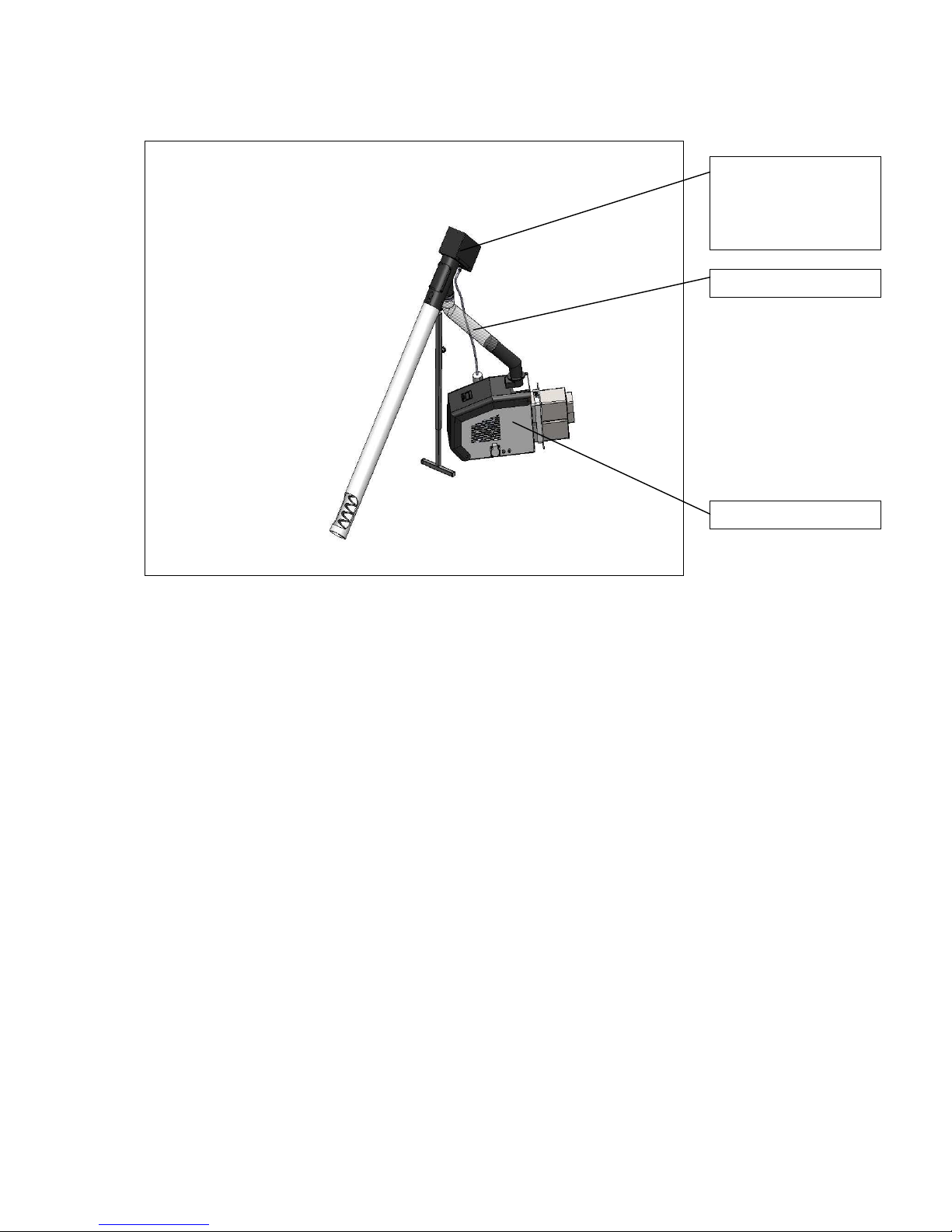
The main burner modules and their positioning are presented in Figure 4.1.
Page 12
Pellet burner GP 45 IV 12
Figure 4.1. Main modules positioning of burner from series “GP 45 IV”(side view).
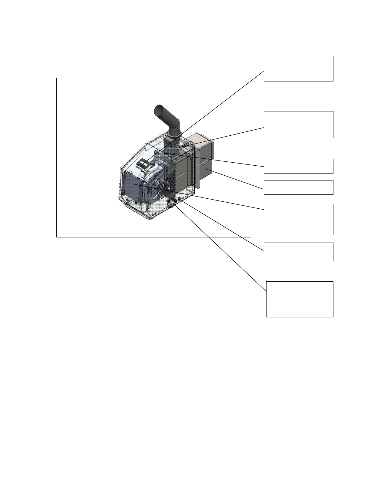
Main module’s components of a burner from series “GP IV” are presented on Figure 4.2 and
Figure 4.3.
Flexible pipe
Main module
Outer fuel transport
auger, from a
hopper to the main
burner module
Page 13
Pellet burner GP 45 IV 13
Figure 4.2. Main module section view and components of burner from series “GP 45 IV”.
`
Emergency sensor
protecting from “back
fire”
Interface panel
(display + keyboard)
Photo-sensor
Combustion chamber
Burner’s control pcboard
Burner’s power
supply cable
Plug for managing
and power supply of
the fuel transport
auger
Page 14
Pellet burner GP 45 IV 14
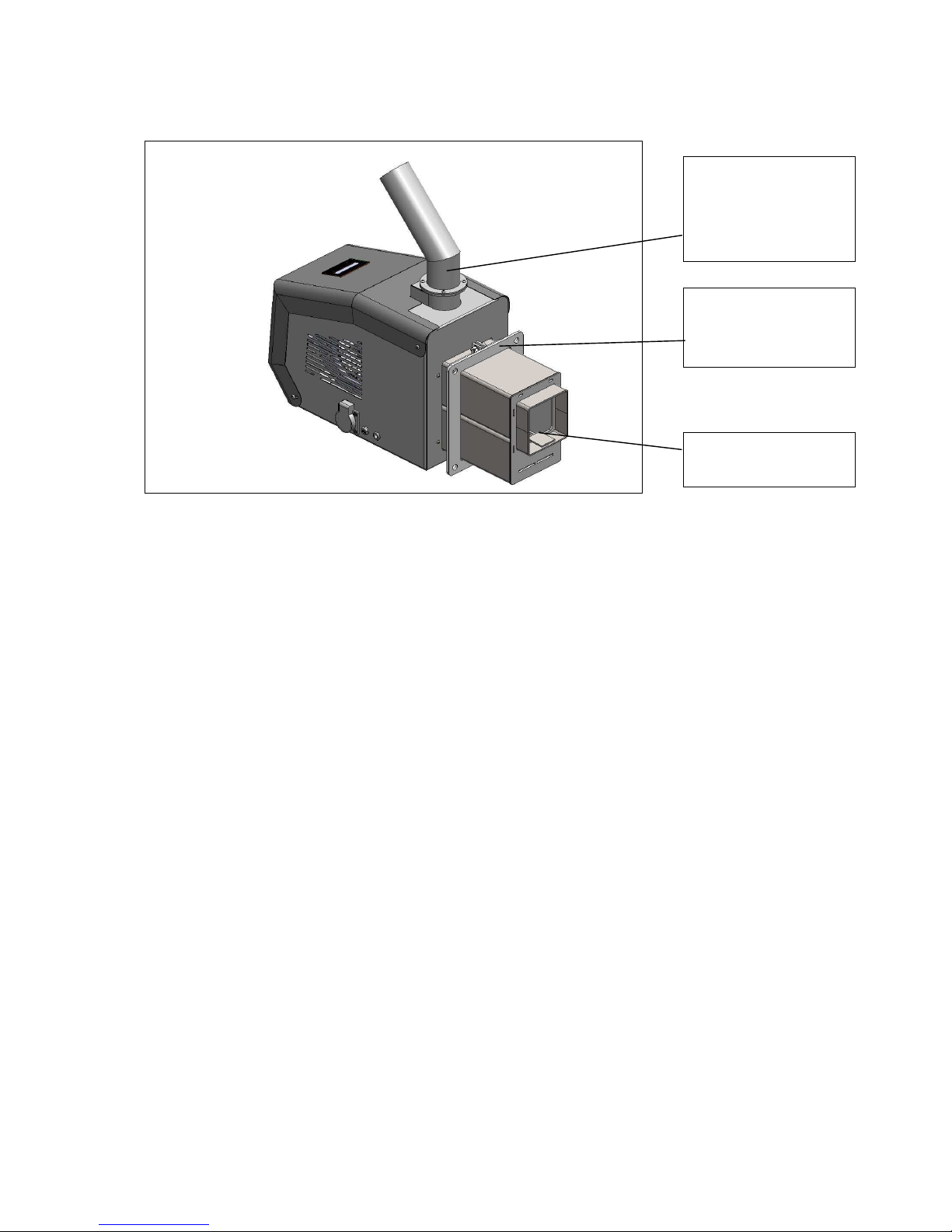
Figure 4.3. Main module view of burner from series “GP 45 IV”.
EXPLANATION:
The reversible (self-recovering) liquid crystal thermo-sticker serves for indication of
the temperature in the zone where it is attached. This temperature indicates also the
burner operation mode and the flue gas resistance within its route to the appliance’s
chimney, to which the burner is mounted. The initial condition of the thermo-sticker is
such that all of its temperature scale zones are dark colored. When the temperature
increases the surface of the scale zones become lighter, corresponding to the
operating temperature. Increase of the temperature in this zone indicates the
necessity for cleaning of the appliance from the ash deposits and/or the flue gas
extraction line. When it cools down the sticker reverse to its previous condition and
color;
The irreversible (not recovering) liquid crystal thermo-sticker is indicator for (at least
once) overheating of the burner’s pellet inlet pipe. This sticker has single action and
when it reaches critical temperature its color changes irreversibly. At initial condition
its indication element color is white and after its critical temperature has been
reached it becomes dark.
In case that the fuel transport auger of the burner has to be supported, then a telescopic
support can be ordered, as an optional equipment to the burner, which provides availability
for adjustment of the auger tilting angle and its stable positioning (Figure 4.4).
Pellets inlet pipe to
burner’s combustion
chamber
Main module
mounting flange to
appliance (to boiler)
Combustion
chamber fire-grate
Page 15

Pellet burner GP 45 IV 15
Figure 4.4. Fuel transport auger support bar view, for burner from series “GP 45 IV”.
4.2. CONSTRUCTIONAL MEASURES FOR INCREASING THE OPERATION SAFETY
OF THE BURNER FROM SERIES “GP 45 IV”
The ignition and burning processes are monitored by micro-processor logic module;
The ignition and burning processes are monitored by photo-sensor and if the fuel
does not fire after two attempts for ignition, then the burner transits to “Stop” mode
with relevant indication for transiting to such mode;
If during operation the fuel hopper has been depleted the burner transits to “Stop”
mode with respectively activated indication for transition in such mode;
The flexible pellets transport pipe is transparent and is made of special temperature-
resistant material;
There are stickers (labels) indicating the proper operation and handling of the burner;
The burner is equipped with safety components for protection against fuel firing
(occurrence of the so called “back fire”):
Dropping flap chamber, which cuts the pellets flow from the transport auger to
the main module. The chamber depth is around 250mm. Besides that the
transport auger is connected to the burner through flexible pipe, which is not full
with fuel. There is small doze of fuel in the burner, which burns completely while
the transport auger operation is paused and there is no risk of reverse firing of
the fuel;
Emergency temperature sensor, positioned on the burner’s fuel feeding pipe,
which activates when the surface temperature in this zone exceeds 90 – 95
o
C. If
during operation this sensor registers temperature increase (90 – 95oC), then
the transport auger stops and the system transits to emergency mode,
respectively the burner operation stops as well. This is indicated on the burner’s
display with the sign “STOCKER FAULT”. After removing the normal operation
disturbance reason the burner can be started again by switching off and then on
its power supply (restarting);
Page 16

Pellet burner GP 45 IV 16
The reversible thermo-sticker from liquid crystals, which indicates the current
temperature value in its attachment zone, serves for easy evaluation of the
system operation mode, where the burner is installed and the necessity for
cleaning of the appliance and/or the chimney tract/line.
Page 17

Pellet burner GP 45 IV 17
5. MOUNTING AND INSTALLATION.
5.1. MAIN REQUIREMENTS FOR INSTALLATION OF AUTOMATED WOOD PELLET
BURNER FROM SERIES “GP 45 IV”.
The burner has to be positioned in a way that provides enough free space for its
servicing and cleaning;
The burner has to be mounted to an appliance (hot water boiler, other heat energy
consumer) in a way that provides availability for easy servicing and cleaning from the
ash residues;
It is not allowed to mount the burner to appliance that is installed in living premises,
including corridors;
The burner mounting to an appliance must be performed by a qualified technician
only;
The installation and maintenance of the automated pellet burner must be performed
by specialized companies, which have acquired legal rights for such activities;
The automated pellet burner from series “GP” must be connected to the electrical
supply system by an authorized electrician only;
Before initialization of the burner in operation the heat energy consuming devices
working order must be ensured;
The burner servicing/handling must be performed by adult persons only, which are
well familiar with the appliance operation manual book.
The burner mounting to a hot water boiler (consuming appliance) has to be done
by bolts (or studs) and nuts. It is required to fasten the burner to the appliance
with the use of a tool (for example wrench). It is not allowed to fasten it by hand.
The mounting and removal of the burner must be performed by an eligible person
equipped with proper tools.
5.2. BURNER INSTALLATION.
The burner installation to an appliance requires preliminary prepared project, complying with
the acting norms and regulations.
In case the heat consuming appliance is a hot water boiler, then the requirements of
standard BNS EN 303-5/2000 – “Central heating hot water boilers - part 5: Central
heating solid fuel hot water boilers with nominal heating output of maximum 300 kW –
terminology, requirements, tests and notation” must be observed;
In case the heat consuming appliance is not a hot water boiler, then the prescribed
standard requirements for the relevant appliance type, must be observed;
Fire safety requirements;
To the electrical supply network - BNS EN 60335-1/1997 – “Safety of domestic
electrical devices”
Observe the chimney draught requirements, presented in the hot water boiler’s
technical data table, when installing the burner to the boiler.
Page 18

Pellet burner GP 45 IV 18
5.3. OVERALL AND CONNECTION DIMENSIONS OF THE BURNER’S MAIN
MODULE.
When mounting the burner to an appliance the installation requirements have to be
observed, as well as the main module dimensions presented on the next figures.
Figure 5.1. Main module of a pellet burner from series “GP 45 IV”, isometric view – both
sides view.
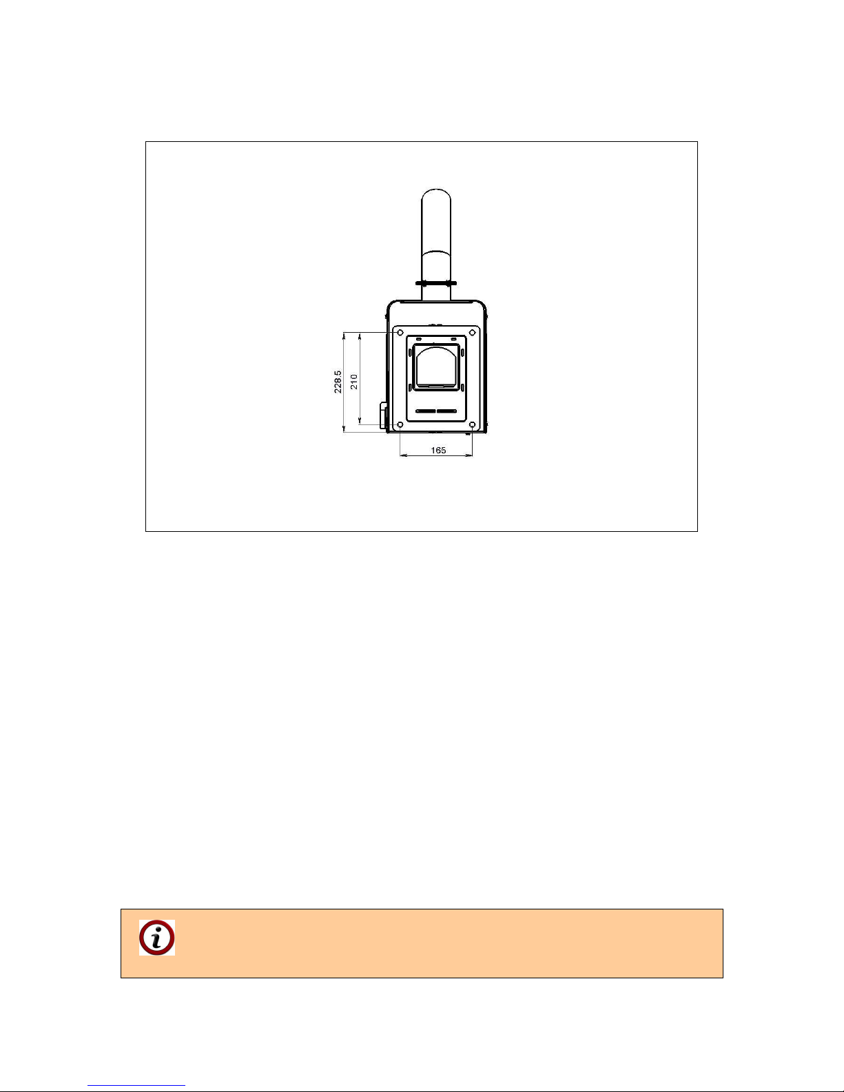
The coupling dimensions of the burner’s main module, which must be observed when
mounting and installing the appliance, are presented on figures 5.2, 5.3 and 5.4.
Page 19

Pellet burner GP 45 IV 19
Figure 5.2. Main module overall dimensions of a burner from series “GP 45 IV”
(side view).
Figure 5.3. Main module overall dimensions of a burner from series “GP 45 IV”
(top view).
Page 20
Pellet burner GP 45 IV 20
Figure 5.4. Main module overall dimensions of a burner from series “GP 45 IV”
(front view).
5.4. POSITIONING AND MOUNTING OF THE BURNER’S MODULES
The main module of the burner from series “GP” must be mounted horizontally to the
appliance that will consume the generated heat energy, produced by the fuel combustion.
Depending on the appliance type a technical evaluation for the main module position has to
be performed, so reliable operation, easy cleaning, servicing and maintenance are ensured,
as well as for reliable and high efficient co-operation of the burner and the heat energy
consuming appliance. The main burner module has to be installed to the heat energy
consuming appliance by using the attached sealing.
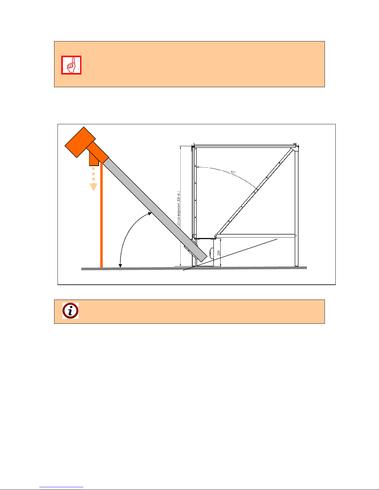
The fuel transport auger must be positioned near to the burner, so it can be connected to the
main module by the flexible pipe, through which the fuel from the auger drops. It is also
recommended to ensure 45o tilt angle between the transport auger axis and the horizontal
plane, which ensures optimal operation conditions for the auger motor and for the burning
process. The bottom (suction) part of the auger has to be positioned in the lowest point of the
fuel hopper, so its constant filling is ensured. The fuel transport auger and the fuel hopper
have to be positioned in a way providing easy manipulation with the burner’s main module,
for the purposes of cleaning and servicing, as well as for proper mounting of the feeding
flexible pipe.
To ensure optimal operation conditions of the fuel transport auger it is
recommended to use a fuel hopper model “BP” – manufactured by the burner
manufacturer. This hopper is not part of the “GP” series burner standard delivery
kit.
Page 21
Pellet burner GP 45 IV 21
The auger tilt angle change leads to change in the fuel consumption and
respectively to the burner’s heating output:
- decreasing the auger tilt angle leads to increased fuel consumption,
respectively to increased heating output;
- increasing the auger tilt angle leads to decreased fuel consumption,
respectively to decreased heating output.
Schematic view for installation of the fuel transport auger is presented on Figure 5.5.
Figure 5.5. Schematic view for installation and positioning of the fuel transport auger.
The auger on the above figure is equipped with support bar, which is additional
option (not standard equipped) to the burner delivery kit. The tilt angle between
the auger axis and the horizontal plane has to be 45o.
The fuel transport auger can be mounted to a fuel hopper that provides capacity up to 650 kg
of wood pellets (Figure 5.6).
45о
Fuel hopper
“BP”
Page 22

Pellet burner GP 45 IV 22
Figure 5.6. View of a fuel transport auger mounted to a fuel hopper with additionally installed
storey.
The flexible pipe must be linked to the transport auger and the main module, so it
is fully stretched (without bents and hangings, where the fuel or fuel dust could be
gathered) and after that it has to be fastened with the attached brackets.
5.5. INFORMATION ABOUT INSTALLATION POSSIBILITIES OF PELLET BURNER
FROM SERIES “GP” AND JOINT OPERATION WITH HOT WATER BOILERS.
The automated pellet burner from series „GP” is individual module (requiring electrical supply
and signal – assignment for operation), that can be mounted to heat energy consuming
appliance. The practice shows that in most cases the heat energy consumer is a hot water
boiler for local heating installations. The manufacture company had accomplished continues
tests for compatibility, reliability and efficiency of the burner and series of popular hot water
boilers. Depending on the hot water boiler construction it is possible to use additional
transitional components and modules, which improve the system operation: pellet burner –
hot water boiler and ensure, and increase its efficiency and reliability.
Page 23

Pellet burner GP 45 IV 23
6. INITIALIZATION OF AUTOMATED WOOD PELLET BURNER FROM SERIES “GP 45
IV” IN OPERATION.
The automated modulating pellet burner from series “GP 45 IV” must be initiated
in operation only by specialized company, authorized for such activities.
6.1. MAIN REQUIREMENTS ABOUT THE USED FUEL.
To ensure complete fuel burning/utilization it is necessary to use only dry fuel. It is
recommended to store the fuel in dry ventilated premises;
It is forbidden to store the fuel next to the appliance to which the burner is mounted or
at distance less than 400 mm;
The optimal recommended distance between the appliance (to which the burner is
mounted) and the fuel is minimum 1000 mm. It is better to store the fuel in a neighbor
premise;
All fire safety requirements during the burner installation to the designated appliance
must be observed. It is recommended to have a fire-extinguisher on an easy
accessible and safe place.
6.2. INITIALIZATION OF AUTOMATED WOOD PELLET BURNER FROM SERIES “GP
45 IV” IN OPERATION.
GENERAL CONDITIONS:
The burner handling must be performed in comply with the operation and
maintenance manual;
The operation mode of the system: pellet burner from series “GP” and heat energy
consumer must provide minimum under-pressure (pressure lower than the
atmospheric) in the appliance combustion chamber, within the range of 5-20 Pa;
Non compliance with this requirement might lead to emergency operation modes
or to inefficient burner operation. The under-pressure value in the combustion
chamber of the heat energy consuming appliance depends on the chimney
draught and other modules (for example flue gas extraction fan). Operation
modes not complying with this requirement could be indicated by the reversible
thermo-sticker temperature value.
Any intervention over the system operation, that might endanger the health of the
servicing personal or to any other indirectly related persons is forbidden;
During operation the burner must be periodically inspected by the servicing/handling
personal/customer;
The user must not perform repairs over the system’s modules. If a problem occurs
during its operation, the user must ask for competent assistance by a servicing
company;
It is forbidden to increase the burner heating output over its nominal output;
The ash residues from the burning process have to be gathered in fireproof
containers equipped with covers and after their cooling to ambient temperature
should be dumped at proper for the purpose places.
Page 24
Pellet burner GP 45 IV 24
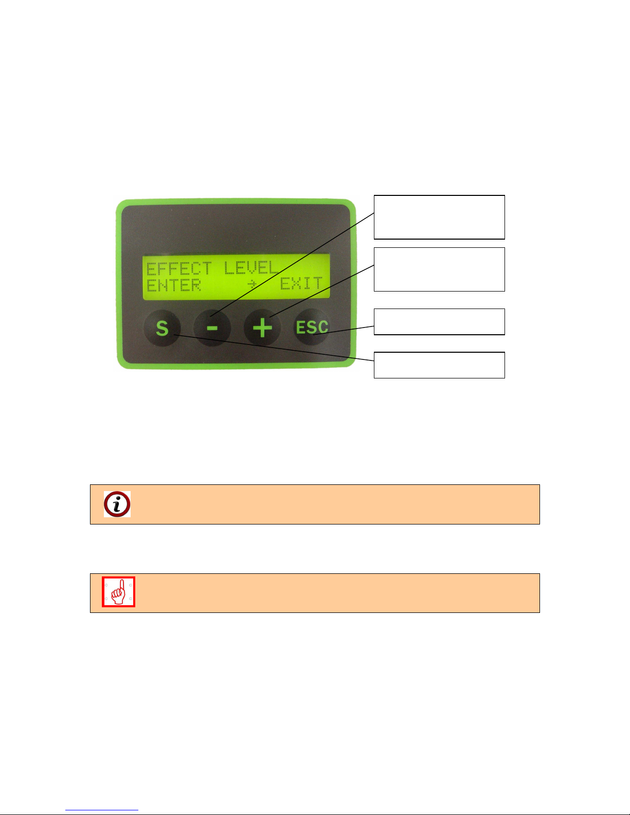
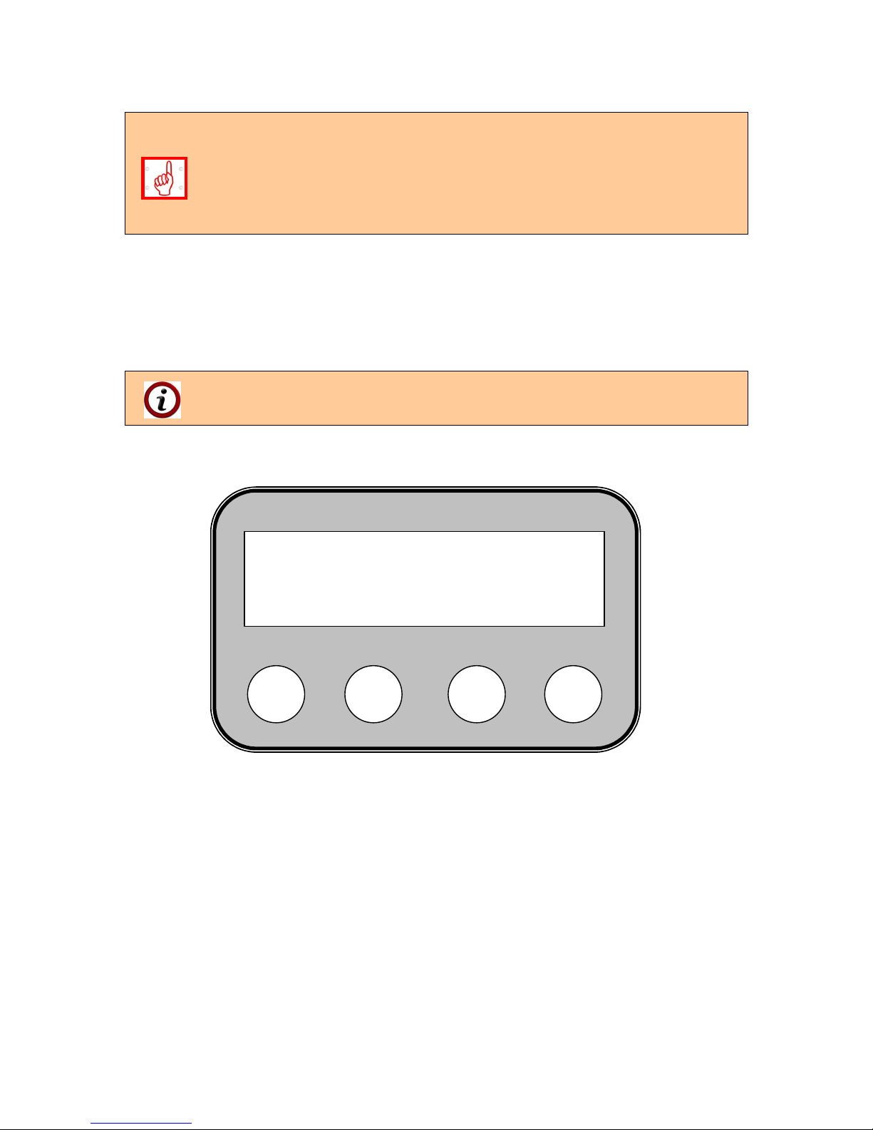
6.2.1. INTERFACE CONTROL PANEL OF AUTOMATED WOOD PELLET BURNER
FROM SERIES “GP IV”.
Figure 6.1 represents interface control panel with display of an automated pellet burner from
series “GP IV”.
Figure 6.1. Interface control panel with display and keyboard for pellet burner from series
“GP IV”.
Interface control panel components and their functions:
Button „ S ” – is used for submenu choice and for confirmation of settings;
Button „ - ” – is used for decreasing the selected value from the controller menu;
Button „ + ” – is used for increasing the selected value from the controller menu;
Button „ Esc” – is used for canceling a parameter change from the controller menu
and to exit a chosen menu.
The above described buttons on the burner’s interface control panel can also
perform different function, which will be shown on the display.
6.2.2. CONNECTING AND POWERING THE BURNER.
All activities over the burner’s electrical installation or adjustments that require
removal of its covers or other components protecting its electrical parts from
touching by hand must be performed by eligible person.
The burner must be connected to the electrical installation of the appliance to which it is
mounted by observing the safety technique rules. The power supply cable and the attached
wiring diagram for connection to the power supply and the main control module of the burner
must be used.
The fuel transport auger is mounted in the fuel hopper and is positioned in a way providing
the necessary fuel feeding rate and is also filled with fuel.
Button „-” (its function
depends on the chosen
menu
)
Button „+” (its function
depends on the chosen
menu
)
Button “Exit”
Button “Enter”
Page 25

Pellet burner GP 45 IV 25
The circulations water temperature sensor must be mounted in a muff for measurement of
the hot water boiler outlet water temperature or must be screwed in threaded orifice
(depending on the sensor type).
6.2.3. SWITCHING ON THE BURNER FROM SERIES “GP”.
The burner switching on is performed by the appliance power supply to which it is mounted.
If the burner has been in operation mode (or in “hot reserve”) but the power supply has been
interrupted, it automatically starts/continues operation when the power supply has been
restored.
During operation of the burner flue gasses are possible to flow through the
unsealed parts, eventually through the fuel inlet flexible pipe, if the appliance
to which it is mounted is not sealed properly. It is recommended to seal these
parts and to adjust the burner’s heating output in order to prevent flow of smoke
out of the appliance. The same effect can be monitored during the transition
seasons, autumn and spring, when the natural chimney draught is decreased
due to higher environment temperature.
The electrical heating elements, which are positioned over the combustion
chamber fire-grate, activate during the ignition mode. This zone heats to very
high temperatures and could be considered as a risk from burning, in case it is
touched by hand – it is not allowed to perform any manipulation in the
combustion chamber zone. If it is necessary to mix (spread) or remove fuel, then
proper personal protection equipment and tools must be used.
At initial burner operation start the fuel transport auger must be filled with pellets –
this is continues process requiring more time. The auger must be connected to
external power source through its standard plug and to wait until the pellets start
to drop down through the auger’s upper opening. After that plug the auger to the
burner’s main module power supply outlet.
The burner’s main module constantly checks if the fuel transport auger is
connected to it and if this condition is not fulfilled it activates an emergency
mode. In order to turn it back to normal operation mode the auger’s power supply
cable must be plugged in and the module restarted.
If the auger was plugged out of the burner’s main module (the controller reads
such situation as an emergency mode – i.e. no electric motor plugged) and the
burner was switched on, then an emergency mode activates and the burner does
not operate. In order to reset the alarm it is necessary to switch off and then back
on the burner’s main power supply, but after the auger has been plugged in the
burner’s main module.
The burner operates by preliminary installed algorithm based in its control
module. The optimal parameters for operation are adjusted in the manufacturer
company factory and their change is not required.
Page 26

Pellet burner GP 45 IV 26
6.2.4. BURNER FROM SERIES “GP” OPERATION METHOD.
The pellet burner starts operation when the following conditions are provided:
The main burner module is mounted to the appliance designated for joint operation;
Presence of electrical supply;
Activated start from the display module;
Installed circulations water temperature sensor – in case that such method is used for
regulation of the burner operation mode;
Lack of emergency alarm signals;
Transport auger and fuel hopper are filled with pellets;
When these conditions are completed the control module executes the following algorithm:
Electrical power is submitted which activates the external fuel transport auger, the
ignition heating element and the firing (fresh) air fan;
After expiry of the preliminary set time (by the manufacturer), that provides refueling
of the combustion chamber with the so called “ignition” doze of pellets needed for
initial firing, the transport auger power supply stops and it switches off;
After the burner photo-sensor registers presence of burning process the electrical
heating elements power supply stops. After a period of time the burner smoothly
reaches the assigned heating output. If the sensor does not register a presence of
flame in a preliminary set period of time then the system performs second attempt for
ignition and the fuel transport auger activates again by repeating the same algorithm
as described above. The ignition attempts are limited to two;
In case of successful ignition of the fuel the burner transits to nominal operation
mode, which is achieved by periodical fuel feeding and pause for its burning. The
times for feeding and pause are set in the burner’s control module software, as its
heating output can be changed by the operation output levels;
The choice of maximum heating output level - 5
-th
is not recommended. It is used
to increase the output if a lower caloricity pellets are used or for short time
demand for higher output. It is recommended to operate the burner between 1 to
4
-th
level, as with 4
-th
level the nominal heating output can be achieved.
The control is achieved by a NTC sensor that determines the circulations water
operation temperature:
When the assigned temperature is almost reached the burner’s control module
decreases its heating output (the so called modulation of the operating mode);
If the circulations water temperature decreases the burner restores its heating
output.
It during operation the signal for operation has been lost (for example from a room
thermostat), the burner will shut down by performing the algorithm described above;
If the burner is not in operation and it receives signal for start, it will perform the
above described algorithm for operation. The same condition is valid if the
circulations water temperature is lower than the assigned temperature in the burner
control module;
If the fuel does not ignite from the first attempt then the control module automatically
performs second attempt, as the number of ignition attempts are two (defined by the
manufacturer). In case of unsuccessful second attempt it is possible to have gathered
fuel over the main module’s fire-grate. It is necessary to determine and remove the
reason for unsuccessful ignition, as well as to clean the main module’s fire-grate from
the fuel deposits;
Page 27

Pellet burner GP 45 IV 27
If the fuel deposits over the burner’s fire-grate are not cleaned and followed by
successful ignition (for example after burner restart), it could lead to hard firing of
relatively bigger quantity of fuel, leading to excessive flue gas smoke separation
as its firing might lead to explosive firing. Such conditions increase the possibility
for mechanical damage of the appliance to which the burner main module is
mounted.
If the photo-sensor does not register presence of burning process during operation,
the fuel ignition algorithm starts again;
If there are two unsuccessful attempts for ignition, for example if the fuel hopper has
been depleted, the burner shuts down the main algorithm and transits to emergency
mode, followed by message indication on the control module display. This is an
indication for the user that his intervention for removing the cause is required. After
the emergency cause is removed the burner can be started again by its consecutive
switching off and on (restart). This can be performed also by cutting off the appliance
main power supply, to which it is connected.
Before starting the burner its fire-grate must be checked for presence of unburned
fuel or ash deposits and respectively it must be cleaned from the residues.
If the power supply has been cut off the burner will start automatically when it is
restored.
During operation the burner may transit to final combustion and blowing only if the
cleaning option during operation is activated – parameter “Max.comb.time” which
can be found in the „Advance menu” (the access is password protected).
6.2.5. PARAMETERS FOR OPERATION ADJUSTMENT OF A BURNER FROM SERIES
“GP”.
The burner’s control module parameters are factory adjusted and it is not necessary to be
changed by the user and/or other servicing personal. In order to achieve optimal and
economic operation conditions of the burner it is necessary to select an output level that is
enough to provide them. The practice shows that according to the system heat consumption
the permanent burner operation provides optimal fuel consumption.
The display and the controller keyboard indicate information about the burner operation
mode. The controller operation parameters adjustment has to be performed by trained
specialist.
Page 28
Pellet burner GP 45 IV 28
6.2.6. DESCRIPTION OF THE MENU, START AND ADJUSTMENT OF THE BURNER’S
OPERATION PARAMETERS.
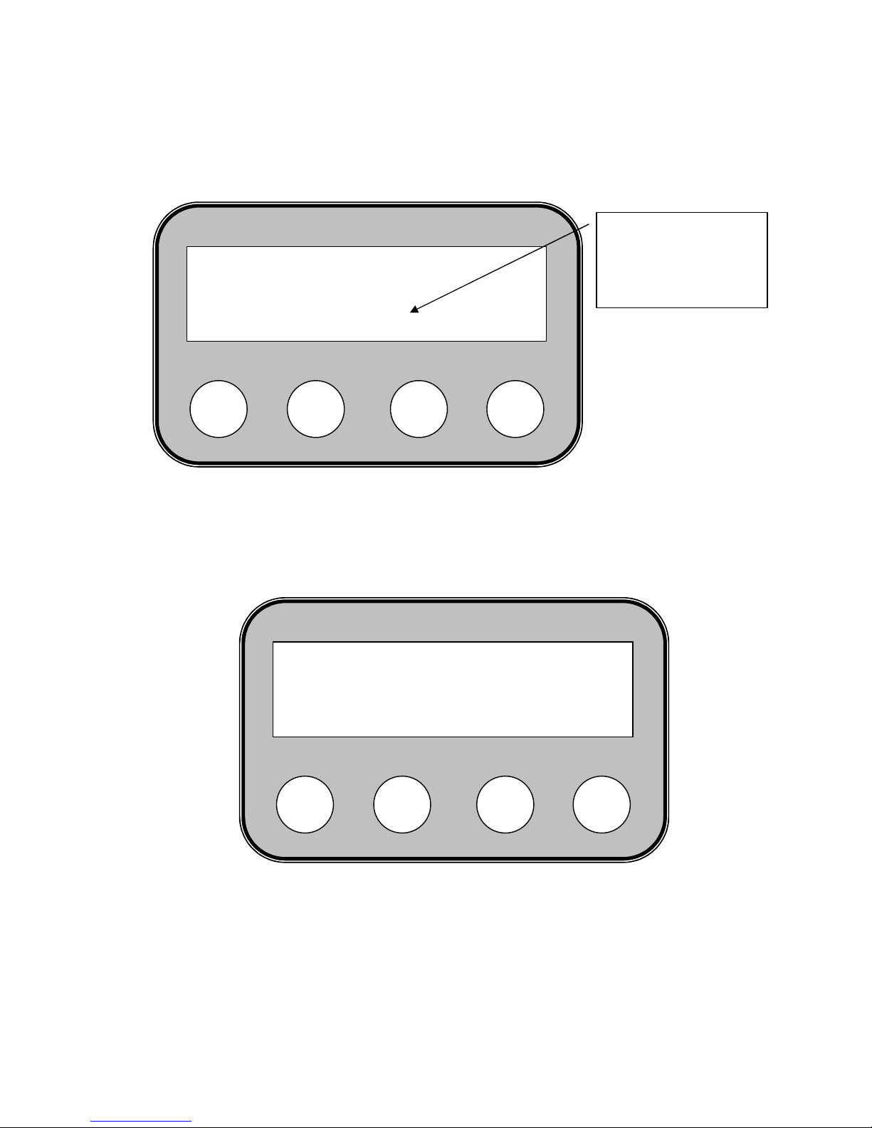
Figure 6.2. Display start screen of automated pellet burner from series “GP IV”.
After the software has been loaded (after a few seconds) a question appears on the display:
(Activate ?):
Figure 6.3. A menu for starting automated pellet burner from series “GP IV”, with invitation
question.
To start the burner operation press the button ”S”, as presented on the above figure.
After the burner operation has been started the display shows a message, presented on the
next figure.
S
_
+
ESC
Activate ?
ENTER
S
_
+
ESC
GREEN ecoTHERM
V2.3 2E
Burner control module
software version
Page 29

Pellet burner GP 45 IV 29
Figure 6.4. The display shows information about the burner’s control module operation mode
– in this case the system checks the fresh (firing) air fan.
„TEST – BLOWING : – shows the operation mode – the fresh air fan performs
preliminary blowing of the burner’s fire-grate (shows the current phase of the
burner ignition).
„ 32о ” - shows (on the left bottom corner of the display, over the button ”S”) the
water temperature in the boiler (degrees Celsius). The temperature value is
indicated if a boiler water temperature sensor is installed and activated from the
controller menu;
„FC: 0% ” – shows the light intensity registered by the photo-sensor, in percent
– displayed in the right bottom corner, over the button “ESC”.
Figure 6.5. The display indicates information about the burner operation mode – in this case
it is ignition fuel doze firing.
S
_
+
ESC
TEST - BLOWING
32o FC: 0%
S
_
+
ESC
IGNITION 1 150
32o FC: 0%
Page 30

Pellet burner GP 45 IV 30
After primary blowing by the fan the burner feeds ignition fuel doze and the process of firing
begins. The display shows “IGNITION 1” – first attempt for ignition, which has to be
completed within a defined period of time, adjusted in the control module software.
The burner’s control module is factory programmed with optimal settings for operation. The
burner can operate within a discreet number of heating output levels. The last, maximum
level of the burner’s heating output is adjusted to achieve higher output than its nominal –
this mode should be chosen when the used fuel is with lower caloricity or when the heat
energy consumption is higher than the burner’s nominal output.
Operation modes at maximum heating output, exceeding the burner’s nominal, are
recommended for short periods of time (total usage up to 10 hours per heating season),
because such modes could lead to increased heat loads over the burner’s construction and
to decrease its life resource.
The practice shows that the factory set parameters do not require additional adjustment,
even if different fuel types are used.
The manufacture company reserves its right to make changes over the appliance
settings values, without obligation to inform the end customers.
The parameter values, which define the heating output of a burner from series “GP”
are determined under the following conditions:
The utilized wood pellets are with diameter 6 mm from category ENplus-A1
(category A, see the wood pellets categorization table);
The tilt angle between the fuel transport auger axis and the horizontal plane is
45o;
The ash content (mineral inflammable mass) does not change significantly the
fuel burning heat value (its caloricity), but requires specialized construction of
the burner’s main module, in order to achieve efficient and economic burning
process. Therefore the fuel compatibility and efficiency have to be checked and
utilized in the appliance after approving results;
The manufacture company reserves its right to change the default values of the
parameters, which control the burner operation, without obligation to inform its
customers;
The heating output level factory settings, providing optimum burner operation,
are presented in Table 6.1;
The presented heating output levels determine the heating output and the
burner operation mode;
The burner initial adjustment has to be performed by trained servicing
technician, as no other adjustments by the end user are required after that;
Next follows a description of how to determine the fuel consumption and
respectively calculation of the burner heating output:
Switch on the burner;
Take off the fuel feeding flexible pipe from the burner module and direct it to a
container (for example plastic bag, utensil or other), where to gather the fuel
dropped by the auger;
An authorized technician has to choose “Advance menu” and activate the
parameter “Stoker adj.”. EXPLANATION: the access to this menu is password
protected;
As a next step leave the auger operating for 6 minutes. The pellets quantity
gathered in the container has to be weigh (measured) and registered in the
controller by using the buttons with indicated directing information. After that the
burner operation has to be activated again. If known and necessary the pellets
Page 31

Pellet burner GP 45 IV 31
caloricity can be entered in the controller. The factory set caloricity value for
wood pellets is 4,8 kWh/kg. After the data input it must be saved by choosing
the relevant button from the menu – the information on the control module
display provides directions for performance of the necessary steps from the
initial adjustment procedure. After performing the initial set up the burner
provides guaranteed heating output.
6.2.7. ADJUSTMENT OF THE BURNER OUTPUT ACCORDING TO THE HEAT
CONSUMPTION.
For optimal, reliable and efficient operation of a burner from series “GP” and a heat
consuming appliance – result from the burning process, it is recommended to adjust the
burner according to the heat consumption which will be covered. This can be achieved by
adjusting its heating output by selecting suitable output level as presented in Table 6.1.
The adjustment of the burner’s heating output does not require additional firing air flow rate
adjustments (fresh air fan), as it is performed automatically by the factory set program in the
burner’s control module.
6.2.8. NOMINAL OPERATION MODE OF THE BURNER.
After completion of the burner starting process (the fuel in the burner combustion chamber
has been fired successfully) and the heat consuming appliance has been heated and
tempered, it can be said that the system operates in nominal mode. All adjustments and
checks over the burner (and the heat consuming appliance) operation have to be performed
in nominal mode. It is necessary to assign the burner heating output to correspond to the
consumed heat energy by the appliance, in nominal operation mode.
In nominal heating output mode the so called “hot test” should be performed over the system,
according to the acting regulations.
The firing air flow rate is highly important about the system (burner – appliance)
operation mode and its efficiency. When the air quantity is less than the
optimal, it leads to incomplete fuel burning. Also when the air consumption is
higher than the optimal, it leads to cooling of the burning zone and again to
incomplete fuel burning. Therefore free air access must be provided (to the
burner as well as to the premise where it is installed), that will be transferred to
the burning zone by the burner’s fan, allowing to achieve optimal parameters and
economic operation of the appliance.
6.2.9. OPERATION MODE OF THE AUTOMATED WOOD PELLET BURNER FROM
SERIES “GP IV”.
After successful fuel firing the burner transits to stabilization of the burning process and the
display shows the following information (Figure 6.6.):
Page 32
Pellet burner GP 45 IV 32
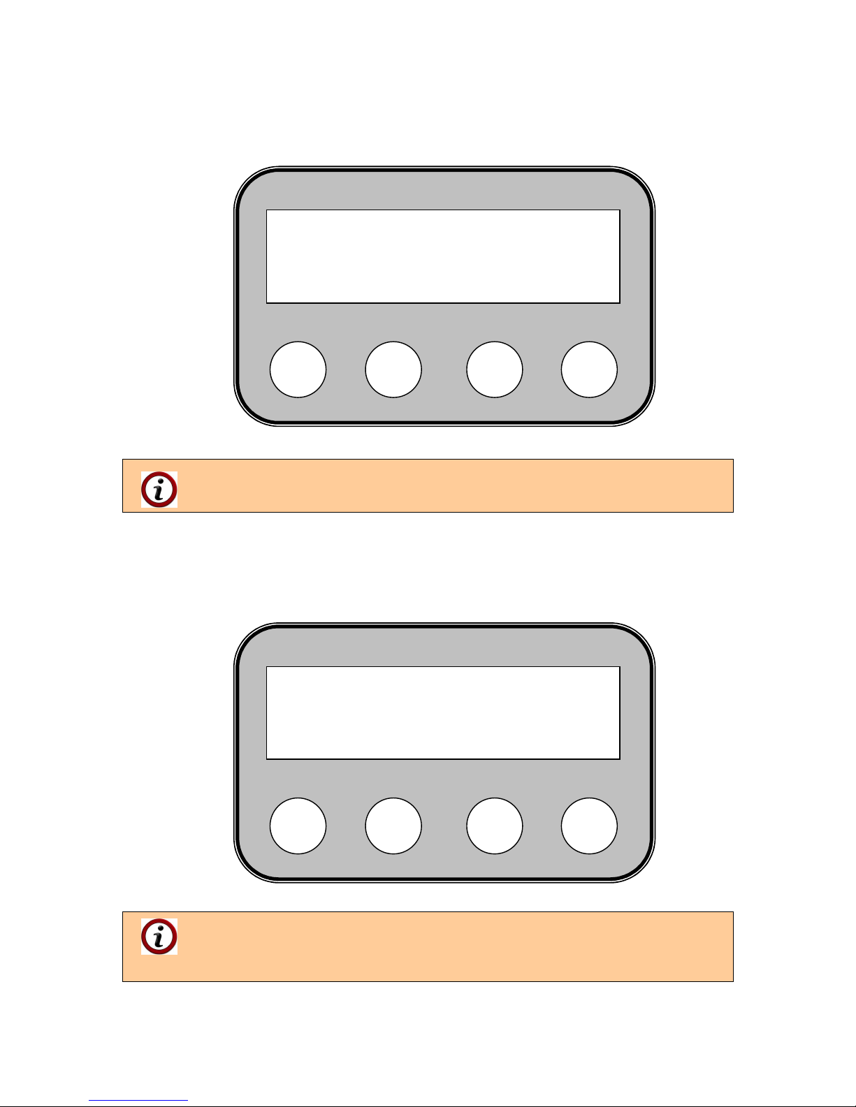
Figure 6.6. The display shows information about the burner operation mode – transition
mode – transition from ignition to burning process stabilization in minimum heating output
operation mode.
„TRANS.:10kW „ – shows that the burner is in transition phase for stabilization of
the burning process, with heating output 10 kW.
After completing the transition mode the burner transits to operation mode as presented on
Figure 6.7.
Figure 6.7. The display shows information about the burner heating output level in maximum
output mode.
„COMBUST 5 – 50kW ” – shows the burner heating output level (in this case
5th level and the burner heating output is 50 kW);
„72о ”- indicates the water temperature, oC;
“FC: 98%” – indicates the light intensity registered by the photo-sensor, %.
S
_
+
ESC
COMBUST 5 50kW
72o FC: 98%
S
_
+
ESC
TRANS. : 10kW
32o FC: 65%
Page 33

Pellet burner GP 45 IV 33
6.2.10. USER MENUES FROM THE BURNER’S CONTROLLER.
The burner menu can be entered by pressing and holding the button “S”. To exit the chosen
submenu press the button “Esc”.
Figure 6.8. Pressing the button “S” provides availability to choose submenu from the burner’s
control module.
6.2.11. USER MENUES FROM THE BURNER’S CONTROLLER.
6.2.12. MENU „EFFECT LEVEL”.
Figure 6.9. Menu “EFFECT LEVEL” – choice of heating output level of a burner from series
“GP IV”.
In this menu the desired operation heating output level of the burner can be chosen.
Table 6.1 presents the heating output values, achieved by the burner operation according to
the selected output level.
S
_
+
ESC
COMBUST 5 50kW
75o FC: 98%
S
_
+
ESC
EFFECT LEVEL
ENTER EXIT
Page 34
Pellet burner GP 45 IV 34
Table 6.1. Heating output of a pellet burner from series “GP 45 IV” according to the heating
output level.
Parameter Dimension Value
Model - GP 45 IV
Heating output level kW -
1 kW 14.0
2 kW 25.0
3 kW 35.0
4 kW 45.0
5 kW 50.0
It is recommended to operate the pellet burner up to 4-th heating output
level inclusive, as 5th level should be used exceptionally only for short periods of
time.
To choose the „EFFECT LEVEL” menu press the button below ENTER – „S”. To switch to
another menu press the button “+” located below the arrow on the display. The button “ESC”
serves to exit the submenu and return to the main menu.
By entering the „EFFECT LEVEL” menu the user is allowed to choose one of the five
heating output levels for burner operation.
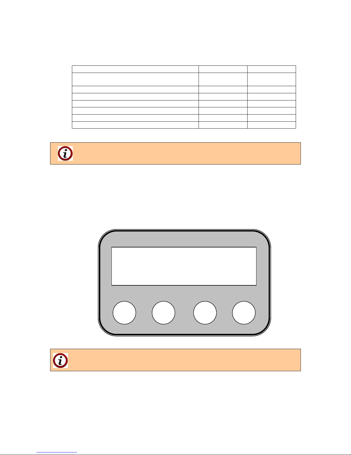
Figure 6.10. Heating output level choice of a burner from series “GP IV”.
The desired heating output level of the burner can be chosen by using the buttons
“+” and “–”. After that press the button “S” in order to confirm your choice. To exit
the menu press the button “ESC”.
S
_
+
ESC
Еffect level [n]
O:5 N:5
Page 35

Pellet burner GP 45 IV 35
6.3. REGULATING THE BURNER’S HEATING OUTPUT.
The burner heating output regulation can be performed by adjusting the level defining its
output. Information about the burner heating output for every level is presented in Table 6.1.
If the used fuel type has been changed (change of the wood pellets category) a
new adjustment of the burner’s heating output level might be required.
6.3.1. DECREASING THE BURNER’S HEATING OUTPUT.
It can be achieved by reducing the burner’s heating output level, which decreases the
assigned heating output and respectively the fuel consumption.
6.3.2. INCREASING THE BURNER’S HEATING OUTPUT.
The burner’s heating output increase can be achieved by increasing its heating output level,
which increases the assigned heating output and respectively the fuel consumption.
If the heating output, respectively the fuel consumption, have been changed, the
control module algorithm automatically changes the fresh air flow rate, supplied
by the fan, which provides optimal operation mode within wide heating output
range.
6.4. STOPPING THE BURNER OPERATION.
Stopping the burner operation can be achieved by its control module, which submits
operation signal. Restore of the burner operation can be achieved by changing the control
module adjustment, which commands the burner operation. In case operation is not needed
for longer period of time, then the burner combustion chamber has to be cleaned from the
ash deposits and also to cut off the appliance power supply to which it is connected.
6.4.1 STOPPING THE BURNER OPERATION BY THE SWTICH “START”.
By the switch “START” (which has to be installed by the servicing technician during the
burner installation, according to the attached wiring diagrams) the burner can be switched on
and respectively switched off. If it is switched off the display shows message “FINAL
COMBUSTION”.
The burner stopping must be performed only by the switch “START”, and not by
cutting off the appliance main power supply. By stopping the burner by the switch
“START” it performs controlled shut down process, during which the appliance
cools down, completes the rest fuel burning and saves the appliance reliability.
6.4.2. STOPPING THE BURNER OPERATION BY THE CONTROL MODULE MENU.
To stop the burner operation it is necessary to complete the following actions:
Press and hold the button “ESC” for more than 5 seconds;
Choose answer “YES” when asked to “Make final combustion?“ on the display;
Page 36

Pellet burner GP 45 IV 36
The choice for stopping the burner operation is shown as indication „Final combustion”
followed by burner stop.
Another method to stop the burner operation is from the control module menu „MAKE FINAL
COMB.”
This option for stopping the burner operation should be used when there is
remaining fuel in the burner’s fire-grate, in order to perform final combustion.
Figure 6.11. Choice of menu “MAKE FINAL COMB.”, which is used for stopping the
operation of a burner from series “GP IV”.
To enter the menu “MAKE FINAL COMB.” press the button “S”. To exit or cancel
the command press the button “ESC”. To switch to other menus press the
buttons “+“ or “–“.
Figure 6.12. The controller display indicates a question for stopping operation of a burner
from series “GP IV”.
S
_
+
ESC
MAKE FINAL COMB.
ENTER EXIT
S
_
+
ESC
Make final comb. ?
[YES] [NO]
Page 37

Pellet burner GP 45 IV 37
To initiate fuel final combustion the button “S” must be pressed, which is located bellow
[YES]. To cancel the final combustion initiation or to return to the previous menu press the
button “ESC”, located bellow [NO].
In case the pellet burner from series “GP” should be stopped from operation, an
entire cleaning of the combustion chamber from the ash deposits has to be
performed, as well as cleaning of the appliance heat exchanging surfaces, to
which it is mounted, because the ash has corrosive influence over the steel
surfaces, which reduces the life of the appliance. A prophylaxis of the burner by
specialized servicing company has to be performed also. Observance of these
procedures provide longer and reliable operation life of the burner.
If an operation stop signal is received by the burner the fuel feeding stops, but its
fresh air fan continues operation. Therefore after receiving a stop signal the
burner continues to burn and to generate heat energy, which makes it inert,
respectively the entire heating system becomes inert. This feature is important if
the radiators are equipped with thermostatic regulators (or other control
components), which close the circulations water flow. As a consequence of this
process the generated by the burner energy might not be “unloaded” and could
lead to overheating of the appliance. Therefore in case a pellet burner from
series “GP” is used and the heating system radiators are equipped with such
thermostatic regulators (heads) it is necessary not to close them completely,
and/or at least one of the radiators should not be equipped with such regulator, in
order to ensure constant energy release in all operation modes.
6.5. SWITCHING OFF THE PELLET BURNER FROM SERIES “GP IV” BY EXTERNAL
MODULE, CONTROLLING ITS OPERATION.
The burner switch off is achieved by interrupting its operation signal, which is submitted to
the burner by external module or by performing the procedure for stopping its operation, as
described in the previous chapter. When the burner transits from burning mode to pause
mode or to “shut down” mode, then the control module performs the so called process of
“controlled stopping”, during which the fresh air fan continues its operation and the
controllers monitors the emergency signals. After the burner cools down its power supply has
to be cut off. It is also recommended to clean the system burner-appliance from the ash
deposits.
6.5.1. BURNER EMERGENCY SHUT DOWN.
During operation of the burner emergency mode situations are possible to occur. Such
situations are read by the control module and it automatically performs prevention
procedures. The burner controller transits to emergency mode by indicating an error code on
the display. The alarm codes and other messages are presented in Table 7.2.
If an emergency situation occurs the failure/alarm code, shown on the display, must be
checked and the relevant corrective measures should be taken, in order to remove the failure
cause. After that the burner should be restarted from its power supply. Before restarting the
burner it is necessary to clean its fire-grate from the ash deposits and fuel remaining;
In case of overheating (emergency situation) of the appliance to which the burner
is mounted, the emergency thermostat activates, which is MANDATORY
equipment and is not part of the burner’s delivery kit. The emergency cause must
be diagnosed and removed. The emergency thermostat must be switched back
on manually, so the burner can receive power supply signal.
Page 38
Pellet burner GP 45 IV 38
In case the burner’s fuel inlet pipe has been overheated (it is also an emergency
situation) a sensor activates, that monitors the temperature in this zone and
prevents from the so called “back fire” to the fuel transport auger. After cooling of
the main module the reason for the emergency must be determined and the
relevant measures should be taken. After removing the reason for excessive
temperature in the pipe (overheating) it could be required to replace the sensor
with new one.
6.6. MENU FOR VIZUALIZATION OF ALARMS/ERRORS LIST, OCCURRED DURING
OPERATION OF PELLET BURNER FROM SERIES „GP IV”.
In order to check the last errors/alarms, occurred during the burner operation, it is necessary
to enter the menu “LOG”.
The log menu shows a list with the last 10 errors, occurred during burner
operation. If a new error occurs, the oldest deletes and the newest one goes on
top of the list.
Figure 6.13. The controller display shows the “LOG” menu with the error number and the
relevant code.
Press the button “ESC” to exit the menu.
The error codes and their explanation are presented in Table 7.2.
6.7. RESTARTING THE PELLET BURNER OPERATION.
Burner restarting is required in situations when the burner operation is assigned but its
control module had switched to protection mode, different from the nominal mode, and the
burner is not operating. The display shows the message code, which has to be determined,
the relevant measures for its removal has to be taken and after then the burner has to be
restarted – it can be performed by switching off and then back on (restarting) the main
module power supply (for example by switching the control panel power switch to which it is
connected). Before restarting the burner it is recommended to check and clean its fire-grate.
S
_
+
ESC
LOG error: 1: 22
EXIT
Page 39
Pellet burner GP 45 IV 39
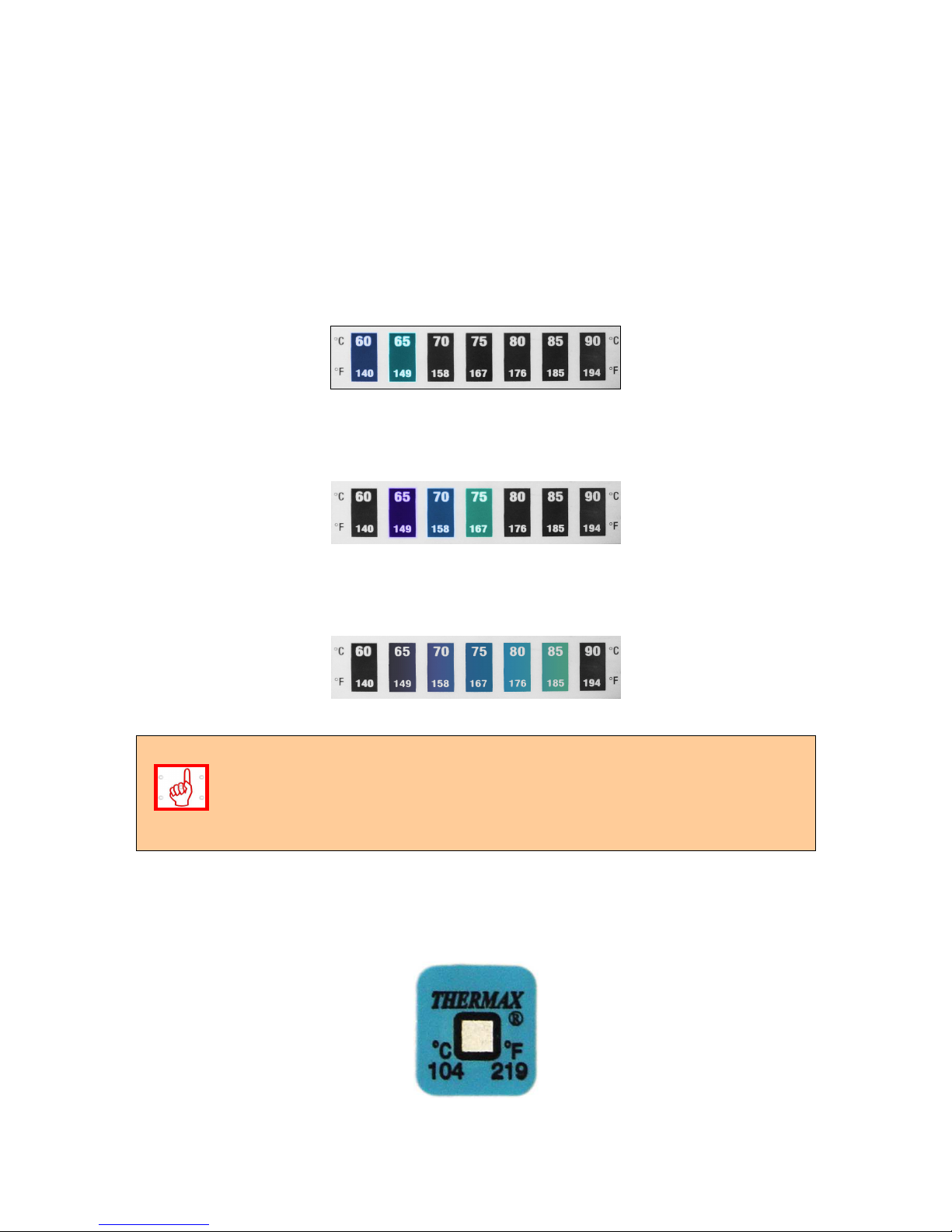
6.8. DESCRIPTION OF THE THERMO-STICKERS FUNCTION FOR MONITORING THE
SYSTEM CONDITION.
The thermo-sticker is used for measurement of the temperature in specific zone of the
burner. By this measurement the system condition can be determined as well as the
necessity for prevention measures and servicing actions over the appliance, to which the
burner is installed and/or of the flue gas line and especially the chimney tract.
Figure 6.14. View of the reversible (self restoring) thermo-sticker that determines the burner
operating temperature in the zone where it is labeled – increased temperature condition
within 60 – 65
o
C.
Figure 6.15. View of the reversible (self restoring) thermo-sticker that determines the burner
operating temperature in the zone where it is labeled – increased temperature condition
within 65 – 75oC.
Figure 6.16. View of the reversible (self restoring) thermo-sticker that determines the burner
operating temperature in the zone where it is labeled – increased temperature condition
within 75 – 85oC.
The reversible thermo-sticker has to be checked at every servicing (visit by the
user for refueling, cleaning, inspection, etc.) of the appliance and the burner. It
shows the current temperature of the burner during operation and provides
information about the ash contamination level and the necessity for cleaning, as
well the chimney draught influence over the entire system – pellet burner –
appliance – chimney.
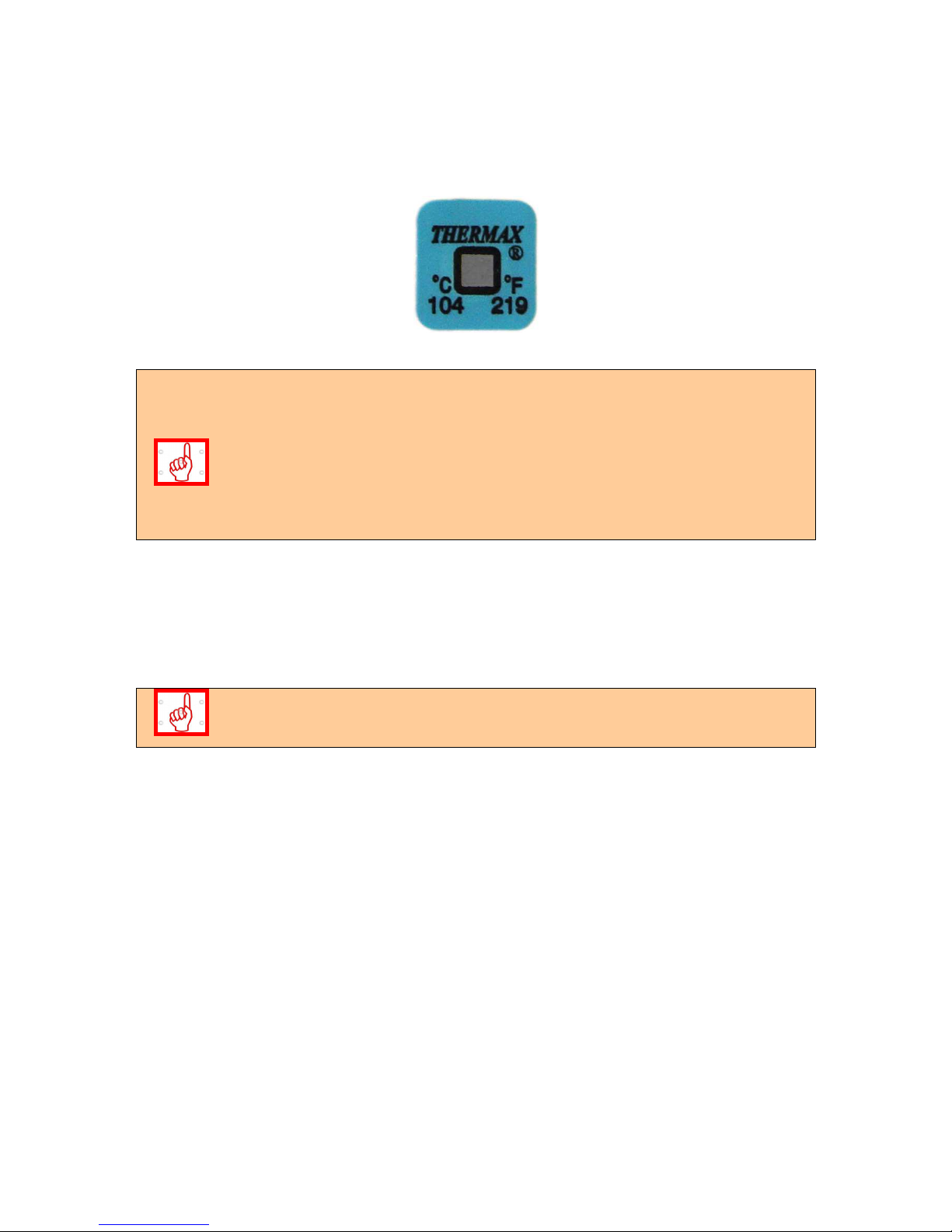
Figure 6.17. View of the irreversible thermo-sticker (not self recovering) – picture of its
normal condition, the burner’s pellet inlet pipe temperature had not been exceeded over the
limit value – 104oC.
Page 40
Pellet burner GP 45 IV 40
Figure 6.18. View of the irreversible thermo-sticker (not self recovering) – emergency
condition, the burner’s pellet inlet pipe temperature had been exceeded over the limit value –
104
o
C.
The irreversible thermo-sticker activation is an indication for overheating of the
burner’s inlet pellets pipe. The sticker condition can not be recovered and it is
necessary to remove the reason for its activation. After that the sticker has to be
replaced with new one – to be performed by servicing technician. The activation
of the sticker occurs when hot flue gasses from the burning zone flow towards
the flexible pipe that connects the auger and the burner’s main module, resulting
from increased resistance in the chimney pipe lines or due to decreased chimney
draught. Such situations are considered as emergency and are not covered by
the burner’s warranty.
6.9. REMOVING AND INSTALLING THE FIRE-GRATE DURING CLEANING AND
MAINTENANCE OF THE BURNER FROM SERIES “GP”.
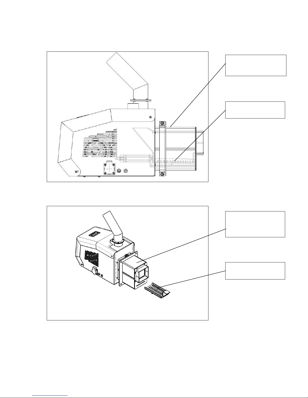
When cleaning the burner’s fire-grate it is necessary to remove it out of the so called
combustion head of the burner’s main module, as presented on Figure 6.19 and Figure 6.20.
The burner’s fire grate has to be removed from the main module after its cooling,
in order to ensure safely operation during its cleaning. To remove the fire-grate it
is recommended to use personal safety equipment and tools (for example pliers).
When cleaning the fire-grate it is required to ensure that its air supplying orifices are well
cleaned, which provides effective burning process and optimal fire-grate cooling.
Page 41
Pellet burner GP 45 IV 41
Figure 6.19. Burner’s main module and fire-grate view.
Figure 6.20. View of the burner’s main module with removed fire-grate.
After complete cleaning of the fire-grate from the ash residues and other particles (for
example slag or unburned fuel) it is necessary to install the fire-grate at its normal position.
The fire-grate correct positioning can be achieved by tilting its opened side and tuck it under
the burner’s main module fire-grate base.
Burner’s main module
combustion head
Burner’s fire-grate
Burner’s main module
combustion head
Burner’s fire-grate
Page 42

Pellet burner GP 45 IV 42
Installation of the fire-grate can be completed in two steps:
The fire-grate has to be positioned so its legs contact the bottom of the burner’s main
module combustion head;
Move the fire-grate so it completely fits the combustion head of the main module.
6.10. INTRODUCING THE USER WITH THE MAINTENANCE AND ADJUSTMENT
PROCEDURES OF PELLET BURNER FROM SERIES “GP”.
It is required that the users are well introduced, in details, to the presented manual for
operation of the burner, as well as to its operation, adjustment of the heating output level and
the maintenance methods.
The combustion chamber cleaning from the ash deposits has to be performed periodically (at
least once per day or at longer periods, depending on the fuel’s ash content, but no longer
than 5 days of operation). The customer must shut down the burner by observing the
instructions described in the above topics. This ensures effective fuel after burning and
cooling of the combustion chamber. After cooling of the burner the ash residues have to be
cleaned by using personal safety equipment and proper tools – working gloves, putty-knife.
Figure 6.21. A pair of working gloves, granted for easier and safer cleaning of the burner’s
main module.
The flexible pellets feeding pipe has to be cleaned also, because during transportation of the
pellets dust deposits could gather in the pipe, which might lead to difficult fuel supplying and
to firing of the dust, in case of emergency situations caused by the penetration of hot flue
gasses through it.
How to restart the burner – after removing the normal operation fault cause the burner
restoring to operation can be achieved by switching off and then on (restarting) its main
power supply.
Page 43

Pellet burner GP 45 IV 43
Regular cleaning of the burner’s components and modules ensure its reliable and
economic operation, and conditions for long life operation.
6.11. SAFETY AND UNPREDICTED RISKS.
Risks related to the “GP” burner usage:
The automated pellet burner from series “GP” is designed and manufactured in compliance
with the major safety European standards and directives. Danger conditions may occur in the
following situations:
The automated pellet burner from series “GP” has been improperly used;
The pellet burner is installed by unqualified personal;
The instructions for safe usage, presented in this manual, are not observed;
Unpredicted risks:
The pellet burner from series „GP” is designed and manufactured in compliance with the
acting safety standards. Although all possible risks, resulting by its improper usage, are
preliminary considered, it is possible that the following situations may occur:
Risks of burning, caused by the high temperature from the burning process in the
combustion chamber, during cleaning the burning zone or unburned material in the
fire-grate;
Risks of electrical shock from indirect contact. The pellet burner from “GP” series
is connected to the electrical network and the control modules are positioned in the
control board, equipped with the necessary safety devices, protecting against
overload and short circuit. The burner ground connection is mandatory and must
be performed by an authorized technician. Opening the burner’s protection cover
by unauthorized person is strictly forbidden;
Risks of finger injuring during works of maintenance and cleaning. It is
recommended to use proper personal safety equipment;
Risk of strangulation in case of insufficient chimney draught, clogging of the
convection line of the boiler, to which the burner from series “GP” is mounted, or
improper sealing of the flue pipeline.
6.12. COMPLETING THE BURNER’S WARRANTY CARD.
The attached WARRANTY CARD has to be completed by filling in all of the
required information in its fields. The stamp and signature fields have to
be also completed in order to ensure the pellet burner from series “GP”
WARRANTY CARD VALIDITY.
Page 44

Pellet burner GP 45 IV 44
6.13. ACTIVITIES AFTER EXPIRY OF THE BURNER LIFE CYCLE PERIOD.
After expiry of the product life cycle, its extermination has to be performed in protective for
the environment way. Its modules must be disassembled and transferred to second raw
material redemption stations, by observing the principles for separate collection of wastes.
Page 45

Pellet burner GP 45 IV 45
7. FAILURES AND TROUBLESHOOTING.
Table 7.1. Description of the failures during operation of pellet burner from series “GP IV”
and the methods for their removal.
No Failure Reason Troubleshooting
Insufficient heating
output
Increase the burner’s heating output level
Low assigned
temperature
It is necessary to check the circulations
water temperature assigned in the burner’s
control module;
1.
In case the burner
is mounted to hot
water boiler and
the room
temperature is low
Low assigned
temperature of the
room thermostat (if
installed)
It is necessary to check the room thermostat
temperature assignment;
Heating output
exceeding the
consumption
Decrease the burner’s heating output level
High assigned
temperature
It is necessary to check the circulations
water temperature assigned in the burner’s
control module;
2.
In case the burner
is mounted to hot
water boiler and
the room
temperature is high
High assigned
temperature of the
room thermostat (if
installed)
It is necessary to check the room thermostat
temperature assignment;
3.
The burner is
switched on but
there is not burning
process
No assignment for
operation
Check the operation assignment by the
burner’s control module;
4.
Hard fuel ignition Low quality pellets It is necessary to change the pellets,
probably their water content is higher than
the required for normal operation of the
appliance;
5.
The fuel ignition is
accompanied by
abnormal noise
Insufficient
chimney draught
It is necessary to inspect the chimney and
the appliance condition, to which the burner
is mounted and to clean them from the ash
deposits. After cleaning it could be required
to adjust the system’s operation parameters
– ask for servicing assistance;
6.
Overheating of the
appliance to which
the burner is
mounted
No heating load or
incorrect
adjustment of the
burner’s or the
appliance heating
output
It is necessary to perform inspection of the
correct working order of the system burnerappliance and its eventual re-adjustment of
the operation parameters – to be performed
by specialist. After cooling of the consuming
appliance and removal of the failure the
emergency thermostat has to be deactivated
(unscrew the protection cover, press the
button and screw the cover back), and after
that start the burner by restarting it;
7. Fuel does not
ignite
No fuel in the
hopper
The fuel hopper that supplies the transport
auger has to be refueled;
Page 46

Pellet burner GP 45 IV 46
Lack of fuel in the
burner combustion
chamber
The process of ignition can be restored by
restarting the burner;
Presence of fuel
over the burner’s
fire-grate, but it is
not fired or it has
burned and there is
no burning process
Clean the fuel deposits in the burner’s firegrate;
If the ignition element has been damaged or
is not active it must be replaced;
Incorrect operation
of the photosensor, monitoring
the burning
process
The photo-sensor for monitoring of the
burning process has to be adjusted or
replaced – has to be performed by servicing
specialist only;
Lack of electrical
power supply
Check if the burner display is operating and
its indication signals. Check the appliance
power supply working order, to which the
burner is mounted and which supplies the
burner with voltage 220 V, 50 Hz – to be
performed by servicing specialist. Check the
burner wiring according to the attached
diagram. Check for loose electrical
connections - to be performed by servicing
specialist;
No start signal to
the burner
Check if the burner receives start signal and
its module’s electrical connections working
order- to be performed by servicing
specialist. Check for loose electrical
connections. Check the operation module’s
working order, which supplies voltage 220 V,
50 Hz - to be performed by servicing
specialist;
There is operation
signal but the
burner is not
operating
Inspect for presence of activated alarm –
check the alarm signals list on the controller
and its indication, presented in the next
table;
8.
The burner does
not start or stops
operation
Blown fuses
To be performed by servicing specialist:
check the fuses condition and if necessary
replace them with the same type fuses
(Warning: the fuses F1, F2, F3 and F4 are
fast reacting);
Low quality fuel It is necessary to replace the fuel, its water
content is probably higher than the normal
required for normal operation of the burner;
9. The flame is dim
and the chimney
smokes
Improper
adjustment of the
appliance
It is necessary to adjust the appliance
operation parameters - to be performed by
servicing specialist;
Page 47

Pellet burner GP 45 IV 47
Incorrectly
positioned photosensor
Change the photo-sensor position by turning
it around its longitudinal axis;
The photo-sensor
surface is dirty
Clean it carefully from the dirt;
10.
The burner starts
but can not transit
to stable operation
mode
The photo-sensor
is damaged –
tracks of burning
over its surface
It is necessary to replace the photo-sensor
with new one - to be performed by servicing
specialist;
Incorrect operation
of the photo-sensor
Check the photo-sensor working order;
Check the burner’s heating output level
adjustment
11.
The burner
operates unstable
The control module
settings has been
changed
Check the control module settings - to be
performed by servicing specialist;
12. Abnormal heating
of the burner’s fuel
inlet pipe
Insufficient
chimney draught or
dirty appliance
It is necessary to clean the appliance,
eventually the chimney. Possible solution is
to install additional flue gas extraction fan
and/or to change the chimney*;
13. Abnormal heating
of the burner’s fuel
inlet pipe and
activation of its
emergency
thermostat
Low chimney
draught or the
appliance is
clogged from ash
particles
It is necessary to clean the appliance,
eventually the chimney. It is necessary to
restart the burner. Possible solution is to
install additional flue gas extraction fan
and/or to change the chimney tract*;
14. Indication for
increased
temperature by the
reversible thermosticker
Increased
resistance in the
flue gas extraction
line or insufficient
chimney draught
It is necessary to clean the appliance and the
chimney from the ash deposits. In case of
insufficient chimney draught install additional
flue gas extraction fan and/or to change the
chimney - to be performed by servicing
specialist;
15. Activation of the
irreversible thermosticker, labeled on
the pellets inlet
pipe
Exceed of the
operation
temperature in this
pipe, which in most
cases is result by
the flow of hot flue
gasses through it
It is necessary to clean the appliance, the
chimney and the burner from the ash
deposits - to be performed by servicing
specialist;
16. Dirty and/or melted
photo-sensor
Incorrect stopping
of the burner
operation
It is necessary to clean the photo-sensor
surface or to replace it with new one. It is
required to observe the stopping procedure
presented in this manual;
17. Presence of
unburned fuel in
the ash-tray
Ineffective fuel
combustion
It is necessary to adjust the operation
parameters of the appliance – adjustment
and/or consultation with servicing specialist
is required;
18.
Slag deposits in
the combustion
chamber (melted
mineral mass)
The used fuel is
with high ash
content and does
not comply with the
appliance
requirements
Replace the fuel with such that complies with
the requirements for reliable operation of the
burner;
Page 48

Pellet burner GP 45 IV 48
Burner operation
with heating output
over the nominal
Change the burner’s heating output by
changing its heating output level;
19. Alarm code, shown
on the burner’s
controller display
Problem in the
burner operation
Check the code meaning in the next table.
Ask for assistance from servicing technician;
20. The burner has
stopped, but it
operates after
restarting
The photo-sensor
submits wrong
information to the
control module
Check the fuel quantity over the fire-grate.
Ask for assistance from servicing specialist;
21. High flue gas
temperature (if a
thermometer is
installed)
Dirty heat
exchanging
surfaces
depending on the
appliance type and
the operation mode
It is necessary to clean the appliance heat
exchanging surfaces;
22. Presence of smoke
in the boiler room
after period of
operation
Dirty or clogged
tract for extraction
of the flue gasses
out of the
appliance – heat
exchanger
Cleaning of the appliance – heat exchanger,
from the ash residues;
23. The burner stops
when it reaches
the assigned
temperature or
when it performs
periodical
intermediate stops
for blowing, but
shows message:
“Eror - final
combustion failed”
Pellets with high
ash content, fuel
deposits in the pipe
It is necessary to reduce the burner’s heating
output and to replace with fuel corresponding
to the requirements for reliable operation of
the burner;
24. Other, not
presented failures
Ask for servicing assistance;
EXPLANATION:
*: excessive heating of the pellets inlet pipe, in most cases resulting from contamination of
the appliance’s heat exchanging surfaces, to which the pellet burner is mounted;
** In case of insufficient chimney draught it is recommended to ask for servicing assistance –
cleaning, chimney inspection or others.
Page 49

Pellet burner GP 45 IV 49
Table 7.2. Description of the faults included in the controller menu „LOG” list from a “GP IV”
series pellet burner.
No Alarm code
Description of the alarm Troubleshooting
1.
10 Failed fuel ignition Clean the burner’s fire-grate;
Check for fuel in the hopper;
Ask for servicing assistance;
2.
11 Flame dyes during burner
operation
Ask for servicing assistance;
3.
12 Photo sensor fault Ask for servicing assistance;
4.
13 PC motherboard temperature
is too high
Switch off the burner until ;
Ask for servicing assistance;
5.
14 The temperature sensor
measured value is under 5oC
The circulations water is with dangerously
low temperature and its freezing is
possible; Ask for servicing assistance and
installation inspection;
6.
15 The temperature sensor
measured value is over 120oC
The circulations water is with dangerously
high temperature. Overheating of the
appliance and the heating system is
possible;
Ask for servicing assistance and
inspection of the installation;
7.
16 PC motherboard failure Ask for servicing assistance;
8.
18 Fan relay fault Ask for servicing assistance;
9.
19 The fan is not rotating Ask for servicing assistance;
10.
20 The fan rotates with improper
speed
Ask for servicing assistance;
11.
21 Primary ignition is not
completed
Check fuel quantity and the auger
operation;
Ask for servicing assistance;
12.
22 Fuel transport auger fault Ask for servicing assistance;
13.
23 The photo sensor does not
dim during final combustion
Ask for servicing assistance;
14.
24 Loss of light by the photo-
sensor during operation and
after ignition phase
Ask for servicing assistance;
Page 50

Pellet burner GP 45 IV 50
Table 7.3. Description of faults/errors, shown on the control module display of a burner from
series “GP IV”.
No
Message shown on
the display
Meaning
Troubleshooting
1. IGNITION FAILED - Check for fuel and auger operation
or ask for servicing assistance;
2. LOST FIRE IN
COMBUSTION
Looses fire during
operation
Check the auger connection, restart the
burner;
3. STOKER FAULT Auger connection is
interrupted
Check the auger power supply, possible
reason could be overheating of the
pellets inlet pipe – check the thermostickers;
4. TEMP- SENSOR LOW Temperature sensor
is switched off1
Check NTC sensor connection
5. PHOTOSENS Photo sensor fault Check the photo sensor condition,
replace it if necessary – to be performed
by servicing assistance;
6. TEMP SENSOR
OVERHEAT
High temperature
read by the
temperature sensor
Check the hot water boiler condition, cool
down the appliance;
Page 51

Pellet burner GP 45 IV 51
8. WIRING DIAGRAM OF AUTOMATED WOOD PELLET BURNER FROM SERIES “GP
IV”.
The wiring diagram of automated pellet burner from series “GP 45 IV” is presented on Figure
8.1.
Page 52

Pellet burner GP 45 IV 52
K1 K2 K3 K4 K5 K6 K7 K8 K9 K10 K11 K12 K13
K14 K15 K16 K17 K18
K19 K20 K21 K22 K23
EXT3
EXT6
EXT2
EXT4
EXT5
PE
Zero
Phase
No use
Yellow
-
green
Phase
Emergency
thermostat
Hot water
boiler
N N N N
Air fan
Auger
Extraction fan - option
F1/6,3A
Ignition
F2 /800mA –F
Fresh air fan
F3 /1A –F
Auger
F4/1A –F
Flue gas
extraction
fan -option
Hall
sensor -
NTC sensor
Circulations water
t
0
Photo sensor
Room
thermostat
- option
TD – safety thermo-disc (on
pellets inlet pipe – 950 C)
WARNING – remove the bridge in case of room
thermostat and switch “START” installation
N
Filter
C = 100nF/500VAC
R = 220 Ohms
230V, 50Hz
Ignition
M1
TD
M2 M3
EXT1
START
Figure 8.1. Schematic wiring and connection diagram of automated pellet burner from series “GP 45 IV”.
Page 53

Pellet burner GP 45 IV 53
WARRANTY CONDITIONS
The manufacturing company guarantees correct and trouble free operation of the
pellet burner from series “GP” only if the installation and operation requirements
during initialization and maintenance are observed.
The warranty period of the automated pellet burner start is considered from the date of
completing and stamping its warranty card.
The pellet burner warranty starts from the day of initialization to operation, but no longer than
6 months from the date of purchase.
The warranty period of the product is 24 (twenty four) months.
The warranty is valid only when the purchase invoice and original warranty card are
presented.
THE PRODUCT WARRANTY IS NOT VALID in the following situations:
Damages over the pellet burner caused by improper storage, transport and/or
unloading, which are not organized by the manufacturing company;
Failures caused by natural disasters (earthquakes, fire, floods and others);
The requirements for installation, operation and periodical maintenance, presented in
the current manual book, are not observed;
Attempts for removing any defect, performed by the buyer or other unauthorized
persons;
Changes over the pellet burner construction;
Incorrect heating calculations and project design for mounting and installation of the
generator;
Failures for which the manufacturing company is not responsible/ which are not under
control;
Malfunctions and damages which are not caused by the pellet burner itself, but have
led to failure in its construction;
In case the irreversible thermo-sticker has been activated or in case it has been
damaged or removed.
Every warranty repair must be written in the product warranty card.
The warranty period is interrupted for the period of time from the date of registering the
warranty claim up to removal of the failure.
 Loading...